EP0549854A1 - Cathode for coating a substrate - Google Patents
Cathode for coating a substrate Download PDFInfo
- Publication number
- EP0549854A1 EP0549854A1 EP92111759A EP92111759A EP0549854A1 EP 0549854 A1 EP0549854 A1 EP 0549854A1 EP 92111759 A EP92111759 A EP 92111759A EP 92111759 A EP92111759 A EP 92111759A EP 0549854 A1 EP0549854 A1 EP 0549854A1
- Authority
- EP
- European Patent Office
- Prior art keywords
- housing
- target
- coating chamber
- cathode
- cylindrical
- Prior art date
- Legal status (The legal status is an assumption and is not a legal conclusion. Google has not performed a legal analysis and makes no representation as to the accuracy of the status listed.)
- Granted
Links
Images
Classifications
-
- H—ELECTRICITY
- H01—ELECTRIC ELEMENTS
- H01J—ELECTRIC DISCHARGE TUBES OR DISCHARGE LAMPS
- H01J37/00—Discharge tubes with provision for introducing objects or material to be exposed to the discharge, e.g. for the purpose of examination or processing thereof
- H01J37/32—Gas-filled discharge tubes
- H01J37/34—Gas-filled discharge tubes operating with cathodic sputtering
- H01J37/3488—Constructional details of particle beam apparatus not otherwise provided for, e.g. arrangement, mounting, housing, environment; special provisions for cleaning or maintenance of the apparatus
- H01J37/3497—Temperature of target
-
- C—CHEMISTRY; METALLURGY
- C23—COATING METALLIC MATERIAL; COATING MATERIAL WITH METALLIC MATERIAL; CHEMICAL SURFACE TREATMENT; DIFFUSION TREATMENT OF METALLIC MATERIAL; COATING BY VACUUM EVAPORATION, BY SPUTTERING, BY ION IMPLANTATION OR BY CHEMICAL VAPOUR DEPOSITION, IN GENERAL; INHIBITING CORROSION OF METALLIC MATERIAL OR INCRUSTATION IN GENERAL
- C23C—COATING METALLIC MATERIAL; COATING MATERIAL WITH METALLIC MATERIAL; SURFACE TREATMENT OF METALLIC MATERIAL BY DIFFUSION INTO THE SURFACE, BY CHEMICAL CONVERSION OR SUBSTITUTION; COATING BY VACUUM EVAPORATION, BY SPUTTERING, BY ION IMPLANTATION OR BY CHEMICAL VAPOUR DEPOSITION, IN GENERAL
- C23C14/00—Coating by vacuum evaporation, by sputtering or by ion implantation of the coating forming material
- C23C14/22—Coating by vacuum evaporation, by sputtering or by ion implantation of the coating forming material characterised by the process of coating
- C23C14/34—Sputtering
- C23C14/3407—Cathode assembly for sputtering apparatus, e.g. Target
-
- H—ELECTRICITY
- H01—ELECTRIC ELEMENTS
- H01J—ELECTRIC DISCHARGE TUBES OR DISCHARGE LAMPS
- H01J37/00—Discharge tubes with provision for introducing objects or material to be exposed to the discharge, e.g. for the purpose of examination or processing thereof
- H01J37/32—Gas-filled discharge tubes
- H01J37/34—Gas-filled discharge tubes operating with cathodic sputtering
- H01J37/3402—Gas-filled discharge tubes operating with cathodic sputtering using supplementary magnetic fields
- H01J37/3405—Magnetron sputtering
- H01J37/3408—Planar magnetron sputtering
-
- H—ELECTRICITY
- H01—ELECTRIC ELEMENTS
- H01J—ELECTRIC DISCHARGE TUBES OR DISCHARGE LAMPS
- H01J37/00—Discharge tubes with provision for introducing objects or material to be exposed to the discharge, e.g. for the purpose of examination or processing thereof
- H01J37/32—Gas-filled discharge tubes
- H01J37/34—Gas-filled discharge tubes operating with cathodic sputtering
- H01J37/3411—Constructional aspects of the reactor
- H01J37/345—Magnet arrangements in particular for cathodic sputtering apparatus
- H01J37/3455—Movable magnets
-
- H—ELECTRICITY
- H01—ELECTRIC ELEMENTS
- H01J—ELECTRIC DISCHARGE TUBES OR DISCHARGE LAMPS
- H01J37/00—Discharge tubes with provision for introducing objects or material to be exposed to the discharge, e.g. for the purpose of examination or processing thereof
- H01J37/32—Gas-filled discharge tubes
- H01J37/34—Gas-filled discharge tubes operating with cathodic sputtering
- H01J37/3411—Constructional aspects of the reactor
- H01J37/345—Magnet arrangements in particular for cathodic sputtering apparatus
- H01J37/3458—Electromagnets in particular for cathodic sputtering apparatus
Definitions
- the invention relates to a cathode for coating a substrate, which is connected to a direct current and / or alternating current source (high frequency source) and is arranged in an evacuable coating chamber which is electrically connected to a target which is atomized and whose atomized particles are deposited on the Precipitate substrate, a process gas can be introduced into the coating chamber and the cathode is formed from a substantially pot-shaped housing, the closed bottom part of which is firmly connected with its outer surface to the target, preferably screwed, and whose open end facing away from the target is in an opening in the outer wall of the coating chamber is sealed so that the interior of the housing is always exposed to atmospheric pressure, while the target and the outer surface of the connected to the Coating chamber protruding, sleeve-shaped part of the housing are acted upon by the pressure prevailing in the coating chamber (addition to P 41 37 483.5).
- the present invention has for its object to provide a sputtering cathode which can be arranged in or on the coating chamber so that its magnet arrangement is also accessible, that is, for example, interchangeable when the coating chamber is evacuated, the space required in comparison to conventional Cathode is particularly small and can also be operated for an ultra-high vacuum process at temperatures of about 200 to 400 ° C.
- an insert which at least partially fills the interior of the housing and which can be locked with the inner wall of the housing in such a way that it forms an approximately circular-cylindrical space with the base part, into which a magnet set with a yoke including an electromagnet can be inserted.
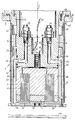
- the invention allows a wide variety of design options; one of them is shown schematically in more detail in the attached drawing, which shows the longitudinal section through the sputter cathode with screwed-on target and through a plane which has the cooling channels and the coolant connections.
- the cathode arranged opposite the substrate 46 essentially consists of a pot-shaped housing 3 formed from several parts, two permanent magnets 4, 5 held in the bottom of the pot-shaped housing 3, one of which has an annular cylindrical configuration and the other a circular cylindrical configuration, with one about circular cylindrical magnetic yoke 6, with the inserted in this circular cylindrical coil or electromagnet 61, a cup-shaped insert 8, which contains the connecting pieces 9, 10 for the cooling channels 11, 12 and the bore 56 for the connecting cable 60 for the electromagnet 61 and the can be locked on the housing 3 with the aid of not shown radially adjustable bolts.
- the pot-shaped housing 3 consists of a flange 23 for holding the cathode on the wall 30 of the process chamber, the two profile rings 24, 25, the ceramic ring 26 arranged between the two profile rings 24, 25, the water-cooled outer sleeve part 27, the soldered base plate 58, the target 29 and the soldered-in threaded sleeve 59.
- the bores 31, 31 ',... Penetrate the cylindrical body and connect the cooling circuit between the forward and the return in the cavity 32.
- These bores or cavities 31, 31 ', ... or 32 correspond to connection bores 33 or 34 which are provided in the insert 8 and which in turn are connected to the cooling channels 11, 12 which in turn are connected via the screw connections or connecting pieces 9 , 10 are connected to the coolant line 35, 36.
- the bore or opening 56 enables the installation of an electromagnet 61 with the associated magnetic yoke 6.
- the cathode described above has the advantage that the cooling jacket or the cavities 31, 31 ',... Or 32 through which the coolant flows are on the outside, while the coolant connections 9, 10 are on the inside, so that there is no leakage in the coolant supply line can lead to a coolant break-in in the process chamber 2.
- the coolant connections can also be easily removed from the screw connections or the connecting pieces 9, 10 without the process chamber 2 having to be ventilated.
- the magnet insert can be replaced when the process chamber 2 is evacuated, and the distance between the magnets 4, 5 and the target 29 can be changed without the process chamber 2 having to be opened or flooded.
- the insert 8 and the magnet set 4, 5, 6, 61 attached to it can also be removed from the cathode simply to the rear or to the top.
- the power supply 52 to the sleeve part 27 or to the target 29 takes place via the locking bolts mentioned above, which are held under prestress and pressed radially outwards (not shown in more detail), so that a secure current transfer between the locking bolts and the Sleeve 27 is guaranteed.
- the HF-resistant insert 8 is finally sealed with the aid of round cord rings (sealing rings) 50, 51 against the inner wall of the housing 3 in such a way that the coolant only from the connection bores 33, 34 into the cavity or intermediate space 32 or the bores 31 , 31 'can occur.
- the base plate 58 is vacuum-soldered to the cylindrical part 27 at all contact points.
- a threaded sleeve 59 is soldered to the base plate 58 for the purpose of central target attachment.
- the housing 3 of the cathode is enclosed by a tubular dark room shield 47 which is fastened to the flange 23 by means of a bayonet connection 57, and that the parts 23 and 24 or the parts 25 and 27 by welding and the parts 24 and 26 or 26 and 25 are connected to one another by brazing and that the flange 23 of the housing 3 is screwed to the collar of the insert 8 which extends radially outwards.
Abstract
Description
Die Erfindung betrifft eine Kathode zum Beschichten eines Substrats, die an eine Gleichstrom- und/oder Wechselstromquelle (Hochfrequenzquelle) angeschlossen und in einer evakuierbaren Beschichtungskammer angeordnet ist, die elektrisch mit einem Target in Verbindung steht, das zerstäubt wird und dessen zerstäubte Teilchen sich auf dem Substrat niederschlagen, wobei in die Beschichtungskammer ein Prozeßgas einbringbar ist und die Kathode aus einem im wesentlichen topfförmigen Gehäuse gebildet ist, dessen geschlossenes Bodenteil mit seiner Außenfläche mit dem Target fest verbunden, vorzugsweise verschraubt ist und dessen dem Target abgewandtes, offenes Ende in einer Öffnung in der Außenwand der Beschichtungskammer abgedichtet so gehalten ist, daß der Innenraum des Gehäuses stets dem Atmosphärendruck ausgesetzt ist, während das Target und die Außenfläche des mit diesem verbundenen, in die Beschichtungskammer hineinragenden, hülsenförmigen Teils des Gehäuses von in der Beschichtungskammer jeweils herrschenden Druck beaufschlagt sind (Zusatz zu P 41 37 483.5).The invention relates to a cathode for coating a substrate, which is connected to a direct current and / or alternating current source (high frequency source) and is arranged in an evacuable coating chamber which is electrically connected to a target which is atomized and whose atomized particles are deposited on the Precipitate substrate, a process gas can be introduced into the coating chamber and the cathode is formed from a substantially pot-shaped housing, the closed bottom part of which is firmly connected with its outer surface to the target, preferably screwed, and whose open end facing away from the target is in an opening in the outer wall of the coating chamber is sealed so that the interior of the housing is always exposed to atmospheric pressure, while the target and the outer surface of the connected to the Coating chamber protruding, sleeve-shaped part of the housing are acted upon by the pressure prevailing in the coating chamber (addition to P 41 37 483.5).
Der vorliegenden Erfindung liegt die Aufgabe zugrunde, eine Sputterkathode zu schaffen, die so in bzw. an der Beschichtungskammer angeordnet werden kann, daß ihre Magnetanordnung auch dann zugänglich ist, also beispielsweise austauschbar ist, wenn die Beschichtungskammer evakuiert ist, deren Platzbedarf im Vergleich zu herkömmlichen Kathoden besonders gering ist und die auch für einen Ultra-Hochvakuumprozeß bei Temperaturen von etwa 200 bis 400° C betrieben werden kann.The present invention has for its object to provide a sputtering cathode which can be arranged in or on the coating chamber so that its magnet arrangement is also accessible, that is, for example, interchangeable when the coating chamber is evacuated, the space required in comparison to conventional Cathode is particularly small and can also be operated for an ultra-high vacuum process at temperatures of about 200 to 400 ° C.
Diese Aufgabe wird erfindungsgemäß durch einen den Innenraum des Gehäuses zumindest teilweise ausfüllenden Einsatz gelöst, der mit der Gehäuseinnenwand so verriegelbar ist, daß er mit dem Bodenteil einen etwa kreiszylindrischen Raum bildet, in den ein einen Elektromagneten einschließender Magnetsatz mit Joch einsetzbar ist.This object is achieved according to the invention by an insert which at least partially fills the interior of the housing and which can be locked with the inner wall of the housing in such a way that it forms an approximately circular-cylindrical space with the base part, into which a magnet set with a yoke including an electromagnet can be inserted.
Weitere Merkmale und Einzelheiten sind in den Patentansprüchen näher beschrieben und gekennzeichnet.Further features and details are described and characterized in more detail in the patent claims.
Die Erfindung läßt die verschiedensten Ausführungsmöglichkeiten zu; eine davon ist in der anhängenden Zeichnung schematisch näher dargestellt, die den Längsschnitt durch die Sputterkathode mit angeschraubtem Target und durch eine Ebene, die die Kühlkanäle und die Kühlmittelanschlüsse aufweist, zeigt.The invention allows a wide variety of design options; one of them is shown schematically in more detail in the attached drawing, which shows the longitudinal section through the sputter cathode with screwed-on target and through a plane which has the cooling channels and the coolant connections.
Die dem Substrat 46 gegenüberliegend angeordnete Kathode besteht im wesentlichen aus einem topfförmigen, aus mehreren Teilen gebildeten Gehäuse 3, zwei im Boden des topfförmigen Gehäuses 3 gehaltenen Permanentmagneten 4, 5, von denen der eine eine kreisringzylindrische und der andere eine kreizylindrische Konfiguration aufweist, mit einem etwa kreiszylindrischen Magnetjoch 6, mit der in dieses eingesetzten kreisringzylindrisch ausgeformten Spule bzw. Elektromagneten 61, einem topfförmigen Einsatz 8, der die Anschlußstutzen 9, 10 für die Kühlkanäle 11, 12 und die Bohrung 56 für das Anschlußkabel 60 für den Elektromagneten 61 enthält und der mit Hilfe nicht näher dargestellter, radial verstellbarer Bolzen am Gehäuse 3 verriegelbar ist.The cathode arranged opposite the
Das topfförmige Gehäuse 3 besteht aus einem Flansch 23 zur Halterung der Kathode an der Wand 30 der Prozeßkammer, den beiden Profilringen 24, 25, den zwischen den beiden Profilringen 24, 25 angeordneten Keramikring 26, dem wassergekühlten äußeren Hülsenteil 27, der aufgelöteten Bodenplatte 58, dem Target 29 und der eingelöteten Gewindehülse 59.The pot-
Wie aus Figur 1 ersichtlich, durchdringen die Bohrungen 31, 31', ... den zylindrischen Körper und verbinden im Hohlraum 32 den Kühlkreislauf zwischen Vor- und Rücklauf. Diese Bohrungen bzw. Hohlräume 31, 31', ... bzw. 32 korrespondieren mit Anschlußbohrungen 33 bzw. 34, die im Einsatz 8 vorgesehen sind und die wiederum mit den Kühlkanälen 11, 12 verbunden sind, die ihrerseits über die Verschraubungen oder Stutzen 9, 10 an die Kühlmittelleitung 35, 36 angeschlossen sind. Die Bohrung bzw. Öffnung 56 ermöglicht den Einbau eines Elektromagneten 61 mit dem zugehörigen Magnetjoch 6.As can be seen from FIG. 1, the
Die vorstehend beschriebene Kathode hat den Vorteil, daß sich der Kühlmantel bzw. die vom Kühlmittel durchflossenen Hohlräume 31, 31', ... bzw. 32 außen befinden, während die Kühlmittelanschlüsse 9, 10 innen sind, so daß eine Leckage in der Kühlmittelzuleitung nicht zu einem Kühlmitteleinbruch in die Prozeßkammer 2 führen kann. Die Kühlmittelanschlüsse können auch ohne weiteres von den Verschraubungen bzw. den Anschlußstutzen 9, 10 gelöst werden, ohne daß die Prozeßkammer 2 belüftet werden muß.The cathode described above has the advantage that the cooling jacket or the
Darüber hinaus kann der Magneteinsatz bei evakuierter Prozeßkammer 2 ausgetauscht werden, und es kann der Abstand zwischen den Magneten 4, 5 und dem Target 29 verändert werden, ohne daß die Prozeßkammer 2 geöffnet bzw. geflutet werden muß. Zum Aufheizen der Kathode läßt sich auch der Einsatz 8 und der an diesem befestigte Magnetsatz 4, 5, 6, 61 einfach nach hinten bzw. oben zu aus der Kathode entfernen.In addition, the magnet insert can be replaced when the
Es sei noch erwähnt, daß die Stromzuführung 52 zum Hülsenteil 27 bzw. zum Target 29 über die oben erwähnten Verriegelungsbolzen erfolgt, die unter Vorspannung gehalten und radial nach außen gedrückt werden (nicht näher dargestellt), so daß ein sicherer Stromübergang zwischen den Verriegelungsbolzen und der Hülse 27 gewährleistet ist.It should also be mentioned that the
Der HF-beständige Einsatz 8 ist schließlich mit Hilfe von Rundschnurringen (Dichtringen) 50, 51 so gegenüber der Innenwand des Gehäuses 3 abgedichtet, daß das Kühlmittel nur von den Anschlußbohrungen 33, 34 aus in den Hohlraum bzw. Zwischenraum 32 bzw. die Bohrungen 31, 31' eintreten kann.The HF-
Die Bodenplatte 58 ist mit dem zylindrischen Teil 27 an allen Kontaktstellen vakuumgelötet. Zu der Bodenplatte 58 ist eine Gewindehülse 59 zwecks mittiger Targetbefestigung eingelötet.The
Schließlich sei noch erwähnt, daß das Gehäuse 3 der Kathode von einer rohrförmigen Dunkelraumabschirmung 47 umschlossen ist, die mit Hilfe einer Renkverbindung 57 am Flansch 23 befestigt ist, und daß die Teile 23 und 24 bzw. die Teile 25 und 27 durch Schweißen und die Teile 24 und 26 bzw. 26 und 25 durch Hartlöten miteinander verbunden sind und daß der Flansch 23 des Gehäuses 3 mit dem sich radial nach außen zu erstreckenden Kragen des Einsatzes 8 verschraubt ist.Finally, it should be mentioned that the
- 22nd
- BeschichtungskammerCoating chamber
- 33rd
- Gehäusecasing
- 44th
- PermanentmagnetPermanent magnet
- 55
- PermanentmagnetPermanent magnet
- 66
- MagnetjochMagnetic yoke
- 88th
- Einsatzcommitment
- 99
- AnschlußstutzenConnecting piece
- 1010th
- AnschlußstutzenConnecting piece
- 1111
- KühlkanalCooling channel
- 1212
- KühlkanalCooling channel
- 2323
- Flanschflange
- 2424th
- ProfilringProfile ring
- 2525th
- ProfilringProfile ring
- 2626
- ringförmiges Zwischenstück, Isolierringring-shaped intermediate piece, insulating ring
- 2727
- Hülsenteil (außen)Sleeve part (outside)
- 2929
- TargetTarget
- 3030th
- Wand der ProzeßkammerWall of the process chamber
- 31, 31', ...31, 31 ', ...
- Bohrungdrilling
- 3232
- Hohlraumcavity
- 3333
- AnschlußbohrungConnection hole
- 3434
- AnschlußbohrungConnection hole
- 3535
- KühlmittelleitungCoolant line
- 3636
- KühlmittelleitungCoolant line
- 4646
- SubstratSubstrate
- 4747
- DunkelraumabschirmungDarkroom shielding
- 4848
- Öffnungopening
- 4949
- Innenraum des GehäusesInterior of the housing
- 5050
- RingdichtungRing seal
- 5151
- RingdichtungRing seal
- 5252
- elektrischer Leiterelectrical conductor
- 5353
- elektrischer Leiterelectrical conductor
- 5656
- GewindebohrungTapped hole
- 5757
- RenkverbindungBayonet connection
- 5858
- BodenplatteBase plate
- 5959
- GewindehülseThreaded sleeve
- 6060
- AnschlußkabelConnecting cable
- 6161
- Elektromagnet, SpuleElectromagnet, coil
- 6262
- GehäuseaußenflächeOuter surface of the housing
Claims (2)
Applications Claiming Priority (2)
| Application Number | Priority Date | Filing Date | Title |
|---|---|---|---|
| DE19914143135 DE4143135A1 (en) | 1991-11-14 | 1991-12-28 | Cathode for vapour deposition coating of a substrate |
| DE4143135 | 1991-12-28 |
Publications (2)
| Publication Number | Publication Date |
|---|---|
| EP0549854A1 true EP0549854A1 (en) | 1993-07-07 |
| EP0549854B1 EP0549854B1 (en) | 1996-03-20 |
Family
ID=6448213
Family Applications (1)
| Application Number | Title | Priority Date | Filing Date |
|---|---|---|---|
| EP92111759A Expired - Lifetime EP0549854B1 (en) | 1991-12-28 | 1992-07-10 | Cathode for coating a substrate |
Country Status (3)
| Country | Link |
|---|---|
| EP (1) | EP0549854B1 (en) |
| DE (1) | DE59205763D1 (en) |
| ES (1) | ES2084886T3 (en) |
Cited By (4)
| Publication number | Priority date | Publication date | Assignee | Title |
|---|---|---|---|---|
| WO1995006954A1 (en) * | 1993-08-30 | 1995-03-09 | W. Blösch AG | Magnetic field cathode |
| DE19525007A1 (en) * | 1995-03-09 | 1997-01-09 | Leybold Ag | Cathode arrangement for a device for atomizing a target |
| US5683560A (en) * | 1995-07-08 | 1997-11-04 | Balzers Und Leybold Deutschland Holding Ag | Cathode assembly |
| US6264804B1 (en) | 2000-04-12 | 2001-07-24 | Ske Technology Corp. | System and method for handling and masking a substrate in a sputter deposition system |
Families Citing this family (4)
| Publication number | Priority date | Publication date | Assignee | Title |
|---|---|---|---|---|
| JPH11339254A (en) | 1998-03-24 | 1999-12-10 | Quantum Corp | Magnetic recording tape, information storage medium and magnetic tape recording and reproducing system |
| JP4293733B2 (en) | 1999-02-16 | 2009-07-08 | クウォンタム・コーポレイション | Servo signal writing method to magnetic tape |
| JP4286457B2 (en) | 1999-02-17 | 2009-07-01 | クウォンタム・コーポレイション | Servo signal writing method to magnetic tape |
| US6558774B1 (en) | 1999-08-17 | 2003-05-06 | Quantum Corporation | Multiple-layer backcoating for magnetic tape |
Citations (3)
| Publication number | Priority date | Publication date | Assignee | Title |
|---|---|---|---|---|
| US4401539A (en) * | 1981-01-30 | 1983-08-30 | Hitachi, Ltd. | Sputtering cathode structure for sputtering apparatuses, method of controlling magnetic flux generated by said sputtering cathode structure, and method of forming films by use of said sputtering cathode structure |
| DE3727901A1 (en) * | 1987-08-21 | 1989-03-02 | Leybold Ag | SPRAYING CATHODE ACCORDING TO THE MAGNETRON PRINCIPLE |
| EP0337012A2 (en) * | 1988-04-14 | 1989-10-18 | Leybold Aktiengesellschaft | Sputtering cathode following the magnetron principle |
Family Cites Families (1)
| Publication number | Priority date | Publication date | Assignee | Title |
|---|---|---|---|---|
| DE4137483A1 (en) * | 1991-11-14 | 1993-05-19 | Leybold Ag | CATHODE FOR COATING A SUBSTRATE |
-
1992
- 1992-07-10 DE DE59205763T patent/DE59205763D1/en not_active Expired - Fee Related
- 1992-07-10 EP EP92111759A patent/EP0549854B1/en not_active Expired - Lifetime
- 1992-07-10 ES ES92111759T patent/ES2084886T3/en not_active Expired - Lifetime
Patent Citations (3)
| Publication number | Priority date | Publication date | Assignee | Title |
|---|---|---|---|---|
| US4401539A (en) * | 1981-01-30 | 1983-08-30 | Hitachi, Ltd. | Sputtering cathode structure for sputtering apparatuses, method of controlling magnetic flux generated by said sputtering cathode structure, and method of forming films by use of said sputtering cathode structure |
| DE3727901A1 (en) * | 1987-08-21 | 1989-03-02 | Leybold Ag | SPRAYING CATHODE ACCORDING TO THE MAGNETRON PRINCIPLE |
| EP0337012A2 (en) * | 1988-04-14 | 1989-10-18 | Leybold Aktiengesellschaft | Sputtering cathode following the magnetron principle |
Cited By (6)
| Publication number | Priority date | Publication date | Assignee | Title |
|---|---|---|---|---|
| WO1995006954A1 (en) * | 1993-08-30 | 1995-03-09 | W. Blösch AG | Magnetic field cathode |
| US5861088A (en) * | 1993-08-30 | 1999-01-19 | W. Bloesch Ag | Magnetic field cathode |
| DE19525007A1 (en) * | 1995-03-09 | 1997-01-09 | Leybold Ag | Cathode arrangement for a device for atomizing a target |
| US5683560A (en) * | 1995-07-08 | 1997-11-04 | Balzers Und Leybold Deutschland Holding Ag | Cathode assembly |
| US6264804B1 (en) | 2000-04-12 | 2001-07-24 | Ske Technology Corp. | System and method for handling and masking a substrate in a sputter deposition system |
| US6406598B2 (en) | 2000-04-12 | 2002-06-18 | Steag Hamatech Ag | System and method for transporting and sputter coating a substrate in a sputter deposition system |
Also Published As
| Publication number | Publication date |
|---|---|
| ES2084886T3 (en) | 1996-05-16 |
| EP0549854B1 (en) | 1996-03-20 |
| DE59205763D1 (en) | 1996-04-25 |
Similar Documents
| Publication | Publication Date | Title |
|---|---|---|
| DE69814687T2 (en) | A PLASMA DEVICE WITH A METAL PART CONNECTED TO A VOLTAGE SOURCE, SITUATED BETWEEN AN RF PLASMA EXCITING SOURCE AND THE PLASMA | |
| DE4042287C2 (en) | Device for reactive dusting of electrically insulating material | |
| EP0549854B1 (en) | Cathode for coating a substrate | |
| US3836946A (en) | Coaxial connector | |
| DE2333221A1 (en) | MAGNETRON | |
| DE102012200564A1 (en) | Drive and power supply device for rotatable cylindrical anode used for vacuum processing system, has rotary vacuum seal, power transmission device, torque transmission device and coolant supply device which are arranged in housing | |
| DE4315023C2 (en) | Cathode sputtering device | |
| DE4019729A1 (en) | ION SOURCE | |
| EP1273027B1 (en) | Reaction chamber with at least one hf feedthrough | |
| EP0372179B1 (en) | Method of procuring high-frequency energy, and its use | |
| EP0541903B1 (en) | Cathode for coating a substrate | |
| DE4127260C1 (en) | Magnetron sputter source | |
| CH204862A (en) | Process for coating objects by means of cathode sputtering. | |
| DE4143135A1 (en) | Cathode for vapour deposition coating of a substrate | |
| DE102013106168B4 (en) | Cantilever magnetron with a rotating target | |
| US5482610A (en) | Cathode for coating a substrate | |
| DE2231627C3 (en) | Connection for the signal plate of a television pickup tube | |
| DE2528032C2 (en) | Electron beam generators for heating, melting and evaporation purposes | |
| EP0257278B1 (en) | Shield grid electron tube, particularly a high power, high frequency emitting tetrode | |
| US3286021A (en) | Cable terminal for use with electron gun apparatus | |
| DE2608323A1 (en) | High vacuum sputtering of dielectric material - bonded to its carrier by adhesive contg. metal powder to improve heat transfer | |
| US3012307A (en) | Printed circuit connector | |
| US1196474A (en) | Vacuum-tube device. | |
| DE1439723A1 (en) | Device for the electron-optical examination of object surfaces | |
| DE2204740A1 (en) | Sputtering electrode |
Legal Events
| Date | Code | Title | Description |
|---|---|---|---|
| PUAI | Public reference made under article 153(3) epc to a published international application that has entered the european phase |
Free format text: ORIGINAL CODE: 0009012 |
|
| AK | Designated contracting states |
Kind code of ref document: A1 Designated state(s): CH DE ES FR GB IT LI |
|
| 17P | Request for examination filed |
Effective date: 19930721 |
|
| 17Q | First examination report despatched |
Effective date: 19950109 |
|
| GRAA | (expected) grant |
Free format text: ORIGINAL CODE: 0009210 |
|
| ITF | It: translation for a ep patent filed |
Owner name: BARZANO' E ZANARDO MILANO S.P.A. |
|
| AK | Designated contracting states |
Kind code of ref document: B1 Designated state(s): CH DE ES FR GB IT LI |
|
| REG | Reference to a national code |
Ref country code: CH Ref legal event code: NV Representative=s name: PATENTANWALTSBUERO FELDMANN AG |
|
| GBT | Gb: translation of ep patent filed (gb section 77(6)(a)/1977) |
Effective date: 19960320 |
|
| REF | Corresponds to: |
Ref document number: 59205763 Country of ref document: DE Date of ref document: 19960425 |
|
| REG | Reference to a national code |
Ref country code: ES Ref legal event code: FG2A Ref document number: 2084886 Country of ref document: ES Kind code of ref document: T3 |
|
| ET | Fr: translation filed | ||
| RAP2 | Party data changed (patent owner data changed or rights of a patent transferred) |
Owner name: BALZERS UND LEYBOLD DEUTSCHLAND HOLDING AKTIENGESE |
|
| ITPR | It: changes in ownership of a european patent |
Owner name: CAMBIO NOME EPO;BALZERS UND LEYBOLD DEUTSCHLAND HO |
|
| PLBE | No opposition filed within time limit |
Free format text: ORIGINAL CODE: 0009261 |
|
| STAA | Information on the status of an ep patent application or granted ep patent |
Free format text: STATUS: NO OPPOSITION FILED WITHIN TIME LIMIT |
|
| 26N | No opposition filed | ||
| PGFP | Annual fee paid to national office [announced via postgrant information from national office to epo] |
Ref country code: FR Payment date: 19980611 Year of fee payment: 7 |
|
| PGFP | Annual fee paid to national office [announced via postgrant information from national office to epo] |
Ref country code: GB Payment date: 19980623 Year of fee payment: 7 |
|
| PGFP | Annual fee paid to national office [announced via postgrant information from national office to epo] |
Ref country code: DE Payment date: 19980629 Year of fee payment: 7 |
|
| PGFP | Annual fee paid to national office [announced via postgrant information from national office to epo] |
Ref country code: CH Payment date: 19980701 Year of fee payment: 7 |
|
| PGFP | Annual fee paid to national office [announced via postgrant information from national office to epo] |
Ref country code: ES Payment date: 19980710 Year of fee payment: 7 |
|
| PG25 | Lapsed in a contracting state [announced via postgrant information from national office to epo] |
Ref country code: GB Free format text: LAPSE BECAUSE OF NON-PAYMENT OF DUE FEES Effective date: 19990710 |
|
| PG25 | Lapsed in a contracting state [announced via postgrant information from national office to epo] |
Ref country code: ES Free format text: LAPSE BECAUSE OF NON-PAYMENT OF DUE FEES Effective date: 19990711 |
|
| PG25 | Lapsed in a contracting state [announced via postgrant information from national office to epo] |
Ref country code: LI Free format text: LAPSE BECAUSE OF NON-PAYMENT OF DUE FEES Effective date: 19990731 Ref country code: FR Free format text: THE PATENT HAS BEEN ANNULLED BY A DECISION OF A NATIONAL AUTHORITY Effective date: 19990731 Ref country code: CH Free format text: LAPSE BECAUSE OF NON-PAYMENT OF DUE FEES Effective date: 19990731 |
|
| GBPC | Gb: european patent ceased through non-payment of renewal fee |
Effective date: 19990710 |
|
| REG | Reference to a national code |
Ref country code: CH Ref legal event code: PL |
|
| PG25 | Lapsed in a contracting state [announced via postgrant information from national office to epo] |
Ref country code: DE Free format text: LAPSE BECAUSE OF NON-PAYMENT OF DUE FEES Effective date: 20000503 |
|
| REG | Reference to a national code |
Ref country code: FR Ref legal event code: ST |
|
| REG | Reference to a national code |
Ref country code: ES Ref legal event code: FD2A Effective date: 20000810 |
|
| PG25 | Lapsed in a contracting state [announced via postgrant information from national office to epo] |
Ref country code: IT Free format text: LAPSE BECAUSE OF NON-PAYMENT OF DUE FEES;WARNING: LAPSES OF ITALIAN PATENTS WITH EFFECTIVE DATE BEFORE 2007 MAY HAVE OCCURRED AT ANY TIME BEFORE 2007. THE CORRECT EFFECTIVE DATE MAY BE DIFFERENT FROM THE ONE RECORDED. Effective date: 20050710 |