EP0549650B1 - Arrangement for purification of waste water - Google Patents
Arrangement for purification of waste water Download PDFInfo
- Publication number
- EP0549650B1 EP0549650B1 EP91916609A EP91916609A EP0549650B1 EP 0549650 B1 EP0549650 B1 EP 0549650B1 EP 91916609 A EP91916609 A EP 91916609A EP 91916609 A EP91916609 A EP 91916609A EP 0549650 B1 EP0549650 B1 EP 0549650B1
- Authority
- EP
- European Patent Office
- Prior art keywords
- pipe
- water
- arrangement
- waste water
- purification
- Prior art date
- Legal status (The legal status is an assumption and is not a legal conclusion. Google has not performed a legal analysis and makes no representation as to the accuracy of the status listed.)
- Expired - Lifetime
Links
Images


Classifications
-
- B—PERFORMING OPERATIONS; TRANSPORTING
- B01—PHYSICAL OR CHEMICAL PROCESSES OR APPARATUS IN GENERAL
- B01D—SEPARATION
- B01D17/00—Separation of liquids, not provided for elsewhere, e.g. by thermal diffusion
- B01D17/02—Separation of non-miscible liquids
- B01D17/0208—Separation of non-miscible liquids by sedimentation
-
- B—PERFORMING OPERATIONS; TRANSPORTING
- B01—PHYSICAL OR CHEMICAL PROCESSES OR APPARATUS IN GENERAL
- B01D—SEPARATION
- B01D17/00—Separation of liquids, not provided for elsewhere, e.g. by thermal diffusion
- B01D17/02—Separation of non-miscible liquids
- B01D17/0208—Separation of non-miscible liquids by sedimentation
- B01D17/0211—Separation of non-miscible liquids by sedimentation with baffles
-
- B—PERFORMING OPERATIONS; TRANSPORTING
- B01—PHYSICAL OR CHEMICAL PROCESSES OR APPARATUS IN GENERAL
- B01D—SEPARATION
- B01D21/00—Separation of suspended solid particles from liquids by sedimentation
- B01D21/0012—Settling tanks making use of filters, e.g. by floating layers of particulate material
-
- B—PERFORMING OPERATIONS; TRANSPORTING
- B01—PHYSICAL OR CHEMICAL PROCESSES OR APPARATUS IN GENERAL
- B01D—SEPARATION
- B01D21/00—Separation of suspended solid particles from liquids by sedimentation
- B01D21/0039—Settling tanks provided with contact surfaces, e.g. baffles, particles
-
- B—PERFORMING OPERATIONS; TRANSPORTING
- B01—PHYSICAL OR CHEMICAL PROCESSES OR APPARATUS IN GENERAL
- B01D—SEPARATION
- B01D21/00—Separation of suspended solid particles from liquids by sedimentation
- B01D21/02—Settling tanks with single outlets for the separated liquid
-
- B—PERFORMING OPERATIONS; TRANSPORTING
- B01—PHYSICAL OR CHEMICAL PROCESSES OR APPARATUS IN GENERAL
- B01D—SEPARATION
- B01D21/00—Separation of suspended solid particles from liquids by sedimentation
- B01D21/24—Feed or discharge mechanisms for settling tanks
- B01D21/2433—Discharge mechanisms for floating particles
- B01D21/2438—Discharge mechanisms for floating particles provided with scrapers on the liquid surface for removing floating particles
Definitions
- the present invention relates to an arrangement for purification of waste water.
- Clarification/sedimentation systems are known where clarification is obtained by precipitation of suspended sludge.
- One drawback of such systems is that such clarification takes a long time.
- substances whose specific gravity is close to that of the water do not precipitate, but will be discharged together with the water through the outlet.
- US-A-4 855 050 discloses a purification arrangement for waste water which comprises a number of lengths of pipe wound, layer upon layer, round a central pipe in the middle.
- Claim 3 describes a special mode of operation of the arrangement according to the invention.
- Claim 4 describes another mode of operation of the invention according to the invention.
- Claim 5 describes an initial embodiment of a purification arrangement according to the invention which is well suited for purification of the water of impurities which are lighter than water, e.g. oil.
- Claim 6 describes another embodiment of the arrangement according to the invention, in which the pipe system has water flowing both on the inside and the outside.
- Claim 7 describes a preferred area of the surface load in an arrangement according to the invention, when it is used for oil separation.
- Claim 8 describes a third embodiment of the arrangement according to the invention, which is particularly well suited for purification of waste water when the impurities have approx. the same or higher specific gravity than that of water.
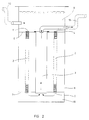
- a battery 1 for an arrangement according to the invention consists of a number of lengths of pipe 2 wound helically, layer upon layer, round a central pipe 3 in the middle.
- the pipe ends 4, 5 and the central pipe 3 are connected watertight to end covers 6 and 7, respectively.
- the battery 1 is mounted in a vessel 8 so that the end covers 6, 7 seal watertight to the inside of the wall of the vessel 8. As illustrated, the battery 1 is located in the vessel 8 so that the space above the battery 1 contains a reservoir 9 and below the battery another space 10, which as shown in fig. 4 can be embodied as a reservoir.
- Water resistance in the pipes 2 is so adjusted to the pressure head above the arrangement so that all the pipe openings 11 are covered with a water table. This ensures an even distribution of the water to all pipes 2.
- the water volume flowing through the system, Q m3/h is apportioned to the total swept surface area, F m2, by the pipes 2 in relation to the affinity to water of the impurities.
- the raw waste water enters the reservoir 9 through a pipe 12.
- the water passes internally through the pipes 2 and at the bottom of reservoir 10 it enters the central pipe 3 in the middle of the vessel from whose top purified waste water is discharged through the outlet pipe 13.
- the embodiment shown in fig. 2 is well suited as an oil separator.
- the oil is separated as pearls rising obliquely against the counter-flow of the water and collects at the surface where it can be skimmed off or otherwise removed.
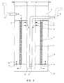
- the embodiment shown in fig. 3 can also be used as an oil separator.
- the central pipe 3 is carried right to the top of the reservoir 9 which is thus divided into an external annular zone and an internal zone in the pipe 3.
- the water enters the external zone through a pipe 12.
- the reservoir 9 is almost full up with water.
- the water passes internally through the pipes 2 to a bottom reservoir 10, from which it continues through openings 14 in the bottom end cover 7.
- the arrangement can be designed according to the N-pump principle as described in the applicant's patent application HEP-A-0410923.
- the upper reservoir 9 is closed with a cover 18 at the top.
- the reservoir can be put under pressure by means of a blower 19, which is connected to the reservoir by a pipe 20 which opens under the cover 18, and it can be ventilated by means of a venting valve 21, e.g. a magnetic valve, which is connected to the reservoir through a pipe 22, ending under the cover 18.
- a venting valve 21 e.g. a magnetic valve
- water When the system is vented, water will be sent - e.g. from a sludge treatment plant - through a feeder pipe 12, which by means of a T-branch 23 is connected to the initial pipe 24 mounted inside the central pipe 3 and extending a distance down into the reservoir 10. The water is then forced up through the pipes 2 in the battery 1 and taken through openings 25 over an intermediate bottom 26 to the upper pipe opening 27 of the pipe 13.
Landscapes
- Chemical & Material Sciences (AREA)
- Chemical Kinetics & Catalysis (AREA)
- Physics & Mathematics (AREA)
- Thermal Sciences (AREA)
- Removal Of Floating Material (AREA)
- Hybrid Cells (AREA)
- Physical Water Treatments (AREA)
Applications Claiming Priority (3)
| Application Number | Priority Date | Filing Date | Title |
|---|---|---|---|
| DK2199/90 | 1990-09-14 | ||
| DK219990A DK166773B1 (da) | 1990-09-14 | 1990-09-14 | Anordning til rensning af spildevand |
| PCT/DK1991/000263 WO1992004959A1 (en) | 1990-09-14 | 1991-09-11 | Arrangement for purification of waste water |
Publications (2)
| Publication Number | Publication Date |
|---|---|
| EP0549650A1 EP0549650A1 (en) | 1993-07-07 |
| EP0549650B1 true EP0549650B1 (en) | 1995-01-25 |
Family
ID=8110744
Family Applications (1)
| Application Number | Title | Priority Date | Filing Date |
|---|---|---|---|
| EP91916609A Expired - Lifetime EP0549650B1 (en) | 1990-09-14 | 1991-09-11 | Arrangement for purification of waste water |
Country Status (7)
| Country | Link |
|---|---|
| EP (1) | EP0549650B1 (da) |
| AU (1) | AU8631691A (da) |
| DE (1) | DE69107085T2 (da) |
| DK (1) | DK166773B1 (da) |
| ES (1) | ES2070509T3 (da) |
| PL (1) | PL168708B1 (da) |
| WO (1) | WO1992004959A1 (da) |
Families Citing this family (1)
| Publication number | Priority date | Publication date | Assignee | Title |
|---|---|---|---|---|
| DE19726488A1 (de) * | 1997-06-21 | 1998-12-24 | Michael Benkeser | Flüssigkeitsabscheider |
Family Cites Families (2)
| Publication number | Priority date | Publication date | Assignee | Title |
|---|---|---|---|---|
| NL140421B (nl) * | 1965-11-08 | 1973-12-17 | Mitsubishi Heavy Ind Ltd | Inrichting voor het afscheiden van gedispergeerde stoffen uit een vloeibare dispersie. |
| US4855050A (en) * | 1984-09-10 | 1989-08-08 | Senyard Sr Corley P | Centrifugal oil separator for removing oil from a waste flowing stream |
-
1990
- 1990-09-14 DK DK219990A patent/DK166773B1/da not_active IP Right Cessation
-
1991
- 1991-09-11 EP EP91916609A patent/EP0549650B1/en not_active Expired - Lifetime
- 1991-09-11 PL PL91294506A patent/PL168708B1/pl unknown
- 1991-09-11 WO PCT/DK1991/000263 patent/WO1992004959A1/en not_active Ceased
- 1991-09-11 ES ES91916609T patent/ES2070509T3/es not_active Expired - Lifetime
- 1991-09-11 DE DE69107085T patent/DE69107085T2/de not_active Expired - Fee Related
- 1991-09-11 AU AU86316/91A patent/AU8631691A/en not_active Abandoned
Also Published As
| Publication number | Publication date |
|---|---|
| ES2070509T3 (es) | 1995-06-01 |
| DK219990A (da) | 1992-03-15 |
| AU8631691A (en) | 1992-04-15 |
| PL168708B1 (pl) | 1996-03-29 |
| WO1992004959A1 (en) | 1992-04-02 |
| DE69107085T2 (de) | 1995-09-07 |
| DE69107085D1 (de) | 1995-03-09 |
| DK166773B1 (da) | 1993-07-12 |
| DK219990D0 (da) | 1990-09-14 |
| EP0549650A1 (en) | 1993-07-07 |
Similar Documents
| Publication | Publication Date | Title |
|---|---|---|
| CA1325179C (en) | Oil-water separator | |
| US4202778A (en) | Separating device | |
| US5788848A (en) | Apparatus and methods for separating solids from flowing liquids or gases | |
| EP0046070A2 (en) | A separator | |
| US5593584A (en) | Septic tank filter | |
| EP0642817A1 (en) | Settling unit with plate separator | |
| EP0003859A1 (en) | A device for treating waste water | |
| US4213865A (en) | Apparatus for separating sludge, oil and the like from contaminated water | |
| US4595504A (en) | Lamella sedimentation device | |
| EP0549650B1 (en) | Arrangement for purification of waste water | |
| GB2019238A (en) | Separating oil and water | |
| HUT69510A (en) | Settling tank with oil separator | |
| AU2011298805B2 (en) | Separator for separating a light liquid-water mixture and method for separating a light liquid-water mixture | |
| GB2195554A (en) | Ridged plate separator | |
| CA2085274C (en) | Sedimentation device | |
| EP1270055A2 (de) | Schlamm- und Ölabscheider für Abwasser | |
| JPH039761Y2 (da) | ||
| KR200220552Y1 (ko) | 유수분리기용 유수분리판 | |
| JPS60122010A (ja) | 船舶用油水分離装置 | |
| KR820000226Y1 (ko) | 유수 분리기 | |
| RU1801545C (ru) | Устройство дл сброса поверхностного сло воды из отстойника | |
| JPH0220002Y2 (da) | ||
| SU1223999A1 (ru) | Каплеуловитель | |
| JPS6327064B2 (da) | ||
| HRP950003A2 (en) | Sludge and oil separator for waste water |
Legal Events
| Date | Code | Title | Description |
|---|---|---|---|
| PUAI | Public reference made under article 153(3) epc to a published international application that has entered the european phase |
Free format text: ORIGINAL CODE: 0009012 |
|
| 17P | Request for examination filed |
Effective date: 19930416 |
|
| AK | Designated contracting states |
Kind code of ref document: A1 Designated state(s): CH DE ES GB GR IT LI NL SE |
|
| R17P | Request for examination filed (corrected) |
Effective date: 19930413 |
|
| 17Q | First examination report despatched |
Effective date: 19940705 |
|
| GRAA | (expected) grant |
Free format text: ORIGINAL CODE: 0009210 |
|
| AK | Designated contracting states |
Kind code of ref document: B1 Designated state(s): CH DE ES GB GR IT LI NL SE |
|
| PG25 | Lapsed in a contracting state [announced via postgrant information from national office to epo] |
Ref country code: NL Effective date: 19950125 Ref country code: GR Free format text: LAPSE BECAUSE OF FAILURE TO SUBMIT A TRANSLATION OF THE DESCRIPTION OR TO PAY THE FEE WITHIN THE PRESCRIBED TIME-LIMIT Effective date: 19950125 |
|
| REF | Corresponds to: |
Ref document number: 69107085 Country of ref document: DE Date of ref document: 19950309 |
|
| ITF | It: translation for a ep patent filed | ||
| REG | Reference to a national code |
Ref country code: ES Ref legal event code: FG2A Ref document number: 2070509 Country of ref document: ES Kind code of ref document: T3 |
|
| NLV1 | Nl: lapsed or annulled due to failure to fulfill the requirements of art. 29p and 29m of the patents act | ||
| PGFP | Annual fee paid to national office [announced via postgrant information from national office to epo] |
Ref country code: CH Payment date: 19950906 Year of fee payment: 5 |
|
| PGFP | Annual fee paid to national office [announced via postgrant information from national office to epo] |
Ref country code: DE Payment date: 19950930 Year of fee payment: 5 |
|
| PLBE | No opposition filed within time limit |
Free format text: ORIGINAL CODE: 0009261 |
|
| STAA | Information on the status of an ep patent application or granted ep patent |
Free format text: STATUS: NO OPPOSITION FILED WITHIN TIME LIMIT |
|
| 26N | No opposition filed | ||
| PG25 | Lapsed in a contracting state [announced via postgrant information from national office to epo] |
Ref country code: LI Effective date: 19960930 Ref country code: CH Effective date: 19960930 |
|
| REG | Reference to a national code |
Ref country code: CH Ref legal event code: PL |
|
| PG25 | Lapsed in a contracting state [announced via postgrant information from national office to epo] |
Ref country code: DE Effective date: 19970603 |
|
| PGFP | Annual fee paid to national office [announced via postgrant information from national office to epo] |
Ref country code: GB Payment date: 19980821 Year of fee payment: 8 |
|
| PGFP | Annual fee paid to national office [announced via postgrant information from national office to epo] |
Ref country code: SE Payment date: 19980827 Year of fee payment: 8 |
|
| PG25 | Lapsed in a contracting state [announced via postgrant information from national office to epo] |
Ref country code: GB Free format text: LAPSE BECAUSE OF NON-PAYMENT OF DUE FEES Effective date: 19990911 |
|
| PG25 | Lapsed in a contracting state [announced via postgrant information from national office to epo] |
Ref country code: SE Free format text: THE PATENT HAS BEEN ANNULLED BY A DECISION OF A NATIONAL AUTHORITY Effective date: 19990929 |
|
| GBPC | Gb: european patent ceased through non-payment of renewal fee |
Effective date: 19990911 |
|
| EUG | Se: european patent has lapsed |
Ref document number: 91916609.0 |
|
| PGFP | Annual fee paid to national office [announced via postgrant information from national office to epo] |
Ref country code: ES Payment date: 20000901 Year of fee payment: 10 |
|
| PG25 | Lapsed in a contracting state [announced via postgrant information from national office to epo] |
Ref country code: ES Free format text: LAPSE BECAUSE OF NON-PAYMENT OF DUE FEES Effective date: 20010912 |
|
| REG | Reference to a national code |
Ref country code: ES Ref legal event code: FD2A Effective date: 20021011 |
|
| PG25 | Lapsed in a contracting state [announced via postgrant information from national office to epo] |
Ref country code: IT Free format text: LAPSE BECAUSE OF NON-PAYMENT OF DUE FEES;WARNING: LAPSES OF ITALIAN PATENTS WITH EFFECTIVE DATE BEFORE 2007 MAY HAVE OCCURRED AT ANY TIME BEFORE 2007. THE CORRECT EFFECTIVE DATE MAY BE DIFFERENT FROM THE ONE RECORDED. Effective date: 20050911 |