EP0549548B2 - Drill - Google Patents
Drill Download PDFInfo
- Publication number
- EP0549548B2 EP0549548B2 EP92850261A EP92850261A EP0549548B2 EP 0549548 B2 EP0549548 B2 EP 0549548B2 EP 92850261 A EP92850261 A EP 92850261A EP 92850261 A EP92850261 A EP 92850261A EP 0549548 B2 EP0549548 B2 EP 0549548B2
- Authority
- EP
- European Patent Office
- Prior art keywords
- zone
- flute
- width
- chipforming
- tip
- Prior art date
- Legal status (The legal status is an assumption and is not a legal conclusion. Google has not performed a legal analysis and makes no representation as to the accuracy of the status listed.)
- Expired - Lifetime
Links
Images

Classifications
-
- B—PERFORMING OPERATIONS; TRANSPORTING
- B23—MACHINE TOOLS; METAL-WORKING NOT OTHERWISE PROVIDED FOR
- B23B—TURNING; BORING
- B23B51/00—Tools for drilling machines
- B23B51/02—Twist drills
-
- B—PERFORMING OPERATIONS; TRANSPORTING
- B23—MACHINE TOOLS; METAL-WORKING NOT OTHERWISE PROVIDED FOR
- B23B—TURNING; BORING
- B23B2240/00—Details of connections of tools or workpieces
- B23B2240/08—Brazed connections
-
- B—PERFORMING OPERATIONS; TRANSPORTING
- B23—MACHINE TOOLS; METAL-WORKING NOT OTHERWISE PROVIDED FOR
- B23B—TURNING; BORING
- B23B2250/00—Compensating adverse effects during turning, boring or drilling
- B23B2250/12—Cooling and lubrication
-
- B—PERFORMING OPERATIONS; TRANSPORTING
- B23—MACHINE TOOLS; METAL-WORKING NOT OTHERWISE PROVIDED FOR
- B23B—TURNING; BORING
- B23B2251/00—Details of tools for drilling machines
- B23B2251/24—Overall form of drilling tools
- B23B2251/241—Cross sections of the diameter of the drill
-
- B—PERFORMING OPERATIONS; TRANSPORTING
- B23—MACHINE TOOLS; METAL-WORKING NOT OTHERWISE PROVIDED FOR
- B23B—TURNING; BORING
- B23B2251/00—Details of tools for drilling machines
- B23B2251/40—Flutes, i.e. chip conveying grooves
- B23B2251/406—Flutes, i.e. chip conveying grooves of special form not otherwise provided for
-
- B—PERFORMING OPERATIONS; TRANSPORTING
- B23—MACHINE TOOLS; METAL-WORKING NOT OTHERWISE PROVIDED FOR
- B23B—TURNING; BORING
- B23B2251/00—Details of tools for drilling machines
- B23B2251/50—Drilling tools comprising cutting inserts
-
- Y—GENERAL TAGGING OF NEW TECHNOLOGICAL DEVELOPMENTS; GENERAL TAGGING OF CROSS-SECTIONAL TECHNOLOGIES SPANNING OVER SEVERAL SECTIONS OF THE IPC; TECHNICAL SUBJECTS COVERED BY FORMER USPC CROSS-REFERENCE ART COLLECTIONS [XRACs] AND DIGESTS
- Y10—TECHNICAL SUBJECTS COVERED BY FORMER USPC
- Y10T—TECHNICAL SUBJECTS COVERED BY FORMER US CLASSIFICATION
- Y10T408/00—Cutting by use of rotating axially moving tool
- Y10T408/89—Tool or Tool with support
- Y10T408/909—Having peripherally spaced cutting edges
- Y10T408/9095—Having peripherally spaced cutting edges with axially extending relief channel
- Y10T408/9097—Spiral channel
Definitions
- the present invention relates to a drill comprising a substantially solid shank with a first tipforming end including one or several cutting edges for cutting machining of preferably metallic workpieces in order to make holes in these, an opposite second end, and a number of flutes corresponding to the number of cutting edges, extending from the tip end towards the other end, having the purpose of forming and removing chips from the corresponding cutting edge (see JP-A-63-260 713).
- the flutes of, e.g., a twist drill have two important functions, viz. on the one hand the forming of chips (including chipbreaking) and on the other hand the removal of these formed chips.
- the chip formation occurs in a space immediately behind each cutting edge, irrespectively of whether said edge is formed by a sharpening of the drill top as such, or by a separate cutting insert which is fastened on the tip by, e.g., brazing.
- the initially bandlike material that is separated off by the cutting edge from a workpiece is forced to curl and break, thus creating separate chips with a particular form and size.
- chips of limited length are produced which are specifically formed by the geometry, for instance conical or bell-like chips.
- the form and the size of the chipforming space in each flute have great importance in order to achieve a form and a size of the chips that make them easily conveyable.
- the chip After having been formed and broken, the chip possesses an inherent elasticity that varies from material to material, but which always implies a striving of the chip to dilate by elastic deformation, thereby exerting a more or less strong pressure upon the flute walls and also against the walls of the hole being drilled in the workpiece.
- the chipconveying flutes normally have one and the same width along their entire longitudinal extension. This implies that the pressure of the chip against the hole wall remains substantially equal along the entire length of the flute. If this pressure is sufficiently high, the total friction force of many chips can cause chip jamming with considerable inconveniences as a consequence. Even if occurring chip jamming does not necessarily cause a tool breakdown, it can anyway severely disturb the chipforming.
- the chips will get folded and will stiffen, thereby forming long, bandiron-like configurations which are difficult to convey.
- chip jamming thus severely complicates the conveyance of the chips and sometimes the friction between the chips and the hole wall can result in an extremely high generation of heat and in an uneven hole surface.
- An extraordinary high friction naturally also leads to the drill being forced to work with a high turning resistance.
- a primary object of the invention is to provide a drill with improved chip-conveying ability in comparison with conventional drills. Another object is to bring about this improved chip-conveying ability by simple means and by minimal economical contribution.
- the effect is achieved that the chips can be formed under ideal circumstances in the first zone and immediately thereafter dilate in the following conveying zone under great decrease of the friction between the chips and the hole wall.
- the chips will thus be effectively pressed together into typical chips with optimal form in the chipforming zone, which can have the same optimal form for different drill types as the corresponding conventional drill of the same type, after which the inherent.spring force in the chip is liberated in the following conveying zone with enlarged width.
- the sum of the length a of zone 12 and the length b of conveying zone 13 equals the total length c of the flute.
- the flute has one and the same width or cross-sectional area along the whole length b of its conveying zone 13, i.e. the flute has a uniform depth in this zone.
- the widening of the flute in the conveying zone 13 takes place at the expense of the stiffness and the strength of the drill shank, since the core 5 of the shank (cf. figures 5 and 6) becomes thinner in the region of the widened chip-conveying zones 13 than in the region of the narrower zone 12.
- the flute depth in the conveying zone 13 is determined by a compromise between on the one hand the requirement of stiffness in the shank and on the other hand the desire of a possibly roomy chip-conveying space.
- the possibility is foreseen of making the chip-conveying zone 13 of the flute with a varying cross-sectional area, more specifically in such a way that the flute, at least along a rear part of zone 13, has a gradually decreasing width towards the rear end of the shaft, up to a width that is not smaller than the smallest width of the chiptorming zone 12.
- Such an embodiment can be realized since the chips are more easily conveyed from the flutes in the region of their rear, open end than in the region closer to the tip, where chips lying behind exert a higher conveying resistance.
- the zone connection 14 should have the form of a distinct step, after which the flute width abruptly increases in the conveying zone.
- this step is suitably achieved by letting a radial shank-end mill, which has been used for forming the conveying zone, be taken out sidewise after performed milling, while leaving a rounded end surface.
- the axial extension of connection 14 does not become larger than the radial measure of the flute depression.
- the bottom 15 of the flute in forming zone 12 is indicated by broken lines, while the bottom of the flute in conveying zone 13 is designated 15'.
- the distance between the continuous and the broken lines represent the measure by which the flute widens in the conveying zone.
- the depression is substantially equally large over the whole width of the flute.
- the invention does not exclude the possibility of widening the flute by either only one depression (while maintaining the same width as in forming zone 12) or only one widening (while maintaining the same depth as in the forming zone).
- fig 7 an alternative embodiment of the drills is shown, which differs from the embodiment in fig 6 in that the individual flute 7, 7' in its chip-conveying zone 13 at least partially is delimited by a bottom or a surface in which are provided longitudinal depressions or grooves 17 between which there are ridges, preferably sharp edged ridges 18, which have the purpose of reducing the contact surfaces between the chips and the flute.
- the chip conveyance is thus not only facilitated by the fact that the flute has been widened in its chip-forming zone 13 but also by the sharp ridges 18 which bring about a line contact between chips and flute bottom, rather than a surface contact as when the flutes have a completely smooth bottom.
- each of the two flutes 7, 7' are widened in their conveying zones 13 in that a longitudinal depression 19, 19' with a smaller width than the flute's total width has been positioned excentrically or unsymmetrically in the flute bottom (such a thin depression may also be positioned centrally in the flute bottom).
- Lately drills have been developed whose shanks are divided into a main part and a tip part which is disconnectable from the former and on which the cutting edge(s) is/are positioned, normally in the form of separate cutting inserts which have been soldered onto the tip part.
- the present invention can advantageously also be applied on such drills, the connection between the chipforming zone and the chip-conveying zone in each flute being located to the joint region of said main part and tip part.
- the chipforming zone is exclusively in the tip part, while the pure chipconveying zone is in the main part of the shank.
- the invention is not restricted solely to the embodiments as described and shown on the drawings. It is also possible to apply the invention on other drills than twist drills and twist drills with two chipconveying flutes. Thus, the invention can also be applied on drills with straight chipconveying flutes. Nor is the realization of the invention dependent upon the number of flutes in each drill. Hence, the chip conveyance can be improved in the described way independently of whether the shank comprises one or more flutes.
- drills known from US 750,537 and W089/02328 lack distinct chipforming and conveying zones with different widths which are connected via a distinct joint.
- JP-A-63-260 713 a blank for extra-hard solid drills is disclosed whose core thickness is greater in the neighborhood of the tip than in the main part of the shaft. This has the consequence that the flute width at the tip is smaller than in the shaft. However, the flute width of the front chip forming zone is substantially constant and does not bring about the benificial, initial chip compression according to the present invention.
- FIG. 1 generally designates a solid shank with a first end on tip 2 and an opposite second end 3.
- the shank of the shown embodiment has a thicker part 4 suitable for inserting into a holder.
- a core 5 in Fig 5 and 6) two lands 6, 6' protrude, which delimit two flutes 7, 7'.
- the drill is a twist drill on which the lands 6, 6' as well as the flutes 7, 7' extend helically around the longitudinal axis of the shank. In practice these flutes in known manner have a suitably uniform pitch angle within the range 20-40°.
- two cutting edges 8, 8' are provided, which in this case are formed on special cutting inserts 9, 9' that have been fixed to the tip in a suitable way, for instance by soldering.
- the cutting inserts 9, 9' are placed in such a way that they meet at the center of the drill.
- these cutting edges could equally well be formed by grinding of suitably formed surfaces on the shank per se or on a part which is connect- and disconnectable with the shank.
- shank 1 can be provided with one or more ducts 10, 10' (see fig 5) which lead to two openings 11,11' in the proximity of the cutting edges 8, 8'. In known manner a cooling medium can be fed through these ducts to the drill's tip.
- solid shank as used in the present description and in the following claims has the purpose of distinguishing the drill according to the invention from such drills that include pipe-formed shanks, but does not exclude such shanks which have one or several diminutive ducts for a cooling medium in an otherwise solid body.
- Fig 2 illustrates the appearance of a normally occurring individual chip that has been formed by the drill according to Fig 1.
- Each of the two flutes 7, 7' is divided into on the one hand a first, chipforming zone 12, and on the other hand a second, merely chip-conveying zone 13 with a larger width or cross-sectional area than the former zone.
- the connection 14 between these two zones 12, 13 has the form of a distinct step whose depth determines the differences in width at the connection between the two zones,
- the individual flute in known manner preferably has an arc-like cross-sectional form, for instance the form of a circular arc (see fig 5), i.e. it is delimited by an arched, smooth surface 15 that extends between the two limit edges 16, 16' on the two lands 6, 6' between which the flute is delimited.
- the length a of the chipforming zone 12, starting from the shank's tip 2, should lie within the range 0,3-2,0, suitably 0,5-1,5 or preferably around 0,8 times the shank's diameter.
- This length in combination with the cross-sectional form of the flute in zone 12 is established from case to case for different types of drills, depending on, e.g., the drill diameter, the length of the drill, the material properties of the workpieces, etc; all aiming at achieving ideal chipforming in the zone.
- the individual flute 7, 7' in its chipforming zone 12 has substantially one and the same width along the entire extension of said zone, i.e., a line at the bottom of the flute extends steadily on the same distance from the central axis of the shank in this zone (possibly with the exception of a short recess or depression in the flute surface in the immediate proximity of the region of the tip where the two cutting inserts 9, 9' meet).
- the chipforming zone is construed in such a way that the flute at least in a rear part of this zone has a rearwards gradually decreasing width, whereby in the region of the connection or step 14 a passage is created with minimal width in which the chips will be compressed to an extraordinarily small volume before they are fed into the conveying zone 13 and dilate. It is possible to achieve an extraordinary compression of the chips in this way because the compression takes place only in a space with a very limited axial extension.
Abstract
Description
- The present invention relates to a drill comprising a substantially solid shank with a first tipforming end including one or several cutting edges for cutting machining of preferably metallic workpieces in order to make holes in these, an opposite second end, and a number of flutes corresponding to the number of cutting edges, extending from the tip end towards the other end, having the purpose of forming and removing chips from the corresponding cutting edge (see JP-A-63-260 713).
- The flutes of, e.g., a twist drill, have two important functions, viz. on the one hand the forming of chips (including chipbreaking) and on the other hand the removal of these formed chips. The chip formation occurs in a space immediately behind each cutting edge, irrespectively of whether said edge is formed by a sharpening of the drill top as such, or by a separate cutting insert which is fastened on the tip by, e.g., brazing. In this front space of a flute, the initially bandlike material that is separated off by the cutting edge from a workpiece, is forced to curl and break, thus creating separate chips with a particular form and size. Under ideal circumstances, which are determined by several different factors, like the material properties of the workpiece, cutting geometry, the diameter of the drill, the form and relative dimensions of the chipforming space, etc, chips of limited length are produced which are specifically formed by the geometry, for instance conical or bell-like chips. Particularly the form and the size of the chipforming space in each flute have great importance in order to achieve a form and a size of the chips that make them easily conveyable.
- After having been formed and broken, the chip possesses an inherent elasticity that varies from material to material, but which always implies a striving of the chip to dilate by elastic deformation, thereby exerting a more or less strong pressure upon the flute walls and also against the walls of the hole being drilled in the workpiece. By conventional prior art drills, the chipconveying flutes normally have one and the same width along their entire longitudinal extension. This implies that the pressure of the chip against the hole wall remains substantially equal along the entire length of the flute. If this pressure is sufficiently high, the total friction force of many chips can cause chip jamming with considerable inconveniences as a consequence. Even if occurring chip jamming does not necessarily cause a tool breakdown, it can anyway severely disturb the chipforming. Instead of getting an ideal form, the chips will get folded and will stiffen, thereby forming long, bandiron-like configurations which are difficult to convey. Such chip jamming thus severely complicates the conveyance of the chips and sometimes the friction between the chips and the hole wall can result in an extremely high generation of heat and in an uneven hole surface. An extraordinary high friction naturally also leads to the drill being forced to work with a high turning resistance.
- The above mentioned inconveniences are of course specially pronounced for longhole drills (i.e. drills whose length are 8 to 10 times or more longer than their diameters), which sometimes can have very long chip-conveying flutes, in which the total pressure of all the chips that have been pressed together is extraordinarily high.
- The present invention aims at eliminating or reducing the above related inconveniences of known drills. Thus, a primary object of the invention is to provide a drill with improved chip-conveying ability in comparison with conventional drills. Another object is to bring about this improved chip-conveying ability by simple means and by minimal economical contribution.
- According to the invention, the above-mentioned objects are achieved with a drill in accordance with
claim 1. - By dividing the individual chip-conveying flute into on the one hand a pronounced chipforming zone and on the other hand into another zone for only chip conveyance with larger width than the chipforming zone, the effect is achieved that the chips can be formed under ideal circumstances in the first zone and immediately thereafter dilate in the following conveying zone under great decrease of the friction between the chips and the hole wall. In practice the chips will thus be effectively pressed together into typical chips with optimal form in the chipforming zone, which can have the same optimal form for different drill types as the corresponding conventional drill of the same type, after which the inherent.spring force in the chip is liberated in the following conveying zone with enlarged width.
- Many attempts have been made in the prior art with the aim to improve the chip-conveying function of drills. E.g., from CH 665,979 and DE 2,459,286 it is known to make the helically formed.chip-conveying flutes of twist drills with diminishing twist angle, e.g., with increasing pitch angle, towards the rear end of the drill shank, in order to give the flutes a progressively increasing width from the tip end towards the rear end. However, in this case there is no pronounced chipforming zone which connects with a recessed or widened conveying zone via a distinct step, but rather a continuous smooth diminution of the twist angle the whole way from the tip of the shank.
- Further, in DE 1,477,719 a drill is described with one single, straight chip flute with continuously increasing radial depth from the tip towards a point at a considerable distance from the tip. Nor is there in this case any pronounced chipforming zone that gives a distinct compressed chip which after forming can dilate in a specific conveying zone with abruptly increasing width. let the flute connect to a zone of the same width as the zone 12). In practice the increase of the flute width in the
conveying zone 13 should lie within the range 5-25 %, suitably 10-20 %, i.e., the cross-sectional area in theconveying zone 13 should be 5-25 % or 10-20 % larger than the cross-sectional area in the formingzone 12. In this case, the sum of the length a ofzone 12 and the length b ofconveying zone 13 equals the total length c of the flute. According to a preferred embodiment the flute has one and the same width or cross-sectional area along the whole length b of itsconveying zone 13, i.e. the flute has a uniform depth in this zone. However, the widening of the flute in theconveying zone 13 takes place at the expense of the stiffness and the strength of the drill shank, since thecore 5 of the shank (cf. figures 5 and 6) becomes thinner in the region of the widened chip-conveying zones 13 than in the region of thenarrower zone 12. Therefore, in practice the flute depth in theconveying zone 13 is determined by a compromise between on the one hand the requirement of stiffness in the shank and on the other hand the desire of a possibly roomy chip-conveying space. In view of this, the possibility is foreseen of making the chip-conveying zone 13 of the flute with a varying cross-sectional area, more specifically in such a way that the flute, at least along a rear part ofzone 13, has a gradually decreasing width towards the rear end of the shaft, up to a width that is not smaller than the smallest width of thechiptorming zone 12. Such an embodiment can be realized since the chips are more easily conveyed from the flutes in the region of their rear, open end than in the region closer to the tip, where chips lying behind exert a higher conveying resistance. - A previously mentioned, the
zone connection 14 should have the form of a distinct step, after which the flute width abruptly increases in the conveying zone. In practice this step is suitably achieved by letting a radial shank-end mill, which has been used for forming the conveying zone, be taken out sidewise after performed milling, while leaving a rounded end surface. In this case the axial extension ofconnection 14 does not become larger than the radial measure of the flute depression. However, it is also feasible - although not preferred - to make a connection with a larger axial extension than this. - In fig 6 the
bottom 15 of the flute in formingzone 12 is indicated by broken lines, while the bottom of the flute inconveying zone 13 is designated 15'. The distance between the continuous and the broken lines represent the measure by which the flute widens in the conveying zone. In the shown embodiment the depression is substantially equally large over the whole width of the flute. However, the invention does not exclude the possibility of widening the flute by either only one depression (while maintaining the same width as in forming zone 12) or only one widening (while maintaining the same depth as in the forming zone). - In fig 7 an alternative embodiment of the drills is shown, which differs from the embodiment in fig 6 in that the
individual flute 7, 7' in its chip-conveying zone 13 at least partially is delimited by a bottom or a surface in which are provided longitudinal depressions orgrooves 17 between which there are ridges, preferably sharpedged ridges 18, which have the purpose of reducing the contact surfaces between the chips and the flute. In this case the chip conveyance is thus not only facilitated by the fact that the flute has been widened in its chip-formingzone 13 but also by thesharp ridges 18 which bring about a line contact between chips and flute bottom, rather than a surface contact as when the flutes have a completely smooth bottom. - In fig 8 a further embodiment is shown, according to which each of the two
flutes 7, 7' are widened in theirconveying zones 13 in that alongitudinal depression 19, 19' with a smaller width than the flute's total width has been positioned excentrically or unsymmetrically in the flute bottom (such a thin depression may also be positioned centrally in the flute bottom). - Lately drills have been developed whose shanks are divided into a main part and a tip part which is disconnectable from the former and on which the cutting edge(s) is/are positioned, normally in the form of separate cutting inserts which have been soldered onto the tip part. The present invention can advantageously also be applied on such drills, the connection between the chipforming zone and the chip-conveying zone in each flute being located to the joint region of said main part and tip part. Thus, the chipforming zone is exclusively in the tip part, while the pure chipconveying zone is in the main part of the shank.
- When the chip, like in the case of the machining of most metals, have an inherent elasticity after having been formed in the
first zone 12, they are given an opportunity of dilating in the followingconveying zone 13. By proceeding in this way the friction-increasing force is considerably reduced, with which the chips, as a consequence of their elasticity, tend to press against the walls of the flutes, as well as the walls of the hole which is being drilled in the actual workpiece. This results in a radical decrease of the chip-conveying resistance under simultaneous diminution of heat generation, whereby also the turn resistance is reduced and smoother hole surfaces are obtained. - Obviously the invention is not restricted solely to the embodiments as described and shown on the drawings. It is also possible to apply the invention on other drills than twist drills and twist drills with two chipconveying flutes. Thus, the invention can also be applied on drills with straight chipconveying flutes. Nor is the realization of the invention dependent upon the number of flutes in each drill. Hence, the chip conveyance can be improved in the described way independently of whether the shank comprises one or more flutes.
- Also the drills known from US 750,537 and W089/02328 lack distinct chipforming and conveying zones with different widths which are connected via a distinct joint.
- In JP-A-63-260 713 a blank for extra-hard solid drills is disclosed whose core thickness is greater in the neighborhood of the tip than in the main part of the shaft. This has the consequence that the flute width at the tip is smaller than in the shaft. However, the flute width of the front chip forming zone is substantially constant and does not bring about the benificial, initial chip compression according to the present invention.
- On the drawings are:
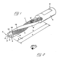
- Fig 1 a perspective view of a drill embodying the present invention,
- Fig 2 a simplified and amplified perspective view illustrating the general form of an individual chip formed by the drill as shown in Fig 1,
- Fig 3 a side view of the same drill as in Fig 1.
- Fig 4 an end view of the tip end of the drill,
- Fig 5 an amplified cross-sectional view taken along line V-V in the region of the tip of the drill-shaft,
- Fig 6 an analogous, amplified cross-sectional view taken along line VI-VI through that part of the shank in which the widened chipforming zone is provided,
- Fig 7 a similar cross-sectional view showing an alternative embodiment of the chip-conveying flutes in their conveying zone, and
- Fig 8 a cross-sectional view showing a further alternative form of the flutes in their conveying zone.
-
- In the
drawings 1 generally designates a solid shank with a first end ontip 2 and an oppositesecond end 3. - At this second, rear end the shank of the shown embodiment has a
thicker part 4 suitable for inserting into a holder. From a core (5 in Fig 5 and 6) twolands 6, 6' protrude, which delimit twoflutes 7, 7'. In the shown embodiment the drill is a twist drill on which thelands 6, 6' as well as theflutes 7, 7' extend helically around the longitudinal axis of the shank. In practice these flutes in known manner have a suitably uniform pitch angle within the range 20-40°. At thetip 2 twocutting edges 8, 8' are provided, which in this case are formed on special cutting inserts 9, 9' that have been fixed to the tip in a suitable way, for instance by soldering. The cutting inserts 9, 9' are placed in such a way that they meet at the center of the drill. However, these cutting edges could equally well be formed by grinding of suitably formed surfaces on the shank per se or on a part which is connect- and disconnectable with the shank. It should also be noted thatshank 1 can be provided with one ormore ducts 10, 10' (see fig 5) which lead to twoopenings 11,11' in the proximity of thecutting edges 8, 8'. In known manner a cooling medium can be fed through these ducts to the drill's tip. The term "solid shank" as used in the present description and in the following claims has the purpose of distinguishing the drill according to the invention from such drills that include pipe-formed shanks, but does not exclude such shanks which have one or several diminutive ducts for a cooling medium in an otherwise solid body. - Fig 2 illustrates the appearance of a normally occurring individual chip that has been formed by the drill according to Fig 1.
- Each of the two
flutes 7, 7' is divided into on the one hand a first,chipforming zone 12, and on the other hand a second, merely chip-conveyingzone 13 with a larger width or cross-sectional area than the former zone. Theconnection 14 between these twozones smooth surface 15 that extends between the twolimit edges 16, 16' on the twolands 6, 6' between which the flute is delimited. The length a of the chipformingzone 12, starting from the shank'stip 2, should lie within the range 0,3-2,0, suitably 0,5-1,5 or preferably around 0,8 times the shank's diameter. This length in combination with the cross-sectional form of the flute inzone 12 is established from case to case for different types of drills, depending on, e.g., the drill diameter, the length of the drill, the material properties of the workpieces, etc; all aiming at achieving ideal chipforming in the zone. - According to one embodiment not embodying the invention, the
individual flute 7, 7' in itschipforming zone 12 has substantially one and the same width along the entire extension of said zone, i.e., a line at the bottom of the flute extends steadily on the same distance from the central axis of the shank in this zone (possibly with the exception of a short recess or depression in the flute surface in the immediate proximity of the region of the tip where the two cuttinginserts 9, 9' meet). However, according to an embodiment of the invention the chipforming zone is construed in such a way that the flute at least in a rear part of this zone has a rearwards gradually decreasing width, whereby in the region of the connection or step 14 a passage is created with minimal width in which the chips will be compressed to an extraordinarily small volume before they are fed into the conveyingzone 13 and dilate. It is possible to achieve an extraordinary compression of the chips in this way because the compression takes place only in a space with a very limited axial extension. - The conveying
zone 13, which is widened in relation withchipforming zone 12, advantageously extends the whole way from theconnection 14 to the rear end of the flute (although it is also feasible to end thezone 13 at certain distance from the rear end of the flute and again
Claims (9)
- Drill comprising a substantially solid shank (1) with a first, tipforming end (2) having one or more cutting edges (8, 8') for cutting machining of preferably metallic workpieces, aiming at making holes in these, an opposite second end (3) and a number of flutes (7, 7') corresponding to the number of cutting edges, which extend from the tip end (2) towards the other end (3), and having as object to form and convey chips from the corresponding cutting edge, characterized in that said flutes (7, 7') on a certain distance from the tip end (2) turn from a first, chipforming zone (12) with a certain width or cross-sectional area into a second, merely chip-conveying zone (13) with larger width or cross-sectional area, in that along at least a rear part of its chipforming zone (12) the flute (7, 7') has a width or cross-sectional area that gradually decreases rearwards, whereby a passage with minimal width or cross-sectional area is formed in the region of connection (14) between the two zones, in which passage the chips are compressed to a small volume before they are fed into the conveying zone (13), where they dilate, wherein the width of the flute (7, 7') in the chip-conveying zone (13) is 5-25, suitably 10-20% larger than the width in the forming zone (12).
- Drill according to claim 1,
characterized in that the length (a) of the chipforming zone (12), measured from the drill's tip (2), is 0,3-2,0, suitably 0,5-1,5 and preferably about 0,8 times the diameter of the shank (1). - Drill according to any of the previous claims,
characterized in that the conveying zone (13), which is widened in relation with the chipforming zone (12), extends the whole way from the connection (14) between these zones to the rear end of the flute. - Drill according to any of the previous claims,
characterized in that the flute (7, 7) along at least a part of its chip-conveying zone (13) has a width that gradually decreases towards the rear end. - Drill according to any of the previous claims,
characterized in that the flute (7,7') in its chipforming zone (12) has substantially one and the same width or cross-sectional area along the whole length (a) of this zone, possibly with the exception of a short recess in the immediate proximity of the tip. - Drill according to any of the previous claims,
characterized in that the flute, at least in its forming zone (12) has an arc-like form in cross-section, e.g. a circular arc form, i.e., the flute is delimited by an arched, smooth surface (15) that extends between limit edges (16, 16') on two adjacent lands (6, 6') between which the flute is formed. - Drill according to any of the previous claims,
characterized in that only in its chipconveying zone (13) the flute is at least partially delimited by a surface in which longitudinal depressions or grooves (17) are provided, between which ridges (18) are formed, which have the purpose of reducing the contact surface between the chips and the flute bottom. - Drill according to any of the previous claims,
characterized in that the flute (7, 7') is helically formed with a suitably uniform pitch angle within the range of 20-40°. - Drill according to any of the previous claims,
characterized in that the shank is, in known manner, divided into a main part and a tip part, which is connectable with the main part, on which tip part the the cutting edge(s) is/are provided, whereby the connection between the chipforming zone and the chip-conveying zone in each flute is located in the region of the joint between said parts.
Applications Claiming Priority (2)
| Application Number | Priority Date | Filing Date | Title |
|---|---|---|---|
| SE9103713A SE502255C2 (en) | 1991-12-16 | 1991-12-16 | Drill with chip channels, comprising a first and a second chip feeding zone, of different cross sections |
| SE9103713 | 1991-12-16 |
Publications (3)
| Publication Number | Publication Date |
|---|---|
| EP0549548A1 EP0549548A1 (en) | 1993-06-30 |
| EP0549548B1 EP0549548B1 (en) | 1996-03-13 |
| EP0549548B2 true EP0549548B2 (en) | 2003-05-28 |
Family
ID=20384614
Family Applications (1)
| Application Number | Title | Priority Date | Filing Date |
|---|---|---|---|
| EP92850261A Expired - Lifetime EP0549548B2 (en) | 1991-12-16 | 1992-11-10 | Drill |
Country Status (8)
| Country | Link |
|---|---|
| US (1) | US5312209A (en) |
| EP (1) | EP0549548B2 (en) |
| JP (1) | JP3424837B2 (en) |
| AT (1) | ATE135275T1 (en) |
| DE (1) | DE69209034T3 (en) |
| DK (1) | DK0549548T3 (en) |
| ES (1) | ES2084988T3 (en) |
| SE (1) | SE502255C2 (en) |
Families Citing this family (39)
| Publication number | Priority date | Publication date | Assignee | Title |
|---|---|---|---|---|
| DE4231381A1 (en) * | 1992-09-19 | 1994-03-24 | Mitsubishi Materials Corp | drill |
| SE508466C2 (en) * | 1993-09-14 | 1998-10-12 | Seco Tools Ab | Drill |
| DE59505151D1 (en) * | 1994-11-10 | 1999-04-01 | Kennametal Inc | DRILLING TOOL |
| TW299385B (en) * | 1994-12-12 | 1997-03-01 | Black & Decker Inc | Cutting tools for drilling concrete, aggregate, masonry or the like materials |
| US5918105A (en) * | 1994-12-12 | 1999-06-29 | Black & Decker Inc. | Cutting tools for drilling concrete, aggregate, masonry or the like materials |
| WO1996030148A1 (en) * | 1995-03-30 | 1996-10-03 | Vilab Ag | Cutting tool |
| JPH09277108A (en) * | 1996-02-14 | 1997-10-28 | Sumitomo Electric Ind Ltd | Drill |
| CN1076238C (en) * | 1996-02-29 | 2001-12-19 | 彗星罗伯特布朗宁精密刀具有限公司 | Drilling tool for machine tool and method of producing the same |
| SE507827C2 (en) * | 1996-05-02 | 1998-07-20 | Sandvik Ab | Drill |
| US5947655A (en) * | 1996-09-25 | 1999-09-07 | Ramsey; William L. | Rotary pipe cutting apparatus |
| US6206618B1 (en) | 1996-09-25 | 2001-03-27 | William Ramsey | Rotary pipe cutting apparatus |
| US5931615A (en) * | 1997-04-03 | 1999-08-03 | Credo Tool Company | Twist drill bit |
| DE19728384C5 (en) * | 1997-07-03 | 2010-04-15 | August Beck Gmbh & Co | Rotating shaft tool |
| SE519575C2 (en) * | 2000-04-11 | 2003-03-18 | Sandvik Ab | Metal-cutting drill has a tip formed of cutting edges of a specific geometry designed to optimise metal cutting speed |
| US7048674B2 (en) * | 2001-06-28 | 2006-05-23 | Hartman Ronald P | Handheld hand, wrist and arm exercise and rehabilitation device |
| JP3851804B2 (en) * | 2001-10-26 | 2006-11-29 | 住友電工ハードメタル株式会社 | Replaceable twist drill |
| US7306411B2 (en) * | 2002-09-03 | 2007-12-11 | Mitsubishi Materials Corporation | Drill with groove width variation along the drill and double margin with a thinning section at the tip |
| DE20307258U1 (en) * | 2003-05-09 | 2004-09-16 | Gühring, Jörg, Dr. | Drilling tool for machining cast materials |
| US20050053439A1 (en) * | 2003-09-09 | 2005-03-10 | Yuhong Wang | Two-flute twist drill |
| US20050105973A1 (en) * | 2003-11-18 | 2005-05-19 | Robbjack Corporation | Variable flute helical-pitch rotary cutting tool |
| US7101125B2 (en) * | 2003-12-17 | 2006-09-05 | Kennametal Inc. | Twist drill |
| US7131799B2 (en) | 2003-12-19 | 2006-11-07 | Allied Machine & Engineering Corp. | Cutting insert with helical geometry and holder therefor |
| JP5406721B2 (en) * | 2006-10-13 | 2014-02-05 | ケンナメタル インコーポレイテッド | Bit for drill tool |
| JP4976181B2 (en) | 2006-12-25 | 2012-07-18 | 住友電工ハードメタル株式会社 | Tip placement method for throw-away drills |
| FR2940767B1 (en) * | 2009-01-08 | 2013-07-05 | Eads Europ Aeronautic Defence | HELICOIDAL DRILL WITH LUBRICATION HOLES |
| SE535855C2 (en) * | 2011-05-16 | 2013-01-15 | Sandvik Intellectual Property | Rotatable drilling tool and basic body for this |
| DE202011050277U1 (en) | 2011-05-30 | 2012-07-04 | Gerhard Bockholt | drilling |
| US20120308319A1 (en) * | 2011-06-03 | 2012-12-06 | Karthik Sampath | Rotary cutting tool having coated cutting tip and coolant holes and method of fabricating |
| DE112015005260B4 (en) | 2014-11-21 | 2023-09-28 | Kyocera Corporation | Drill and method of producing a machined product using the same |
| DE102016200404B4 (en) | 2016-01-14 | 2018-08-16 | Kennametal Inc. | Method for producing a rotary tool and rotary tool |
| EP3287216B1 (en) | 2016-08-26 | 2019-07-24 | Seco Tools Ab | Drill with grooved flute and method of making drill with grooved flute |
| JP6722153B2 (en) | 2017-07-28 | 2020-07-15 | 株式会社Subaru | Drill, drilling unit and drilling method |
| EP3560644B1 (en) * | 2018-04-27 | 2022-10-05 | Seco Tools Ab | A tool body and a milling tool |
| WO2019244106A1 (en) * | 2018-06-22 | 2019-12-26 | Maestro Logistics, Llc | A drill bit and method for making a drill bit |
| JP7207983B2 (en) * | 2018-12-10 | 2023-01-18 | 株式会社Subaru | Drills, drilling units and methods of making workpieces |
| EP3666433B1 (en) * | 2018-12-13 | 2023-09-27 | CERATIZIT Balzheim GmbH & Co. KG | Drilling tool |
| JP7267766B2 (en) | 2019-02-14 | 2023-05-02 | 株式会社Subaru | Rotary cutting tool, rotary cutting unit and method of making workpiece |
| CN112077370A (en) | 2019-06-13 | 2020-12-15 | 肯纳金属印度有限公司 | Indexable drill insert |
| JP2021186914A (en) | 2020-05-27 | 2021-12-13 | 株式会社Subaru | Hole-finish processing tool and manufacturing method for hole-finished product |
Family Cites Families (17)
| Publication number | Priority date | Publication date | Assignee | Title |
|---|---|---|---|---|
| US472541A (en) * | 1892-04-12 | Borinq-tool | ||
| US390672A (en) * | 1888-10-09 | Twist-drill | ||
| US750537A (en) * | 1904-01-26 | Drilling-tool | ||
| FR1055570A (en) * | 1952-05-08 | 1954-02-19 | Improvements to tools such as bits, drills, reamers, end mills and the like | |
| US2936658A (en) * | 1956-08-08 | 1960-05-17 | Oscar L Riley | Twist drill |
| FR2190031A5 (en) * | 1972-06-22 | 1974-01-25 | Boulonnerie Cal Bree Sa | |
| DE2459286A1 (en) * | 1974-12-14 | 1976-06-24 | Kemmer Gmbh & Co Kg Paul | Small diameter spiral drill - has largest groove angle at drill point, preferably 35 degrees, lowest at lower end |
| GB2010708A (en) * | 1977-09-22 | 1979-07-04 | Cutters & Tools Ltd | Rotary bore cutting tools |
| US4222690A (en) * | 1977-12-03 | 1980-09-16 | Ryosuke Hosoi | Drill having cutting edges with the greatest curvature at the central portion thereof |
| JPS55106710A (en) * | 1979-02-01 | 1980-08-15 | Toshiaki Hosoi | Drill |
| JPS60177807A (en) * | 1984-02-20 | 1985-09-11 | Toshiaki Hosoi | Drill |
| JPS61192408A (en) * | 1985-02-22 | 1986-08-27 | Mitsubishi Gas Chem Co Inc | Drilling method of reference hole of multilayer plate |
| CH665979A5 (en) * | 1986-03-27 | 1988-06-30 | Precitool S A | Twist drill bit - has shank grooves at angle which increases progressively towards tip from 15 to 40 degrees |
| JPS63260713A (en) * | 1987-04-17 | 1988-10-27 | Sumitomo Electric Ind Ltd | Blank for extra-hard solid drill and its manufacture |
| DE3730378A1 (en) * | 1987-09-10 | 1989-03-23 | Micro Crystal Ag | CUTTING TOOL, ESPECIALLY DRILLING AND / OR MILLING |
| SE461024B (en) * | 1988-06-23 | 1989-12-18 | Sandvik Ab | DRILL |
| DE3826239A1 (en) * | 1988-08-02 | 1990-02-08 | Hertel Ag Werkzeuge Hartstoff | Drill |
-
1991
- 1991-12-16 SE SE9103713A patent/SE502255C2/en not_active IP Right Cessation
-
1992
- 1992-11-10 ES ES92850261T patent/ES2084988T3/en not_active Expired - Lifetime
- 1992-11-10 AT AT92850261T patent/ATE135275T1/en not_active IP Right Cessation
- 1992-11-10 EP EP92850261A patent/EP0549548B2/en not_active Expired - Lifetime
- 1992-11-10 DE DE69209034T patent/DE69209034T3/en not_active Expired - Lifetime
- 1992-11-10 DK DK92850261.6T patent/DK0549548T3/en active
- 1992-12-02 JP JP32320192A patent/JP3424837B2/en not_active Expired - Lifetime
- 1992-12-10 US US07/988,793 patent/US5312209A/en not_active Expired - Lifetime
Non-Patent Citations (1)
| Title |
|---|
| Katalog "Komet ABS 9/85" † |
Also Published As
| Publication number | Publication date |
|---|---|
| ES2084988T3 (en) | 1996-05-16 |
| EP0549548B1 (en) | 1996-03-13 |
| ATE135275T1 (en) | 1996-03-15 |
| DE69209034T2 (en) | 1996-07-25 |
| US5312209A (en) | 1994-05-17 |
| DK0549548T3 (en) | 1996-07-22 |
| DE69209034D1 (en) | 1996-04-18 |
| DE69209034T3 (en) | 2004-02-12 |
| EP0549548A1 (en) | 1993-06-30 |
| SE9103713D0 (en) | 1991-12-16 |
| SE502255C2 (en) | 1995-09-25 |
| SE9103713L (en) | 1993-06-17 |
| JPH05253717A (en) | 1993-10-05 |
| JP3424837B2 (en) | 2003-07-07 |
Similar Documents
| Publication | Publication Date | Title |
|---|---|---|
| EP0549548B2 (en) | Drill | |
| US4215957A (en) | Cutting insert for chipforming machine | |
| US4744705A (en) | Twist drill bit | |
| EP0589858B1 (en) | Drill | |
| US5827017A (en) | Chipforming metal cutting insert with ridges for squeezing a chip | |
| US5230593A (en) | Twist drill | |
| US5088863A (en) | Twist drill | |
| US6190097B1 (en) | Self-centering drill bit with pilot tip, and process | |
| JP5254550B2 (en) | Turning inserts and turning tools | |
| US6890133B2 (en) | Stepped drill bit having split tip | |
| US6692199B2 (en) | Cutting insert for grooving and profiling | |
| US7393163B2 (en) | Drill with improved cutting insert formation | |
| EP1679143B1 (en) | Drill | |
| GB2083767A (en) | Fluted drill | |
| US7140815B2 (en) | Drill for making flat bottom hole | |
| KR20040039373A (en) | Cutting point for a drill | |
| US20030143043A1 (en) | Drill bit with pilot point | |
| US5971674A (en) | Deep hole drill bit | |
| CA2026582A1 (en) | Drill | |
| US4108567A (en) | Boring tool | |
| US5860773A (en) | Drilling tool with rounded insert support surfaces | |
| JPH08155713A (en) | Twist drill | |
| EP1375036A1 (en) | Cutting insert for drill | |
| JPS625726B2 (en) | ||
| US6702525B2 (en) | Cutting tool for a bar peeling operation |
Legal Events
| Date | Code | Title | Description |
|---|---|---|---|
| PUAI | Public reference made under article 153(3) epc to a published international application that has entered the european phase |
Free format text: ORIGINAL CODE: 0009012 |
|
| AK | Designated contracting states |
Kind code of ref document: A1 Designated state(s): AT BE CH DE DK ES FR GB IE IT LI LU NL PT SE |
|
| 17P | Request for examination filed |
Effective date: 19930722 |
|
| 17Q | First examination report despatched |
Effective date: 19941110 |
|
| GRAH | Despatch of communication of intention to grant a patent |
Free format text: ORIGINAL CODE: EPIDOS IGRA |
|
| GRAA | (expected) grant |
Free format text: ORIGINAL CODE: 0009210 |
|
| AK | Designated contracting states |
Kind code of ref document: B1 Designated state(s): AT BE CH DE DK ES FR GB IE IT LI LU NL PT SE |
|
| PG25 | Lapsed in a contracting state [announced via postgrant information from national office to epo] |
Ref country code: NL Free format text: LAPSE BECAUSE OF FAILURE TO SUBMIT A TRANSLATION OF THE DESCRIPTION OR TO PAY THE FEE WITHIN THE PRESCRIBED TIME-LIMIT Effective date: 19960313 Ref country code: AT Free format text: LAPSE BECAUSE OF FAILURE TO SUBMIT A TRANSLATION OF THE DESCRIPTION OR TO PAY THE FEE WITHIN THE PRESCRIBED TIME-LIMIT Effective date: 19960313 |
|
| REF | Corresponds to: |
Ref document number: 135275 Country of ref document: AT Date of ref document: 19960315 Kind code of ref document: T |
|
| REG | Reference to a national code |
Ref country code: IE Ref legal event code: FG4D Free format text: 67572 |
|
| REF | Corresponds to: |
Ref document number: 69209034 Country of ref document: DE Date of ref document: 19960418 |
|
| ITF | It: translation for a ep patent filed |
Owner name: PORTA CHECCACCI E BOTTI S.R.L. |
|
| REG | Reference to a national code |
Ref country code: ES Ref legal event code: FG2A Ref document number: 2084988 Country of ref document: ES Kind code of ref document: T3 |
|
| PG25 | Lapsed in a contracting state [announced via postgrant information from national office to epo] |
Ref country code: SE Effective date: 19960613 |
|
| PG25 | Lapsed in a contracting state [announced via postgrant information from national office to epo] |
Ref country code: PT Effective date: 19960614 |
|
| ET | Fr: translation filed | ||
| REG | Reference to a national code |
Ref country code: DK Ref legal event code: T3 |
|
| NLV1 | Nl: lapsed or annulled due to failure to fulfill the requirements of art. 29p and 29m of the patents act | ||
| PG25 | Lapsed in a contracting state [announced via postgrant information from national office to epo] |
Ref country code: IE Free format text: LAPSE BECAUSE OF NON-PAYMENT OF DUE FEES Effective date: 19961110 |
|
| PG25 | Lapsed in a contracting state [announced via postgrant information from national office to epo] |
Ref country code: LU Free format text: LAPSE BECAUSE OF NON-PAYMENT OF DUE FEES Effective date: 19961130 |
|
| PLBQ | Unpublished change to opponent data |
Free format text: ORIGINAL CODE: EPIDOS OPPO |
|
| PLBI | Opposition filed |
Free format text: ORIGINAL CODE: 0009260 |
|
| PLAV | Examination of admissibility of opposition |
Free format text: ORIGINAL CODE: EPIDOS OPEX |
|
| 26 | Opposition filed |
Opponent name: KOMET PRAEZISIONSWERZEUGE ROBERT BREUNING GMBH Effective date: 19961212 |
|
| PLAV | Examination of admissibility of opposition |
Free format text: ORIGINAL CODE: EPIDOS OPEX |
|
| PLBF | Reply of patent proprietor to notice(s) of opposition |
Free format text: ORIGINAL CODE: EPIDOS OBSO |
|
| PLAV | Examination of admissibility of opposition |
Free format text: ORIGINAL CODE: EPIDOS OPEX |
|
| PLBF | Reply of patent proprietor to notice(s) of opposition |
Free format text: ORIGINAL CODE: EPIDOS OBSO |
|
| PLBF | Reply of patent proprietor to notice(s) of opposition |
Free format text: ORIGINAL CODE: EPIDOS OBSO |
|
| PLBF | Reply of patent proprietor to notice(s) of opposition |
Free format text: ORIGINAL CODE: EPIDOS OBSO |
|
| REG | Reference to a national code |
Ref country code: GB Ref legal event code: IF02 |
|
| PLAW | Interlocutory decision in opposition |
Free format text: ORIGINAL CODE: EPIDOS IDOP |
|
| PLAW | Interlocutory decision in opposition |
Free format text: ORIGINAL CODE: EPIDOS IDOP |
|
| PGFP | Annual fee paid to national office [announced via postgrant information from national office to epo] |
Ref country code: AT Payment date: 20021113 Year of fee payment: 11 |
|
| PGFP | Annual fee paid to national office [announced via postgrant information from national office to epo] |
Ref country code: CH Payment date: 20021115 Year of fee payment: 11 |
|
| PGFP | Annual fee paid to national office [announced via postgrant information from national office to epo] |
Ref country code: BE Payment date: 20030117 Year of fee payment: 11 |
|
| PUAH | Patent maintained in amended form |
Free format text: ORIGINAL CODE: 0009272 |
|
| STAA | Information on the status of an ep patent application or granted ep patent |
Free format text: STATUS: PATENT MAINTAINED AS AMENDED |
|
| 27A | Patent maintained in amended form |
Effective date: 20030528 |
|
| AK | Designated contracting states |
Designated state(s): AT BE CH DE DK ES FR GB IE IT LI LU NL PT SE |
|
| PG25 | Lapsed in a contracting state [announced via postgrant information from national office to epo] |
Ref country code: DK Free format text: LAPSE BECAUSE OF FAILURE TO SUBMIT A TRANSLATION OF THE DESCRIPTION OR TO PAY THE FEE WITHIN THE PRESCRIBED TIME-LIMIT Effective date: 20030828 |
|
| PG25 | Lapsed in a contracting state [announced via postgrant information from national office to epo] |
Ref country code: LI Free format text: LAPSE BECAUSE OF NON-PAYMENT OF DUE FEES Effective date: 20030904 Ref country code: CH Free format text: LAPSE BECAUSE OF NON-PAYMENT OF DUE FEES Effective date: 20030904 |
|
| PG25 | Lapsed in a contracting state [announced via postgrant information from national office to epo] |
Ref country code: ES Free format text: LAPSE BECAUSE OF FAILURE TO SUBMIT A TRANSLATION OF THE DESCRIPTION OR TO PAY THE FEE WITHIN THE PRESCRIBED TIME-LIMIT Effective date: 20030908 |
|
| PGFP | Annual fee paid to national office [announced via postgrant information from national office to epo] |
Ref country code: DK Payment date: 20031114 Year of fee payment: 12 |
|
| PG25 | Lapsed in a contracting state [announced via postgrant information from national office to epo] |
Ref country code: BE Free format text: LAPSE BECAUSE OF NON-PAYMENT OF DUE FEES Effective date: 20031130 |
|
| PGFP | Annual fee paid to national office [announced via postgrant information from national office to epo] |
Ref country code: ES Payment date: 20031209 Year of fee payment: 12 |
|
| ET3 | Fr: translation filed ** decision concerning opposition | ||
| REG | Reference to a national code |
Ref country code: GB Ref legal event code: 732E |
|
| REG | Reference to a national code |
Ref country code: GB Ref legal event code: 732E |
|
| REG | Reference to a national code |
Ref country code: FR Ref legal event code: TP |
|
| REG | Reference to a national code |
Ref country code: CH Ref legal event code: NV Representative=s name: BOVARD AG PATENTANWAELTE Ref country code: CH Ref legal event code: EP Ref country code: CH Ref legal event code: AEN Free format text: AUFRECHTERHALTUNG DES PATENTES IN GEAENDERTER FORM |
|
| REG | Reference to a national code |
Ref country code: CH Ref legal event code: PL |
|
| REG | Reference to a national code |
Ref country code: FR Ref legal event code: TP |
|
| PGFP | Annual fee paid to national office [announced via postgrant information from national office to epo] |
Ref country code: DE Payment date: 20101104 Year of fee payment: 19 |
|
| PGFP | Annual fee paid to national office [announced via postgrant information from national office to epo] |
Ref country code: GB Payment date: 20101110 Year of fee payment: 19 Ref country code: IT Payment date: 20101113 Year of fee payment: 19 |
|
| PGFP | Annual fee paid to national office [announced via postgrant information from national office to epo] |
Ref country code: FR Payment date: 20111118 Year of fee payment: 20 |
|
| REG | Reference to a national code |
Ref country code: DE Ref legal event code: R071 Ref document number: 69209034 Country of ref document: DE |
|
| REG | Reference to a national code |
Ref country code: DE Ref legal event code: R071 Ref document number: 69209034 Country of ref document: DE |
|
| REG | Reference to a national code |
Ref country code: GB Ref legal event code: PE20 Expiry date: 20121109 |
|
| PG25 | Lapsed in a contracting state [announced via postgrant information from national office to epo] |
Ref country code: GB Free format text: LAPSE BECAUSE OF EXPIRATION OF PROTECTION Effective date: 20121109 |