EP0549332B1 - Optical coupling device - Google Patents
Optical coupling device Download PDFInfo
- Publication number
- EP0549332B1 EP0549332B1 EP92311717A EP92311717A EP0549332B1 EP 0549332 B1 EP0549332 B1 EP 0549332B1 EP 92311717 A EP92311717 A EP 92311717A EP 92311717 A EP92311717 A EP 92311717A EP 0549332 B1 EP0549332 B1 EP 0549332B1
- Authority
- EP
- European Patent Office
- Prior art keywords
- optical
- mixing rod
- fibres
- fibre
- connector
- Prior art date
- Legal status (The legal status is an assumption and is not a legal conclusion. Google has not performed a legal analysis and makes no representation as to the accuracy of the status listed.)
- Expired - Lifetime
Links
Images


Classifications
-
- G—PHYSICS
- G02—OPTICS
- G02B—OPTICAL ELEMENTS, SYSTEMS OR APPARATUS
- G02B6/00—Light guides; Structural details of arrangements comprising light guides and other optical elements, e.g. couplings
- G02B6/24—Coupling light guides
- G02B6/26—Optical coupling means
- G02B6/28—Optical coupling means having data bus means, i.e. plural waveguides interconnected and providing an inherently bidirectional system by mixing and splitting signals
- G02B6/2804—Optical coupling means having data bus means, i.e. plural waveguides interconnected and providing an inherently bidirectional system by mixing and splitting signals forming multipart couplers without wavelength selective elements, e.g. "T" couplers, star couplers
- G02B6/2808—Optical coupling means having data bus means, i.e. plural waveguides interconnected and providing an inherently bidirectional system by mixing and splitting signals forming multipart couplers without wavelength selective elements, e.g. "T" couplers, star couplers using a mixing element which evenly distributes an input signal over a number of outputs
Definitions
- This invention relates to an optical coupling device for transmitting light emitted by a first optical fibre to each of a plurality of second optical fibres.
- Such a coupling device is disclosed in an article entitled POLYMERIC OPTICAL MIXING ROD COUPLER by L.L. Blyler and G.J. Grimes, of A.T. and T. Bell Laboratories, published in the proceedings of the 39th Electronic Conference, Houston, Texas, 1989, Pages 490 to 493.
- This known coupling device comprises a rectilinear mixing rod consisting of a Teflon (registered Trade Mark) tube filled with a transparent casting resin. A bundle of optical fibres is received in one end of the tube and a single large fibre is received in the other end thereof.
- the device may be operated as a light splitter or as a light combiner.
- a further known optical coupling device which is described in detail below, with reference to Figures 1 to 5 of the accompanying drawings, comprises first and second tubular connectors receiving the first and second optical fibres, respectively, with a cladded, optical end of each fibre exposed at a forward end of the respective connector, and an optical mixing rod interposed between the forward ends of the connectors, the mixing rod having optical ends optically interfaced with the optical ends of the first and second optical fibres, respectively, so as to distribute light emitted by the first optical fibre to illuminate the optical ends of the second optical fibres.
- the mixing rod of this further known optical coupling device is rectilinear.
- Such optical coupling devices which are known as star couplers, are used for example in automotive vehicles, in optical instruments, for industrial automation, or for monitoring sensors in a machine, where it is required that a single light signal be transmitted to a plurality of light sensitive devices.
- Patent specification US 4184740 discloses an optical coupling device in which the mixing rod comprises a curved central portion connecting first and second rectilinear portions of the mixing rod, each of these second portions terminating in a respective one of the optical ends of the mixing rod.
- the light proximate to the longitudinal axis of the mixing rod is constrained by the curvature thereof, so as to be reflected at different angles from the curving of the mixing rod to provide substantially uniform light distribution throughout the cross section of the emitting end of the mixing rod whereby the receiving fibres are substantially equally illuminated.
- the cross sectional shape of the mixing rod may be circular, or it may be other than circular, for example, in the case of a two fibre-to-two fibre coupling device.
- the current practice is to insert the fibres of a bundle into the connector one by one, or to confine the bundle of fibres by means of an O-ring, tape or tube, to ensure that the fibres extend parallel to the longitudinal axis of the connector when inserted thereinto.
- a tubular glass optical fibre connection is described in patent specification EP 0436112 into which fibres are fed individually. The internal configuration of the passage into which the fibres are fed holds them correctly juxtaposed until the glass tube is shrunk onto the fibres.
- An object of the invention is to provide an optical coupling device which allows simultaneous insertion of a plurality of fibres of a bundle into the device and overcomes the disadvantages discussed above.
- An optical coupling device according to the invention is defined in claim 1.
- an optical coupling device of the kind referred to above including a tubular connector formed with a series of internal peripheral, axially extending fibre guiding grooves opening into the forward end of the connector, each groove receiving a respective outer fibre of the bundle, these respective outer fibres retaining at least a central fibre of the bundle firmly into position in parallel relationship with said respective outer fibres.
- Each groove has a fibre lead-in rear portion tapering in width and depth towards a fibre lead-in mouth opening into the rear end of the connector and tapering forwardly thereof.
- the fibres of the bundle can accordingly be inserted simultaneously into the connector without the disadvantage mentioned above.
- the number of fibres may be seven, the number of grooves being six. In this case, a single fibre is held in alignment with the longitudinal axis of the connector.
- the bundle of fibres may however comprise a much greater number fibres, for example thirty two fibres. In this case, the outer fibres of the bundle, will hold a substantial number of inner fibres, in parallel relationship with the longitudinal access of the connector.
- the radius of curvature of the mixing rod may be between 20 mm and 50 mm.
- the mixing rod core diameter is preferably 4.52mm and for a nineteen fibre-to-nineteen fibre coupling device said diameter is preferably 5.07 mm.
- the mixing rod may be of non-circular cross section where, for example, the coupling device is a two fibre-to-two fibre device.
- a known optical star coupling device 1 for guiding light from a single optical fibre of a plurality thereof, into a plurality of optical fibres will now be described from a theoretical point of view with reference to Figures 1 to 4.
- the coupling device 1 comprises a pair of optical fibre connectors 2 and 4, respectively, each receiving and mechanically confining a bundle F of optical fibres, F1 to F7, respectively, and a rectilinear constant cross section optical mixing rod 5 provided with cladding 6.
- the rod 5 is of circular cross-section according to the present example, and may be described as an optical wave guide. Such a wave guide could, however, be of rectangular cross-section.
- Each connector 2 and 4 is in the form of a simple tubular ferrule, which is smooth walled both internally and externally, and which, in this example is of circular cross-section.
- the fibre F5 in the connector 4 is light emissive, as indicated by hatching
- the light from the fibre F5 is guided by the mixing rod 5 so as to illuminate the ends of all of the fibres F1 to F7 in the connector 2, also as indicated by hatching.
- a selected fibre in the connector 2 could be made emissive so as to illuminate the ends 7 of all the fibres in the connector 4.
- Such a coupling device is used for example in an optical control system, for example in a motor vehicle, an optical instrument, for industrial automation, or for monitoring sensors in a machine; where it is required that a single light signal be transmitted to a plurality of light sensitive devices.
- the connectors 2 and 4 with bundles of fibres F received therein are accommodated in a housing 10 having a central bore 12 receiving the rod 5, each connector 2 and 4 being snugly received in a respective end portion 14 of the bore 12.
- a disadvantage of an internally smooth walled connector is that since the fibres F1 to F7 have a plastic memory and thus tend, when de-reeled, to bend so as to return towards their reeled configurations, the longitudinal axes of the fibres, do not, if the fibres of a bundle are inserted together into the connector, align themselves with the longitudinal axis of the connector.
- the fibres tend to twist from straight positions SP thereof so as to tilt with respect to the longitudinal axis Z-Z of the bundle, so that the longitudinal axis Y-Y of a twisted fibre is displaced from the axis Z-Z by an angle t of tilt, whereby the optical end faces 7 of the fibres are displaced, with respect to the straight positions SP.
- the current practice is to insert the fibres of a bundle into the connector one by one, or to confine the bundle of fibres by means of an Oring, tape or tube to ensure that the fibres extend parallel to the longitudinal axis of the connector when inserted thereinto.
- such a coupling device can comprise a multiplicity of fibres in each bundle.
- the distribution of the light achieved by the mixing rod should, as far as possible, be equal. Uniformity defined as the difference between the highest and the lowest power measured at all the input ports and output ports of the coupling device, should, therefore, be as low as possible.
- the low order modes LOM that is to say the light beams proximate to the longitudinal axis X-X of the rod 5 propagate, as shown in Figure 6, in the direction of the axis X-X, although the high order modes HOM, that is to say the light beams more remote from the axis X-X are reflected by the cladding 6 of the rod 5 and are thus better distributed than the low order modes LOM.
- the power measured at the middle receiving fibre F7 is accordingly substantially the greater, whereas the other receiving fibres F1 to F6, are, consequentially, illuminated to a lesser extent. Said uniformity is also insufficient where one of the fibres F1 to F6 is emissive.
- an optical star coupling device 16 for the same purpose as the known device 1, and also, being, by way of example, a seven fibre to seven fibre coupling device, comprises a pair of housings 18, a pair of connectors 20 receiving a bundle of optical fibres F and an optical mixing rod 22 of U-shaped configuration.
- each housing 18, which is of circular crosssection, has a central axial bore 24 having a rear portion 26 of constant cross-section, opening into a connector receiving face 28 of the housing 18 and a forward portion 30 of smaller cross-section than the rear portion 26, opening into a mixing rod receiving face 32 of the housing 18.
- One of the connectors 20 extends partially into the bore portion 24, with an end face 33 of the connector 20 in spaced relationship with optical an end face 34 of one end portion of the mixing rod 22 the end face 34 may, as described below, be either the emissive, or the receiving end face of the rod 22.
- the space between the faces 33 and 34 constitutes the interface 35 between them as shown at the bottom of Figure 8 and at the top of Figure 11. The optimum situation is when the faces 33 and 34 are in contact, that is to say when there is no space between them as shown at the top of Figure 8 and at the bottom of Figure 11.
- each connector 20 which is in the form of an overall circular cross-section hollow tube, has a fibre bundle receiving rear end 36 having an outwardly flared, internally smooth, circular cross-section, frusto-conical fibre lead-in mouth 38.
- the grooves 40 are constantly spaced from each other about the longitudinal axis of the connector 20 in a circular array and are separated from one another by flat topped axial splines 42.
- Each groove 40 has a fibre lead in rear end portion 44 which tapers both in width and in depth toward the mouth 38 and terminates at the forward end thereof.
- a bundle F of seven fibres F1 to F7 can readily be inserted into the connector 20 from its fibre receiving end 36, guided by the walls of the frusto-conical mouth 38 so that each of the outer fibres F1 to F6 of the bundle F, guided by the portion 44 of the respective groove 40 is received in the remainder of the groove 40, with the leading end of each fibre protruding slightly beyond the forward end 33 of the connector 20.
- the outer fibres F1 to F6 hold the centre fibre F7 firmly in its position along the central longitudinal axis of the connector 20, as best seen in Figures 17 and 18.
- the bundle of fibres F is bonded into the connector 20 by means of a bonding material which is preferably index matched with the cladding material of the fibres..
- the leading ends of the fibres are then polished flat to provide optical ends 7 and so as to be level with the forward end 33 of the connector 20, when the bonding material has cured.
- the diameter of the core of each fibre is, in the present example, typically 0.98mm, the fibre bundle diameter being 3mm, overall.
- the optical mixing rod 22 may be a large cross-section polycarbonate optical fibre having a cladding 46 ( Figures 9 and 10); having refractive indices matched to the fibres 1 to 7.
- the core of the rod 22 may be of pure fused silica, the cladding being fused silica.
- the difference in refractive index between the core of the rod 22 and the cladding thereof must result in an N.A. (numerical aperture) matching to the fibres F1 to F7 or the rod 22 must be coated with a light reflective material, for example, silver or gold, which materials are ideal for the 660nm wavelength range.
- the N.A. number of numerical aperture
- the housings 18, are also preferably of a low refractive index material, the difference in the refractive index between the housing and the core of the rod 22, resulting in an N.A. of 0.50.
- the housing 18 could have a reflective surface coating over the extent of the bore portion 30.
- a refractive index matching liquid for the 660nm wavelength may be disposed in the interface 35 between the end faces 33 and 34, although in this case the connectors should be provided with spring loaded adaptors restraining, in known fashion, their withdrawal from the housings.
- Said matching liquid has the advantage that it is received in the interstices between the fibres, which provide a reservoir allowing for thermal expansion and contraction of the connectors and the housing, the penetration of the matching liquid between the fibres being limited by capillary action.
- an ultra violet ray curable adhesive resin with the correct refractive index and transmission at 660nm could be substituted for the index matching material, the housing being transparent.
- the total active diameter of the fibres should be equal to that of the mixing rod, as far as possible, at the interface 35 between the end faces 33 and 34.
- the mixing rod 22 is so shaped that the low order modes LOM are forced to propagate other than in the axial direction.
- the distribution of the high order modes HOM is also improved. These improvements are achieved by virtue of the curvature of the mixing rod 22.
- the low order modes LOM propagate from the notional light receiving optical end of the rod 22, which end is referenced 34 in Figure 7, in a direction parallel to the central axis of the rod 22, along a first rectilinear portion 48 thereof, up to the central curved portion 50 of the rod 22, the low order modes LOM being reflected at the junction 52 between the portions 28 and 50 (at which junction the curvature of the rod 22 begins, as seen from the end 46), by the cladding 46 of the rod 22.
- the modes LOM are reflected at different angles therealong so as to be well distributed upon reaching the second rectilinear portion 54 of the rod 22, leading to the notional light emitting optical end of the rod 22, which end is referenced 56 in Figure 7, of the rod 22.
- the high order modes HOM are similarly reflected in the portion 50 of the rod 22 so that their distribution therein is also improved. Uniform light distribution throughout the cross section of the emitting end 56 is thereby achieved, so that the receiving fibres are thereby substantially equally illuminated, by the light emitted by the single light emiting fibre at the receiving end 46 of the mixing rod 22.
- the rod 22 has for example an overall diameter of 3mm, and an arc of curvature of 180° having a radius of 45mm. It has been found that this selection of values produces equality of light distribution, such that the uniformity may amount to unity. In a seven fibre-to-seven fibre coupling device using a rectilinear rod according to the prior art, the uniformity may amount to 7 dB.
- the end 56 of the rod 22 will, sometimes, during the use of the coupling device, be the light emitting end of the rod 22, the end 34 thereof being the light receiving end.
- the uniformity of light distribution in the rod 22 will in either case be as described above.
- the bundle of fibres in one of the connectors 20 may be replaced by a single large fibre tapered towards the interface to present a light receiving/transmitting end of the same diameter as one of the fibres in the other connector 20.
- the coupling device may thus be operated as a light combiner.
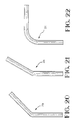
- Figures 20 to 23 show optical mixing rods 22a to 22d, respectively, having arcs of curvature of 30°, 45°, 90°, and 135°, respectively.
- Figure 24 shows a mixing rod 22e having a plurality of arcs of curvature of different value. Such arcs, or the combinations thereof shown in Figure 24 may be selected for mechanical reasons, for example. The uniformity achieved by the use of these mixing rods, has been found to be better than that achieved with the use of a rectilinear mixing rod.
- the mixing rod may be curved in a single plane, as shown, or it may be of spiral, for example, helical, form.
- Figure 25 shows mixing rods 22f of other than circular cross sectional shape, for use in a two fibre-to-two fibre coupling device.
Description
- This invention relates to an optical coupling device for transmitting light emitted by a first optical fibre to each of a plurality of second optical fibres.
- Such a coupling device is disclosed in an article entitled POLYMERIC OPTICAL MIXING ROD COUPLER by L.L. Blyler and G.J. Grimes, of A.T. and T. Bell Laboratories, published in the proceedings of the 39th Electronic Conference, Houston, Texas, 1989, Pages 490 to 493. This known coupling device comprises a rectilinear mixing rod consisting of a Teflon (registered Trade Mark) tube filled with a transparent casting resin. A bundle of optical fibres is received in one end of the tube and a single large fibre is received in the other end thereof. The device may be operated as a light splitter or as a light combiner.
- A further known optical coupling device, which is described in detail below, with reference to Figures 1 to 5 of the accompanying drawings, comprises first and second tubular connectors receiving the first and second optical fibres, respectively, with a cladded, optical end of each fibre exposed at a forward end of the respective connector, and an optical mixing rod interposed between the forward ends of the connectors, the mixing rod having optical ends optically interfaced with the optical ends of the first and second optical fibres, respectively, so as to distribute light emitted by the first optical fibre to illuminate the optical ends of the second optical fibres. The mixing rod of this further known optical coupling device, is rectilinear.
- Such optical coupling devices, which are known as star couplers, are used for example in automotive vehicles, in optical instruments, for industrial automation, or for monitoring sensors in a machine, where it is required that a single light signal be transmitted to a plurality of light sensitive devices.
- It has been found however, as described in greater detail below, that where such a rectilinear mixing rod is used, not all of the second fibres, that is to say the receiving fibres, are illuminated to an equal extent when the first fibre is emissive, so that the illumination of some of the second fibres may be inadequate. This disadvantage occurs, because the optical power transmitted by the mixing rod decreases in a direction away from the longitudinal central axis of the mixing rod.
- Patent specification US 4184740 discloses an optical coupling device in which the mixing rod comprises a curved central portion connecting first and second rectilinear portions of the mixing rod, each of these second portions terminating in a respective one of the optical ends of the mixing rod.
- By virtue of the curvature of the mixing rod, the light proximate to the longitudinal axis of the mixing rod, is constrained by the curvature thereof, so as to be reflected at different angles from the curving of the mixing rod to provide substantially uniform light distribution throughout the cross section of the emitting end of the mixing rod whereby the receiving fibres are substantially equally illuminated. The cross sectional shape of the mixing rod may be circular, or it may be other than circular, for example, in the case of a two fibre-to-two fibre coupling device.
- In the commercial production of optical fibres, the fibres when produced, are reeled for transport to the end user. A disadvantage of an internally smooth-walled connector, is that since the fibres have a plastic memory and thus tend, when de-reeled, to bend so as to return towards their reeled configurations, the longitudinal axes of the fibres do not, if the fibres of a bundle are inserted together into the connector, align themselves with the longitudinal axis of the connector. In order to avoid this disadvantage, which would cause light to be coupled out of the system, thereby causing attenuation of the transmitted light, the current practice is to insert the fibres of a bundle into the connector one by one, or to confine the bundle of fibres by means of an O-ring, tape or tube, to ensure that the fibres extend parallel to the longitudinal axis of the connector when inserted thereinto. A tubular glass optical fibre connection is described in patent specification EP 0436112 into which fibres are fed individually. The internal configuration of the passage into which the fibres are fed holds them correctly juxtaposed until the glass tube is shrunk onto the fibres.
- An object of the invention is to provide an optical coupling device which allows simultaneous insertion of a plurality of fibres of a bundle into the device and overcomes the disadvantages discussed above.
- An optical coupling device according to the invention is defined in
claim 1. - Thus according to the invention, there is provided an optical coupling device of the kind referred to above including a tubular connector formed with a series of internal peripheral, axially extending fibre guiding grooves opening into the forward end of the connector, each groove receiving a respective outer fibre of the bundle, these respective outer fibres retaining at least a central fibre of the bundle firmly into position in parallel relationship with said respective outer fibres. Each groove has a fibre lead-in rear portion tapering in width and depth towards a fibre lead-in mouth opening into the rear end of the connector and tapering forwardly thereof.
- The fibres of the bundle can accordingly be inserted simultaneously into the connector without the disadvantage mentioned above.
- The number of fibres may be seven, the number of grooves being six. In this case, a single fibre is held in alignment with the longitudinal axis of the connector. The bundle of fibres, may however comprise a much greater number fibres, for example thirty two fibres. In this case, the outer fibres of the bundle, will hold a substantial number of inner fibres, in parallel relationship with the longitudinal access of the connector.
- It has been found that where the coupling device comprises two bundles, each of seven fibres, equality of light distribution in the mixing rod is optimum, where the arc of curvature of the curved portion of the mixing rod is 180°, the optimum radius of the curved portion being approximately 45mm, although considerably improved light distribution can be attained where a said arc of curvature is between 30° and 180°. Other values are optimum where the bundles of fibres comprise other numbers of fibres.
- The radius of curvature of the mixing rod, which will depend partly upon mechanical considerations, may be between 20 mm and 50 mm. For a thirteen fibre-to-thirteen fibre coupling device the mixing rod core diameter is preferably 4.52mm and for a nineteen fibre-to-nineteen fibre coupling device said diameter is preferably 5.07 mm. The mixing rod may be of non-circular cross section where, for example, the coupling device is a two fibre-to-two fibre device.
- For a better understanding of the present invention and to show how it may be carried into effect, reference will now be made by way of example to the accompanying drawings in which;
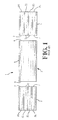
- Figure 1 is a diagrammatic side view of a known optical star coupling device comprising a pair of optical fibre connectors each receiving a bundle of optical fibres, and a rectilinear optical mixing rod;
- Figures 2 and 3 are front end views of respective ones of the connectors illustrating an aspect of the operation of the known coupling device;
- Figure 4 is an end view of the optical mixing rod of the device shown in Figure 1;
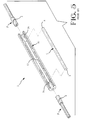
- Figure 5 is an exploded isometric view of a practical example of the known coupling device illustrated diagrammatically in Figures 1 to 4;
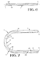
- Figure 6 is an enlarged diagrammatic side view of the mixing rod of the device of Figure 5, illustrating the propagation of light through the mixing rod;
- Figure 7 is an enlarged side view of the optical mixing rod of an optical star coupling device according to a preferred embodiment of the present invention, illustrating the improved propagation of light therethrough;
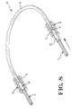
- Figure 8 is an enlarged first isometric view of the coupling device according to said preferred embodiment;
- Figure 9 is an enlarged, diagrammatic, fragmentary, side view of an end portion of the optical mixing rod of the device of Figure 8, illustrating cladding thereon;
- Figure 10 is an end view of Figure 9;
- Figure 11 is an enlarged second isometric view of the coupling device of Figure 8;
- Figure 12 is a front end view of an optical fibre connector of the coupling device of Figures 8 and 11;
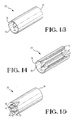
- Figures 13 to 16 are a rear isometric view, a rear isometric view shown partly in longitudinal section, a front isometric view and a front isometric view shown partly in longitudinal section, respectively, of the connector of Figure 12;
- Figure 17 is a front isometric view of the connector of Figures 12 to 16, when receiving a bundle of optical fibres;
- Figure 18 is a front end view of Figure 17;
- Figure 19 is an enlarged isometric view, shown partly in section, illustrating details of Figure 8;
- Figures 20 to 24 are enlarged side views of optical mixing rods according to embodiments other than said preferred embodiment;
- Figure 25 shows end, and isometric views of mixing rods of other than circular cross sectional shape; and
- Figures 26 and 27 are an enlarged isometric view and side view, respectively, illustrating the behaviour of fibres in a bundle of optical fibres to be inserted into a connector therefor.
-
- A known optical
star coupling device 1 for guiding light from a single optical fibre of a plurality thereof, into a plurality of optical fibres will now be described from a theoretical point of view with reference to Figures 1 to 4. Thecoupling device 1 comprises a pair ofoptical fibre connectors optical mixing rod 5 provided withcladding 6. Therod 5 is of circular cross-section according to the present example, and may be described as an optical wave guide. Such a wave guide could, however, be of rectangular cross-section. The polishedoptical ends 7 of the fibres of each bundle butt against, at optical interfaces, and are connected to, the respective flat optical end faces 8 and 9 of themixing rod 5. Eachconnector connector 4 is light emissive, as indicated by hatching, the light from the fibre F5 is guided by themixing rod 5 so as to illuminate the ends of all of the fibres F1 to F7 in theconnector 2, also as indicated by hatching. Alternatively, a selected fibre in theconnector 2 could be made emissive so as to illuminate theends 7 of all the fibres in theconnector 4. Such a coupling device is used for example in an optical control system, for example in a motor vehicle, an optical instrument, for industrial automation, or for monitoring sensors in a machine; where it is required that a single light signal be transmitted to a plurality of light sensitive devices. - As shown in Figure 5, in a practical example of the known optical coupling device, the
connectors housing 10 having acentral bore 12 receiving therod 5, eachconnector respective end portion 14 of thebore 12. - In the commercial production of optical fibres, the fibres when produced, are reeled for transport to the end user. A disadvantage of an internally smooth walled connector, is that since the fibres F1 to F7 have a plastic memory and thus tend, when de-reeled, to bend so as to return towards their reeled configurations, the longitudinal axes of the fibres, do not, if the fibres of a bundle are inserted together into the connector, align themselves with the longitudinal axis of the connector. As shown in Figures 26 and 27, is a bundle of fibres F, the fibres tend to twist from straight positions SP thereof so as to tilt with respect to the longitudinal axis Z-Z of the bundle, so that the longitudinal axis Y-Y of a twisted fibre is displaced from the axis Z-Z by an angle t of tilt, whereby the optical end faces 7 of the fibres are displaced, with respect to the straight positions SP. In order to avoid this disadvantage, which would cause light to be coupled out of the system, thereby causing attenuation of the transmitted light, the current practice is to insert the fibres of a bundle into the connector one by one, or to confine the bundle of fibres by means of an Oring, tape or tube to ensure that the fibres extend parallel to the longitudinal axis of the connector when inserted thereinto.
- Although a typical seven fibre-to-seven fibre coupling device has been described above by way of example, such a coupling device, can comprise a multiplicity of fibres in each bundle.
- In order to ensure that each of the receiving fibres is illuminated to the same extent, the distribution of the light achieved by the mixing rod should, as far as possible, be equal. Uniformity defined as the difference between the highest and the lowest power measured at all the input ports and output ports of the coupling device, should, therefore, be as low as possible.
- In theory the greater is the length of the mixing
rod 5, the lower is the uniformity. It has been found however, that even with the use of a mixing rod which is as long as 100cm the equality of the light distribution is insufficient to ensure adequate illumination of all of the receiving fibres. In therectilinear mixing rod 5 the optical power decreases in a direction away from a longitudinal central axis of the selected light emitting fibre. When, a central fibre F7, for example, of theconnector 4, is emissive, the low order modes LOM that is to say the light beams proximate to the longitudinal axis X-X of therod 5 propagate, as shown in Figure 6, in the direction of the axis X-X, although the high order modes HOM, that is to say the light beams more remote from the axis X-X are reflected by thecladding 6 of therod 5 and are thus better distributed than the low order modes LOM. The power measured at the middle receiving fibre F7 is accordingly substantially the greater, whereas the other receiving fibres F1 to F6, are, consequentially, illuminated to a lesser extent. Said uniformity is also insufficient where one of the fibres F1 to F6 is emissive. - A fibre optic star coupling device according to a preferred embodiment of the present invention will now be described with reference to Figures 7 to 19. As best seen in Figures 8 and 11, an optical
star coupling device 16 for the same purpose as the knowndevice 1, and also, being, by way of example, a seven fibre to seven fibre coupling device, comprises a pair ofhousings 18, a pair ofconnectors 20 receiving a bundle of optical fibres F and anoptical mixing rod 22 of U-shaped configuration. - As best seen in Figure 19, each
housing 18, which is of circular crosssection, has a central axial bore 24 having arear portion 26 of constant cross-section, opening into aconnector receiving face 28 of thehousing 18 and aforward portion 30 of smaller cross-section than therear portion 26, opening into a mixingrod receiving face 32 of thehousing 18. One of theconnectors 20 extends partially into thebore portion 24, with anend face 33 of theconnector 20 in spaced relationship with optical anend face 34 of one end portion of the mixingrod 22 theend face 34 may, as described below, be either the emissive, or the receiving end face of therod 22. The space between thefaces interface 35 between them as shown at the bottom of Figure 8 and at the top of Figure 11. The optimum situation is when the faces 33 and 34 are in contact, that is to say when there is no space between them as shown at the top of Figure 8 and at the bottom of Figure 11. - As best seen in Figures 13 to 16, each
connector 20 which is in the form of an overall circular cross-section hollow tube, has a fibre bundle receivingrear end 36 having an outwardly flared, internally smooth, circular cross-section, frusto-conical fibre lead-inmouth 38. There extend axially of theconnector 20, from itsforward end 33, six parallel, internal, peripheral, fibre guidingaxial grooves 40 which are of smoothly arcuate concave cross-section and are of identical dimensions and configuration matching the fibre diameter. Thegrooves 40 are constantly spaced from each other about the longitudinal axis of theconnector 20 in a circular array and are separated from one another by flat toppedaxial splines 42. Eachgroove 40 has a fibre lead inrear end portion 44 which tapers both in width and in depth toward themouth 38 and terminates at the forward end thereof. A bundle F of seven fibres F1 to F7 can readily be inserted into theconnector 20 from itsfibre receiving end 36, guided by the walls of the frusto-conical mouth 38 so that each of the outer fibres F1 to F6 of the bundle F, guided by theportion 44 of therespective groove 40 is received in the remainder of thegroove 40, with the leading end of each fibre protruding slightly beyond theforward end 33 of theconnector 20. The outer fibres F1 to F6 hold the centre fibre F7 firmly in its position along the central longitudinal axis of theconnector 20, as best seen in Figures 17 and 18. The bundle of fibres F, so inserted into theconnector 20, is bonded into theconnector 20 by means of a bonding material which is preferably index matched with the cladding material of the fibres.. The leading ends of the fibres are then polished flat to provideoptical ends 7 and so as to be level with theforward end 33 of theconnector 20, when the bonding material has cured. The diameter of the core of each fibre is, in the present example, typically 0.98mm, the fibre bundle diameter being 3mm, overall. - The
optical mixing rod 22 may be a large cross-section polycarbonate optical fibre having a cladding 46 (Figures 9 and 10); having refractive indices matched to thefibres 1 to 7. The core of therod 22 may be of pure fused silica, the cladding being fused silica. In any event, provision must be made for light beams to be reflected in thelight rod 22. To this end, the difference in refractive index between the core of therod 22 and the cladding thereof must result in an N.A. (numerical aperture) matching to the fibres F1 to F7 or therod 22 must be coated with a light reflective material, for example, silver or gold, which materials are ideal for the 660nm wavelength range. The N.A. of therod 22 may be between 0.4 and 0.7. Thehousings 18, are also preferably of a low refractive index material, the difference in the refractive index between the housing and the core of therod 22, resulting in an N.A. of 0.50. Alternatively thehousing 18 could have a reflective surface coating over the extent of thebore portion 30. In order to reduce insertion loss and to avoid fresnel losses, a refractive index matching liquid for the 660nm wavelength may be disposed in theinterface 35 between the end faces 33 and 34, although in this case the connectors should be provided with spring loaded adaptors restraining, in known fashion, their withdrawal from the housings. Said matching liquid has the advantage that it is received in the interstices between the fibres, which provide a reservoir allowing for thermal expansion and contraction of the connectors and the housing, the penetration of the matching liquid between the fibres being limited by capillary action. Alternatively, an ultra violet ray curable adhesive resin with the correct refractive index and transmission at 660nm could be substituted for the index matching material, the housing being transparent. For the avoidance of extra transmission losses, the total active diameter of the fibres should be equal to that of the mixing rod, as far as possible, at theinterface 35 between the end faces 33 and 34. - As shown in Figure 7, the mixing
rod 22 is so shaped that the low order modes LOM are forced to propagate other than in the axial direction. The distribution of the high order modes HOM is also improved. These improvements are achieved by virtue of the curvature of the mixingrod 22. The low order modes LOM, propagate from the notional light receiving optical end of therod 22, which end is referenced 34 in Figure 7, in a direction parallel to the central axis of therod 22, along a firstrectilinear portion 48 thereof, up to the centralcurved portion 50 of therod 22, the low order modes LOM being reflected at thejunction 52 between theportions 28 and 50 (at which junction the curvature of therod 22 begins, as seen from the end 46), by thecladding 46 of therod 22. Since, by virtue of said curvature, the angles of incidence of the modes LOM against thecladding 46, change as the modes LOM propagate along thecurved portion 50, the modes LOM are reflected at different angles therealong so as to be well distributed upon reaching the secondrectilinear portion 54 of therod 22, leading to the notional light emitting optical end of therod 22, which end is referenced 56 in Figure 7, of therod 22. The high order modes HOM are similarly reflected in theportion 50 of therod 22 so that their distribution therein is also improved. Uniform light distribution throughout the cross section of the emittingend 56 is thereby achieved, so that the receiving fibres are thereby substantially equally illuminated, by the light emitted by the single light emiting fibre at the receivingend 46 of the mixingrod 22. - The
rod 22, has for example an overall diameter of 3mm, and an arc of curvature of 180° having a radius of 45mm. It has been found that this selection of values produces equality of light distribution, such that the uniformity may amount to unity. In a seven fibre-to-seven fibre coupling device using a rectilinear rod according to the prior art, the uniformity may amount to 7 dB. - The
end 56 of therod 22 will, sometimes, during the use of the coupling device, be the light emitting end of therod 22, theend 34 thereof being the light receiving end. The uniformity of light distribution in therod 22 will in either case be as described above. - For some applications, the bundle of fibres in one of the
connectors 20 may be replaced by a single large fibre tapered towards the interface to present a light receiving/transmitting end of the same diameter as one of the fibres in theother connector 20. The coupling device may thus be operated as a light combiner. - Figures 20 to 23 show optical mixing rods 22a to 22d, respectively, having arcs of curvature of 30°, 45°, 90°, and 135°, respectively.
- Figure 24 shows a mixing rod 22e having a plurality of arcs of curvature of different value. Such arcs, or the combinations thereof shown in Figure 24 may be selected for mechanical reasons, for example. The uniformity achieved by the use of these mixing rods, has been found to be better than that achieved with the use of a rectilinear mixing rod. The mixing rod may be curved in a single plane, as shown, or it may be of spiral, for example, helical, form.
- Figure 25 shows mixing rods 22f of other than circular cross sectional shape, for use in a two fibre-to-two fibre coupling device.
Claims (16)
- An optical coupling device (16) for transmitting light emitted by a first optical fibre (F7) to each of a plurality of second optical fibres (F1 to F7) forming a bundle (F), the coupling device comprising; first and second tubular connectors (20) each having a forwardly tapering fibre lead-in mouth (38) opening into a rear end (36) thereof said connectors (20) receiving said first and second fibres, respectively, with an optical end (7) of each fibre exposed at a forward end (33) of the respective connector (20); and an optical, cladded mixing rod (22) interposed between the forward ends of the connectors, the mixing rod (22) having optical ends (34, 56) optically interfaced with optical ends (7) of the first and second optical fibres, respectively, so as to distribute light emitted by the first optical fibre (F7) to illuminate the optical ends of the second optical fibres (F1 to F7), the mixing rod (22) comprising a curved central portion (50) connecting first and second rectilinear end portions (48, 54) of the mixing rod, each terminating in a respective one of said optical ends (34, 56) of the mixing rod (22),
characterised in that at least the second tubular connector (20) is formed with a series of internal peripheral, axially extending, fibre guiding grooves (40) opening into the forward end (33) of the connector (20), each groove (40) receiving a respective fibre (F1 to F6) of the bundle (F), these respective fibres (F1 to F6) acting together to retain at least a central fibre (F7) of the bundle (F) firmly in position in parallel relationship with respective fibres (F1 and F6) and each groove (40) has a fibre lead-in rear portion (44) tapering in width and in depth towards the fibre lead-in mouth of the associated connector. - A device as claimed in Claim 1 characterised in that the curved portion (50) of the mixing rod (22) is curved through an arc of between 30° and 180°.
- A device as claimed in Claim 1 or 2 characterised in that the curved portion (50) of the mixing rod (22) is curved through an arc of approximately 180°.
- A device as claimed in any preceding claim characterised in that the radius of curvature of the curved portion (50) of the mixing rod (22) is between 20mm and 50mm.
- A device as claimed in any preceding claim, characterised in that the radius of curvature of said curved portion (50) is approximately 45mm, the mixing rod (22) having an overall diameter of approximately 3mm, where each of the connectors (20) receives seven optical fibres (F1 to F7).
- A device as claimed in any one of Claims 1 to 4, characterised in that the mixing rod (22) has a core diameter of approximately 4.52mm, where each connector (20) receives thirteen fibres.
- A device as claimed in any one of Claims 1 to 4 characterised in that the mixing rod (22) has a core diameter of approximately 5.07mm, where each connector (20) receives nineteen fibres.
- A device as claimed in any one of the preceding claims, characterised in that the optical transmission through the mixing rod (22) amounts to at least 99.98% measured on a wavelength of 660nm.
- A device as claimed in any one of the preceding claims, characterised in that the mixing rod (22) is a polycarbonate fibre having a cladding.
- A device as claimed in any one of Claims 1 to 8 characterised in that the mixing rod (22) has a core of pure fused silica and a cladding of fused silica.
- A device as claimed in any one of Claims 1 to 9, characterised in that the mixing rod (22) has a cladding of a light reflective material.
- A device as claimed in any one of the preceding claims, characterised in that the mixing rod (22) has a numerical aperture of between 0.40 and 0.70 matched to the corresponding fibres.
- A device as claimed in any one of the preceding claim, characterised in that the forward end (33) of each connector (20) is received in a tubular housing (18), which also receives a respective optical end (34, 56) of the mixing rod (22) a refractive index matching material being disposed in the interface (35) between said optical ends in the housing (18).
- A device as claimed in Claim 13, characterised in that the refractive index matching material is a liquid or adhesive resin.
- A device as claimed in any preceding claim characterised by a first tubular housing (18) having a first axial rear bore portion (26) receiving the forward end (33) of the first tubular connector (20), and a second tubular housing (18) having a first axial rear bore portion (26) receiving the forward end (33) of the second tubular connector (20), each housing (18) having an axial, forward, second bore portion (30) of smaller cross-sectional area than said first portion (26), communicating with the first bore portion (26) and receiving a respective optical end (34, 56) of the mixing rod (22).
- A device as claimed in claim 15, characterised in that each housing (18) is made of a low refractive index material, the difference in refractive index between the housing (18) and the core of the mixing rod (22) resulting in a numerical aperture of 0.50, or at least being matched to the mixing rod.
Applications Claiming Priority (4)
| Application Number | Priority Date | Filing Date | Title |
|---|---|---|---|
| GB9127369 | 1991-12-24 | ||
| GB9127367 | 1991-12-24 | ||
| GB919127367A GB9127367D0 (en) | 1991-12-24 | 1991-12-24 | Confining optical fibres |
| GB919127369A GB9127369D0 (en) | 1991-12-24 | 1991-12-24 | Optical coupling device |
Publications (3)
| Publication Number | Publication Date |
|---|---|
| EP0549332A2 EP0549332A2 (en) | 1993-06-30 |
| EP0549332A3 EP0549332A3 (en) | 1993-08-18 |
| EP0549332B1 true EP0549332B1 (en) | 1999-03-17 |
Family
ID=26300076
Family Applications (1)
| Application Number | Title | Priority Date | Filing Date |
|---|---|---|---|
| EP92311717A Expired - Lifetime EP0549332B1 (en) | 1991-12-24 | 1992-12-22 | Optical coupling device |
Country Status (4)
| Country | Link |
|---|---|
| US (1) | US5408551A (en) |
| EP (1) | EP0549332B1 (en) |
| JP (1) | JPH05257029A (en) |
| DE (1) | DE69228667T2 (en) |
Families Citing this family (20)
| Publication number | Priority date | Publication date | Assignee | Title |
|---|---|---|---|---|
| US5841921A (en) * | 1997-01-31 | 1998-11-24 | Wallace; Troy B. | Optical coupling device |
| US5807242A (en) * | 1997-03-24 | 1998-09-15 | Synergetics, Inc. | Microsurgical laser probe with homogeneous laser light field |
| DE10021940A1 (en) * | 2000-05-05 | 2001-11-15 | Instr Systems Optische Messtec | Light transmission device with thick-core fiber for measurement of photometric and radiometric variables, uses bracing device coupled to connector for guidance of part-section of thick-core fiber |
| KR20020063577A (en) * | 2000-09-22 | 2002-08-03 | 도꾜도 | Concentration Measurer |
| AU2002337086A1 (en) * | 2001-09-12 | 2003-03-24 | Tecan Trading Ag | Optical device, system and use thereof |
| JP3922085B2 (en) * | 2002-04-25 | 2007-05-30 | ヤマハ株式会社 | Optical fiber bundle holding structure |
| DE10237202A1 (en) * | 2002-08-14 | 2004-02-26 | Carl Zeiss Jena Gmbh | Optical integrator bar for optical projectors, uses a number of luminescent diodes that introduce light that is reflected of internal surfaces to form a homogeneous output |
| KR100510673B1 (en) * | 2003-03-03 | 2005-08-31 | 엘지전자 주식회사 | Laser Display |
| DE10314289A1 (en) * | 2003-03-29 | 2004-10-07 | Schölly Fiberoptic GmbH | image conductor |
| US7561769B2 (en) | 2004-03-16 | 2009-07-14 | Sumitomo Electric Industries, Ltd. | Optical fiber for irradiation-light transfer and light irradiation device equipped with the same |
| DE102005010344B4 (en) * | 2005-03-07 | 2007-05-31 | CCS Technology, Inc., Wilmington | Device for bending an optical waveguide and arrangement for attenuating light in an optical waveguide |
| WO2009148795A2 (en) * | 2008-05-30 | 2009-12-10 | 3M Innovative Properties Company | Flexible optical coupling |
| US8488937B2 (en) * | 2009-08-06 | 2013-07-16 | Tyco Electronics Canada, Ulc | Light distribution assembly |
| JP5771977B2 (en) * | 2010-12-22 | 2015-09-02 | コニカミノルタ株式会社 | Fiber optic ferrule |
| EP2579075A1 (en) | 2011-10-06 | 2013-04-10 | Ivoclar Vivadent AG | Rod-shaped light-guide |
| US11300730B2 (en) * | 2013-07-30 | 2022-04-12 | The Boeing Company | Plastic and glass optical fiber bus network having plural line replaceable units transmitting to a mixing rod |
| US10564357B2 (en) | 2013-07-30 | 2020-02-18 | The Boeing Company | Plastic optical fiber bus network using tapered mixing rods |
| US9322987B2 (en) * | 2013-08-27 | 2016-04-26 | International Business Machines Corporation | Multicore fiber coupler between multicore fibers and optical waveguides |
| US9778419B1 (en) | 2016-06-23 | 2017-10-03 | The Boeing Company | Fiber optical system with fiber end face area relationships |
| US10263706B2 (en) * | 2017-04-18 | 2019-04-16 | The Boeing Company | Single-fiber bidirectional controller area network bus |
Family Cites Families (11)
| Publication number | Priority date | Publication date | Assignee | Title |
|---|---|---|---|---|
| US3969016A (en) * | 1975-05-09 | 1976-07-13 | Bell Telephone Laboratories, Incorporated | Low dispersion optical fiber wave guiding structures with periodically deformed waveguide axis |
| FR2331802A1 (en) * | 1975-11-14 | 1977-06-10 | Thomson Csf | OPTICAL COUPLING DEVICE FOR INTERCONNECTION OF LIGHT GUIDES IN AN OPTICAL TRANSMISSION SYSTEM, AND CORRESPONDING TRANSMISSION SYSTEM |
| US4125315A (en) * | 1976-07-28 | 1978-11-14 | Vivitar Corporation | Light mixing device |
| FR2366588A1 (en) * | 1976-10-01 | 1978-04-28 | Thomson Csf | MULTI-CHANNEL COUPLER FOR OPTICAL FIBER LINK |
| FR2372442A1 (en) * | 1976-11-30 | 1978-06-23 | Thomson Csf | COUPLING DEVICE FOR INTERCONNECTION OF OPTICAL WAVEGUIDES AND OPTICAL TRANSMISSION SYSTEM INCLUDING SUCH A DEVICE |
| US4676594A (en) * | 1984-11-16 | 1987-06-30 | American Telephone And Telegraph Company | Optical fiber mode scrambler |
| EP0347233A3 (en) * | 1988-06-16 | 1991-02-13 | Gec-Marconi Limited | Integrated optic devices |
| US5058979A (en) * | 1989-06-22 | 1991-10-22 | Fujikura Ltd. | Optical fiber coupler and a fabrication method for the same |
| US4995692A (en) * | 1990-02-06 | 1991-02-26 | General Motors Corporation | Fiber optic star coupler |
| US5018814A (en) * | 1990-02-13 | 1991-05-28 | Physical Optics Corporation | Broadband single-mode optical coupler |
| US5054874A (en) * | 1990-12-17 | 1991-10-08 | Her Majesty The Queen In Right Of Canada, As Represented By The Minister Of Communications | Coupler fabrication techniques for dissimilar fibers |
-
1992
- 1992-12-22 DE DE69228667T patent/DE69228667T2/en not_active Expired - Fee Related
- 1992-12-22 EP EP92311717A patent/EP0549332B1/en not_active Expired - Lifetime
- 1992-12-24 JP JP4357554A patent/JPH05257029A/en active Pending
-
1993
- 1993-11-22 US US08/156,521 patent/US5408551A/en not_active Expired - Fee Related
Also Published As
| Publication number | Publication date |
|---|---|
| DE69228667T2 (en) | 1999-09-30 |
| EP0549332A2 (en) | 1993-06-30 |
| US5408551A (en) | 1995-04-18 |
| EP0549332A3 (en) | 1993-08-18 |
| JPH05257029A (en) | 1993-10-08 |
| DE69228667D1 (en) | 1999-04-22 |
Similar Documents
| Publication | Publication Date | Title |
|---|---|---|
| EP0549332B1 (en) | Optical coupling device | |
| US3950075A (en) | Light source for optical waveguide bundle | |
| US3995935A (en) | Optical coupler | |
| US3832028A (en) | Coupler for optical waveguide light source | |
| US5757994A (en) | Three-part optical coupler | |
| US4705352A (en) | Fiber optic connector | |
| US4400054A (en) | Passive optical coupler | |
| US4836637A (en) | Expanded-beam fiber-optic connector | |
| EP0307487B1 (en) | Collimator lens for optical fiber | |
| EP0080887A2 (en) | Fiber optics communications modules | |
| EP0361498A2 (en) | An apparatus for optically connecting a single-mode optical fiber to a multi-mode optical fiber | |
| KR940002621A (en) | Fiber optic coupler and method of manufacturing the same | |
| CA2056925A1 (en) | Optical fiber amplifier and coupler | |
| US20060165358A1 (en) | Compact bundles of light guides with sections having reduced interstitial area | |
| US5666448A (en) | Variable splitting optical coupler | |
| EP1979772B1 (en) | Sleeved optical fiber for reduced lateral loss and method for making the same | |
| US4530566A (en) | Optical fiber duplex coupler | |
| US4722582A (en) | Optical-fibre coupler | |
| GB2094995A (en) | Optical distributors using optical fibres | |
| US5071217A (en) | Precision focusing and locating collar for a fiber optic connector | |
| US4995692A (en) | Fiber optic star coupler | |
| US4718746A (en) | Optical fiber graded index connector | |
| EP0184432A2 (en) | Optical coupler | |
| CN113050223A (en) | Polymer waveguide connector, manufacturing method thereof and connector set | |
| US6798949B2 (en) | Optical assembly with integrated lens protrusion |
Legal Events
| Date | Code | Title | Description |
|---|---|---|---|
| PUAI | Public reference made under article 153(3) epc to a published international application that has entered the european phase |
Free format text: ORIGINAL CODE: 0009012 |
|
| PUAL | Search report despatched |
Free format text: ORIGINAL CODE: 0009013 |
|
| AK | Designated contracting states |
Kind code of ref document: A2 Designated state(s): DE ES FR GB IT NL SE |
|
| AK | Designated contracting states |
Kind code of ref document: A3 Designated state(s): DE ES FR GB IT NL SE |
|
| 17P | Request for examination filed |
Effective date: 19940122 |
|
| 17Q | First examination report despatched |
Effective date: 19950808 |
|
| GRAG | Despatch of communication of intention to grant |
Free format text: ORIGINAL CODE: EPIDOS AGRA |
|
| GRAG | Despatch of communication of intention to grant |
Free format text: ORIGINAL CODE: EPIDOS AGRA |
|
| GRAH | Despatch of communication of intention to grant a patent |
Free format text: ORIGINAL CODE: EPIDOS IGRA |
|
| GRAH | Despatch of communication of intention to grant a patent |
Free format text: ORIGINAL CODE: EPIDOS IGRA |
|
| RBV | Designated contracting states (corrected) |
Designated state(s): DE FR GB |
|
| GRAA | (expected) grant |
Free format text: ORIGINAL CODE: 0009210 |
|
| AK | Designated contracting states |
Kind code of ref document: B1 Designated state(s): DE FR GB |
|
| REF | Corresponds to: |
Ref document number: 69228667 Country of ref document: DE Date of ref document: 19990422 |
|
| ET | Fr: translation filed | ||
| PLBE | No opposition filed within time limit |
Free format text: ORIGINAL CODE: 0009261 |
|
| STAA | Information on the status of an ep patent application or granted ep patent |
Free format text: STATUS: NO OPPOSITION FILED WITHIN TIME LIMIT |
|
| 26N | No opposition filed | ||
| REG | Reference to a national code |
Ref country code: GB Ref legal event code: IF02 |
|
| PGFP | Annual fee paid to national office [announced via postgrant information from national office to epo] |
Ref country code: GB Payment date: 20031105 Year of fee payment: 12 |
|
| PGFP | Annual fee paid to national office [announced via postgrant information from national office to epo] |
Ref country code: FR Payment date: 20031201 Year of fee payment: 12 |
|
| PGFP | Annual fee paid to national office [announced via postgrant information from national office to epo] |
Ref country code: DE Payment date: 20031230 Year of fee payment: 12 |
|
| PG25 | Lapsed in a contracting state [announced via postgrant information from national office to epo] |
Ref country code: GB Free format text: LAPSE BECAUSE OF NON-PAYMENT OF DUE FEES Effective date: 20041222 |
|
| PG25 | Lapsed in a contracting state [announced via postgrant information from national office to epo] |
Ref country code: DE Free format text: LAPSE BECAUSE OF NON-PAYMENT OF DUE FEES Effective date: 20050701 |
|
| GBPC | Gb: european patent ceased through non-payment of renewal fee |
Effective date: 20041222 |
|
| PG25 | Lapsed in a contracting state [announced via postgrant information from national office to epo] |
Ref country code: FR Free format text: LAPSE BECAUSE OF NON-PAYMENT OF DUE FEES Effective date: 20050831 |
|
| REG | Reference to a national code |
Ref country code: FR Ref legal event code: ST |