JP5771977B2 - Fiber optic ferrule - Google Patents
Fiber optic ferrule Download PDFInfo
- Publication number
- JP5771977B2 JP5771977B2 JP2010285352A JP2010285352A JP5771977B2 JP 5771977 B2 JP5771977 B2 JP 5771977B2 JP 2010285352 A JP2010285352 A JP 2010285352A JP 2010285352 A JP2010285352 A JP 2010285352A JP 5771977 B2 JP5771977 B2 JP 5771977B2
- Authority
- JP
- Japan
- Prior art keywords
- optical fiber
- holding groove
- fiber ferrule
- ferrule
- optical
- Prior art date
- Legal status (The legal status is an assumption and is not a legal conclusion. Google has not performed a legal analysis and makes no representation as to the accuracy of the status listed.)
- Expired - Fee Related
Links
Images


Description
本発明は、複数本の光ファイバを保持する光ファイバフェルールに関する。 The present invention relates to an optical fiber ferrule that holds a plurality of optical fibers.
光ファイバフェルールは、光通信用途をはじめとした多くの分野で広く利用されている。この光ファイバフェルールを構成するにあたっては、まず一つとして光ファイバを高精度に保持できることが求められる。
光ファイバの高精度保持は、従来から追及されてきた課題である。また光ファイバの保持状態を維持すること、光ファイバフェルールを小型化することも同様に従来から追求されてきた。
それとともに、加工のし易さ、組立の容易さも求められる。そして近年では、固定用接着剤の収縮による影響も考慮されている。
Optical fiber ferrules are widely used in many fields including optical communication applications. In configuring this optical fiber ferrule, first, it is required that the optical fiber can be held with high accuracy.
Maintaining high-precision optical fibers is a problem that has been pursued in the past. In addition, maintaining the holding state of the optical fiber and reducing the size of the optical fiber ferrule have been pursued in the same manner.
At the same time, ease of processing and ease of assembly are also required. In recent years, the influence of shrinkage of the fixing adhesive is also considered.
光ファイバフェルールの小型化を追求するため、一つの挿通孔に複数本の光ファイバを保持する光ファイバフェルールを考える。
特許文献1〜4には、一つの円形孔に複数本の光ファイバを挿通して保持する光ファイバフェルールが記載されている。
特許文献2〜5には、複数の円形孔にそれぞれ1本の光ファイバを挿通して保持する光ファイバフェルールであって、その複数の円形孔が繋がっているものが記載されている。
また特許文献2〜4には、両端が半円形の長孔状断面を有した孔にそれぞれ複数本の光ファイバを挿通して保持する光ファイバフェルールであって、その半円形の端部に光ファイバの外周部が沿って挿通されているものが記載されている。
また特許文献3には、挿入部材を光ファイバとともに光ファイバフェルール内に挿入して光ファイバを固定することが提案されている。
In order to pursue miniaturization of the optical fiber ferrule, consider an optical fiber ferrule that holds a plurality of optical fibers in one insertion hole.
Patent Document 3 proposes that an optical fiber is fixed by inserting an insertion member into an optical fiber ferrule together with the optical fiber.
しかし、以上の従来技術にあってもさらに次のような問題があった。
一つの円形孔に複数本の光ファイバを挿通して保持する従来の光ファイバフェルールにあっては、光ファイバフェルールに光ファイバを挿通して内部に固定する組立時に、光ファイバの位置を決めにくく、組立後に、光ファイバの位置が変化するおそれがあり、高精度保持性に問題がある。
複数の円形孔が繋がっている従来の光ファイバフェルールにあっては、挿通孔を精度良く形成することが難しく、大量生産には不向きであるとともに、光ファイバが自身の中心回りに回動するおそれがある。
両端が半円形の長孔状断面を有した挿通孔を持つ従来の光ファイバフェルールにあっては、光ファイバが自身の中心回りに回動するおそれがあるとともに、挿通孔と光ファイバとの隙間に充填される接着剤が、光ファイバの片側に多く偏り、接着剤の収縮による光ファイバの偏った変形が懸念される。
挿入部材が光ファイバとともに挿入される従来の光ファイバフェルールにあっては、挿入部材を製造しなければならないため、部品増、製造コストアップが避けられず、光ファイバを固定できる程度に挿入部材を挿入するから、挿入部材の挿入時に光ファイバを局所的に変形させたり破損させたりするおそれがあり、組立作業性も良好でない。
However, the above-described conventional technology has the following problems.
In a conventional optical fiber ferrule in which a plurality of optical fibers are inserted and held in one circular hole, it is difficult to determine the position of the optical fiber during assembly by inserting the optical fiber through the optical fiber ferrule and fixing it inside. After assembly, the position of the optical fiber may change, and there is a problem in high-precision retention.
In a conventional optical fiber ferrule in which a plurality of circular holes are connected, it is difficult to form an insertion hole with high accuracy, which is not suitable for mass production, and the optical fiber may rotate around its own center. There is.
In a conventional optical fiber ferrule having an insertion hole with a semicircular oblong cross section at both ends, there is a possibility that the optical fiber may rotate around its center, and the gap between the insertion hole and the optical fiber There is a concern that the adhesive filled in is heavily biased to one side of the optical fiber, and the optical fiber is deformed unevenly due to shrinkage of the adhesive.
In the conventional optical fiber ferrule in which the insertion member is inserted together with the optical fiber, the insertion member must be manufactured. Therefore, an increase in parts and a manufacturing cost are unavoidable, and the insertion member is fixed to the extent that the optical fiber can be fixed. Since the optical fiber is inserted, the optical fiber may be locally deformed or damaged when the insertion member is inserted, and the assembly workability is not good.
複数本の光ファイバの位置が軸方向について不均一に変化すると、光ファイバにねじれが生じる。また、光ファイバが自身の中心回りに回動する角度が軸方向について不均一であると、光ファイバにねじれが生じる。
このようなねじれや、接着剤の収縮による偏った変形、挿入部材からの加圧による局所的な変形などにより、光ファイバのコアに応力が残留すると、その光学的特性に影響を与えるおそれがあり、製品の品質管理が煩雑化する。
When the positions of the plurality of optical fibers change non-uniformly in the axial direction, the optical fiber is twisted. Further, when the angle at which the optical fiber rotates about its center is not uniform in the axial direction, the optical fiber is twisted.
If stress remains in the core of the optical fiber due to such twisting, uneven deformation due to shrinkage of the adhesive, or local deformation due to pressurization from the insertion member, its optical characteristics may be affected. Product quality control becomes complicated.
本発明は以上の従来技術における問題に鑑みてなされたものであって、一つの挿通孔に複数本の光ファイバを保持する光ファイバフェルールにおいて、可及的に小径化を図りつつ、製造性良好に複数本の光ファイバを良好な状態で精度良く保持することを課題とする。 The present invention has been made in view of the problems in the prior art described above, and in an optical fiber ferrule that holds a plurality of optical fibers in one insertion hole, while reducing the diameter as much as possible, the productivity is good. It is another object of the present invention to hold a plurality of optical fibers in good condition with high accuracy.
以上の課題を解決するための請求項1記載の発明は、一つの挿通孔に複数本の光ファイバを保持する光ファイバフェルールにおいて、
前記複数本の光ファイバには、互いに外径の異なる光ファイバが含まれ、前記挿通孔内において前記複数本の光ファイバの外周部同士を当接させて保持し、
前記挿通孔の内面に、軸方向に沿って形成され、1本の光ファイバの外周部を落とし込んで保持する保持溝が前記複数本の光ファイバのうち少なくとも1本の光ファイバに対応して形成されてなり、
1本の光ファイバの外周部を落とし込んで保持する前記保持溝は、当該1本の光ファイバに対して1本で構成され、
前記保持溝の内面が円筒状内面により形成され、当該円筒状内面の中心角が180度未満とされてなる光ファイバフェルールである。
The invention according to
The plurality of optical fibers include optical fibers having different outer diameters, and the outer peripheral portions of the plurality of optical fibers are held in contact with each other in the insertion hole,
A holding groove is formed on the inner surface of the insertion hole along the axial direction so as to drop and hold the outer peripheral portion of one optical fiber corresponding to at least one of the plurality of optical fibers. Being
The holding groove for holding the outer peripheral portion of one optical fiber by dropping is constituted by one for the one optical fiber,
In the optical fiber ferrule, the inner surface of the holding groove is formed by a cylindrical inner surface, and the central angle of the cylindrical inner surface is less than 180 degrees.
請求項2記載の発明は、前記複数本の光ファイバの1本毎に対応して前記保持溝が形成されてなる請求項1に記載の光ファイバフェルールである。 A second aspect of the present invention is the optical fiber ferrule according to the first aspect, wherein the holding groove is formed corresponding to each of the plurality of optical fibers.
請求項3記載の発明は、前記複数本の光ファイバのうち一部の光ファイバに対応して前記保持溝が形成されてなる請求項1に記載の光ファイバフェルールである。 A third aspect of the present invention is the optical fiber ferrule according to the first aspect, wherein the holding groove is formed corresponding to a part of the plurality of optical fibers.
本発明によれば、一つの挿通孔内に複数本の光ファイバが互いに当接した状態で収められ、少なくとも1本の光ファイバが保持溝に落とし込まれて保持されるので、可及的に小径化を図りつつ、製造性良好に複数本の光ファイバを良好な状態で精度良く保持するという効果がある。 According to the present invention, a plurality of optical fibers are accommodated in one insertion hole in contact with each other, and at least one optical fiber is dropped and held in the holding groove. There is an effect that a plurality of optical fibers can be held in a good state with good accuracy while reducing the diameter.
以下に本発明の一実施形態につき図面を参照して説明する。以下は本発明の一実施形態であって本発明を限定するものではない。 An embodiment of the present invention will be described below with reference to the drawings. The following is one embodiment of the present invention and does not limit the present invention.
〔第1実施形態〕
まず、本発明の第1実施形態につき、図1及び図2を参照して説明する。
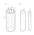
図1(a)に示すように本実施形態の光ファイバフェルール10は、一つの挿通孔11を有する。挿通孔11に図1(b)に示す2本の光ファイバ1,2が挿入されて保持される。図2に示すように光ファイバ1,2が挿通孔11に挿入されて保持される。すなわち、挿通孔11内において光ファイバ1及び光ファイバ2は、その外周部同士を当接させて保持される。また、図1(a)に示すように、挿通孔11の内面に、軸方向に沿って保持溝12a及び保持溝12bが形成されている。一方の光ファイバ1は、その外周部の一部が保持溝12aに落とし込まれ、その反対側の外周部が他方の光ファイバ2に当接することで保持される。他方の光ファイバ2は、その外周部の一部が保持溝12bに落とし込まれ、その反対側の外周部が前記一方の光ファイバ1に当接することで保持される。
[First Embodiment]
First, a first embodiment of the present invention will be described with reference to FIG. 1 and FIG.
As shown in FIG. 1 (a), the
図2(a)に示すように挿通孔11は、断面円形の基本孔11aの内周面に窪みが設けられて保持溝12a,12bが形成されてなる。
保持溝12a,12bは、基本孔11aと平行な軸を有した円筒状内面で形成されている。保持溝12a,12bの半径は、基本孔11aの半径より小さい。保持溝12aは、一方の光ファイバ1の外径と略同一の直径を有し中心角60度〜120度程度の円筒状内面で形成されている。保持溝12bは、他方の光ファイバ2の外径と略同一の直径を有し中心角60度〜120度程度の円筒状内面で形成されている。
保持溝12aと保持溝12bとは、対向する位置に形成されている。
そして、保持溝12aの底点と保持溝12bの底点とを結ぶ線分L0が、基本孔11aの中心Oを通り、光ファイバ1の外径と光ファイバ2の外径との合計が線分L0の長さに略等しくされることによって、本光ファイバフェルール10は、光ファイバ1,2をガタツキ無く精度良く保持することができる。
光ファイバ1、2が保持溝12a,12bから離脱しないように、光ファイバ1の外径と光ファイバ2の外径との合計が、線分L0の長さから保持溝12a,12bのうち浅い方(同じ深さの場合はどちらでも良い)の保持溝の深さを引いた寸法より大きくされる。
As shown in FIG. 2 (a), the
The holding
The holding
A line segment L0 connecting the bottom point of the holding
The total of the outer diameter of the
光ファイバ1が保持溝12aに落とし込まれて保持され、光ファイバ2が保持溝12bに落とし込まれて保持されているので、光ファイバ1も光ファイバ2も、その位置が変化することは防がれる。
また、一方の光ファイバ1は、相対する外周部の一部が保持溝12aと他方の光ファイバ2の外周部に当接して保持されているので、寸法選択と光ファイバ1,2の弾性によって当接部分に集中的に保持圧を得ることができ、光ファイバ1が自身の中心回りに回動することも防ぐことができる。
Since the
Also, since one of the
光ファイバフェルール10の挿通孔11に光ファイバ1及び光ファイバ2を挿入して図2に示す状態を得、挿通孔11に残る空間に接着剤を充填し硬化させることによって、光ファイバ1及び光ファイバ2を光ファイバフェルール10に固定する。
適用する接着剤の性質により、接着剤は、光ファイバ1と保持溝12aとの隙間、光ファイバ2と保持溝12bとの隙間にも侵入する。これらの隙間に侵入する接着剤の量に比較して多量の接着剤が基本孔11a内に充填される。適用する接着剤としては、硬化収縮の少ないものや硬化後に適度に変形するものなど、硬化時や硬化後に光ファイバ1,2に力学的負荷をできるだけ与えないものが好ましい。接着剤から力学的負荷が避けられない場合にあっても、保持溝12a,12bの中心角が180度より小さく、保持溝12a,12bの中心角をより小さくすることによって、光ファイバ1,2の片側に多くの接着剤が偏ることが防がれ、光ファイバの偏った変形が抑制される。
The
Depending on the nature of the adhesive to be applied, the adhesive also enters the gap between the
光ファイバフェルール10の材料及び製法としては、従来技術を適用して実施できる。例えば、光ファイバフェルール10は、ジルコニア粉末等のセラミック原料の粉末をプレス金型によって挿通孔11を含む形状に成形し、焼成することによって製造する。
The material and manufacturing method of the
〔第2実施形態〕
次に、本発明の第2実施形態につき、図3を参照して説明する。本実施形態は上記第1実施形態に対して保持溝12a,12bの配置が変更されている点で異なり、その他は同様である。
[Second Embodiment]
Next, a second embodiment of the present invention will be described with reference to FIG. This embodiment is different from the first embodiment in that the arrangement of the holding
上記第1実施形態における保持溝12aと保持溝12bとは、基本孔11aの中心O周りに180度異なる位置に形成されている。
本実施形態の光ファイバフェルール20にあっては、これと異なり、保持溝12aの円筒状内面の中心Aと、保持溝12bの円筒状内面の中心Bとを結ぶ直線は、基本孔11aの中心Oを通らない。
The holding
In the
角AOBを選択することによって、中心Oに対する光ファイバ1,2の配置を選択することができる。
By selecting the angle AOB, the arrangement of the
〔第3及び第4実施形態〕
次に、本発明の第3及び第4実施形態につき、図4を参照して説明する。第3実施形態の光ファイバフェルール10Aは上記第1実施形態に対して基本孔11aの径が変更されている点で異なり、その他は上記第1実施形態と同様である。第4実施形態の光ファイバフェルール20Aは上記第2実施形態に対して基本孔11aの径が変更されている点で異なり、その他は上記第2実施形態と同様である。
[Third and fourth embodiments]
Next, third and fourth embodiments of the present invention will be described with reference to FIG. The
図4(a)に示すように第3実施形態の光ファイバフェルール10Aにおける基本孔11aの径は、上記第1実施形態のそれに対して小さくされている。例えば、上記第1実施形態にあっては、光ファイバ1の外径をφ1.0(mm)、光ファイバ2の外径をφ2.0(mm)とし、基本孔11aの径を2.8(mm)とする(図面上この比率で描いている)のに対して、第3実施形態の光ファイバフェルール10Aにあっては、光ファイバ1,2の外径を変更せず、基本孔11aの径を2.4(mm)とする(図面上この比率で描いている)。なお、基本孔11aの径が小さくなったことに伴い、保持溝12a,12bの深さがそれぞれ深くされる。それでも、保持溝12a,12bの円筒状内面の中心角を180度未満とする。
As shown in FIG. 4A, the diameter of the
同様に、第4実施形態の光ファイバフェルール20Aにおける基本孔11aの径は、上記第2実施形態のそれに対して小さくされている。例えば、上記第2実施形態にあっては、光ファイバ1の外径をφ1.0(mm)、光ファイバ2の外径をφ2.0(mm)とし、基本孔11aの径を2.8(mm)とする(図面上この比率で描いている)のに対して、第4実施形態の光ファイバフェルール20Aにあっては、光ファイバ1,2の外径を変更せず、基本孔11aの径を2.4(mm)とする(図面上この比率で描いている)。なお、基本孔11aの径が小さくなったことに伴い、保持溝12a,12bの深さがそれぞれ深くされる。それでも、保持溝12a,12bの円筒状内面の中心角を180度未満とする。
Similarly, the diameter of the
光ファイバ1,2の外径の合計に対して、基本孔11aの径を選択することができ、またそれによって、光ファイバフェルールの周壁部の厚みを選択することができ、設計の自由度がある。
The diameter of the
〔第5及び第6実施形態〕
次に、本発明の第5及び第6実施形態につき、図5を参照して説明する。第5実施形態の光ファイバフェルール10Bは上記第1実施形態に対して適用する光ファイバ1,2の外径の組合せが変更されている点で異なり、その他は上記第1実施形態と同様である。第5実施形態の光ファイバフェルール20Bは上記第2実施形態に対して適用する光ファイバ1,2の外径の組合せが変更されている点で異なり、その他は上記第2実施形態と同様である。
[Fifth and sixth embodiments]
Next, fifth and sixth embodiments of the present invention will be described with reference to FIG. The
図5(a)に示すように第5実施形態の光ファイバフェルール10Bが保持する光ファイバ1の外径は、上記第1実施形態のそれに対して大きく、第5実施形態の光ファイバフェルール10Bが保持する光ファイバ2の外径は、上記第1実施形態のそれに対して小さくされている。但し、光ファイバ1,2の外径の合計は不変である。
例えば、上記第1実施形態にあっては、光ファイバ1の外径をφ1.0(mm)、光ファイバ2の外径をφ2.0(mm)とし、基本孔11aの径を2.8(mm)とする(図面上この比率で描いている)のに対して、第5実施形態の光ファイバフェルール10Bにあっては、光ファイバ1の外径をφ1.2(mm)、光ファイバ2の外径をφ1.8(mm)とし、基本孔11aの径を2.8(mm)とする(図面上この比率で描いている)。
光ファイバ1,2の外径変更に対応して、保持溝12a,12bの円筒状内面の半径も変更されている。
As shown in FIG. 5A, the outer diameter of the
For example, in the first embodiment, the outer diameter of the
Corresponding to the outer diameter change of the
同様に、図5(b)に示すように第6実施形態の光ファイバフェルール20Bが保持する光ファイバ1の外径は、上記第2実施形態のそれに対して大きく、第6実施形態の光ファイバフェルール10Bが保持する光ファイバ2の外径は、上記第2実施形態のそれに対して小さくされている。但し、光ファイバ1,2の外径の合計は不変である。
例えば、上記第2実施形態にあっては、光ファイバ1の外径をφ1.0(mm)、光ファイバ2の外径をφ2.0(mm)とし、基本孔11aの径を2.8(mm)とする(図面上この比率で描いている)のに対して、第6実施形態の光ファイバフェルール10Bにあっては、光ファイバ1の外径をφ1.2(mm)、光ファイバ2の外径をφ1.8(mm)とし、基本孔11aの径を2.8(mm)とする(図面上この比率で描いている)。
光ファイバ1,2の外径変更に対応して、保持溝12a,12bの円筒状内面の半径も変更されている。
Similarly, as shown in FIG. 5B, the outer diameter of the
For example, in the second embodiment, the outer diameter of the
Corresponding to the outer diameter change of the
以上のように光ファイバ1,2の外径の組合せは任意であり、同径のものでも、異なる径の如何なる組合せも選択できる。
As described above, the combinations of the outer diameters of the
〔第7、第8、第9及び第10実施形態〕
次に、本発明の第7、第8、第9及び第10実施形態につき、図6を参照して説明する。
図6(a)に示す第7実施形態の光ファイバフェルール30は上記第1実施形態に対して光ファイバ2に対応する保持溝を省略した形態である点で異なり、その他は上記第1実施形態と同様である。
図6(b)に示す第8実施形態の光ファイバフェルール30Zは上記第2実施形態に対して光ファイバ2に対応する保持溝を省略した形態である点で異なり、その他は上記第2実施形態と同様である。
図6(c)に示す第9実施形態の光ファイバフェルール40は上記第1実施形態に対して光ファイバ1に対応する保持溝を省略した形態である点で異なり、その他は上記第1実施形態と同様である。
図6(d)に示す第10実施形態の光ファイバフェルール40Zは上記第2実施形態に対して光ファイバ1に対応する保持溝を省略した形態である点で異なり、その他は上記第2実施形態と同様である。
[Seventh, eighth, ninth and tenth embodiments]
Next, seventh, eighth, ninth and tenth embodiments of the present invention will be described with reference to FIG.
The
The optical fiber ferrule 30Z of the eighth embodiment shown in FIG. 6B is different from the second embodiment in that the holding groove corresponding to the
The
The optical fiber ferrule 40Z of the tenth embodiment shown in FIG. 6 (d) is different from the second embodiment in that the holding groove corresponding to the
上記第1〜第6実施形態においては、複数本の光ファイバの1本毎に対応して保持溝が形成された。
第7実施形態の光ファイバフェルール30にあっては、一方の光ファイバ1を落とし込んで保持する保持溝12cのみ形成されており、他方の光ファイバ2に対応する保持溝は形成されていない。それでも、中心Aと中心Oとを結ぶ直線上に位置する最大隙間寸法L1と光ファイバ2の直径とを合わせることによって、光ファイバ1及び光ファイバ2を保持することができる。
これに対し、第8実施形態の光ファイバフェルール30Zのように、中心Aと中心Oとを結ぶ直線上に位置する最大隙間寸法L2が、光ファイバ2の直径より大きいと、中心A,O,Bが一直線上にない配置を構成できるが、光ファイバ2が移動するおそれがあるため、位置精度の点では、第7実施形態が好ましい。
なお、第7及び第8実施形態にあっては、光ファイバ1が保持溝12cから離脱しないように、光ファイバ1の外径と光ファイバ2の外径との合計が、基本孔11aの径より大きくされる。
In the first to sixth embodiments, the holding groove is formed corresponding to each of the plurality of optical fibers.
In the
On the other hand, when the maximum gap dimension L2 located on the straight line connecting the center A and the center O is larger than the diameter of the
In the seventh and eighth embodiments, the total of the outer diameter of the
第9実施形態の光ファイバフェルール40にあっては、一方の光ファイバ1に対応する保持溝は形成されておらず、他方の光ファイバ2を落とし込んで保持する保持溝12dのみ形成されている。それでも、中心Bと中心Oとを結ぶ直線上に位置する最大隙間寸法L3と光ファイバ1の直径とを合わせることによって、光ファイバ1及び光ファイバ2を保持することができる。
これに対し、第10実施形態の光ファイバフェルール40Zのように、中心Bと中心Oとを結ぶ直線上に位置する最大隙間寸法L4が、光ファイバ1の直径より大きいと、中心A,O,Bが一直線上にない配置を構成できるが、光ファイバ1が移動するおそれがあるため、位置精度の点では、第9実施形態が好ましい。
なお、第9及び第10実施形態にあっては、光ファイバ1が保持溝12dから離脱しないように、光ファイバ1の外径と光ファイバ2の外径との合計が、基本孔11aの径より大きくされる。
In the
On the other hand, when the maximum gap dimension L4 located on the straight line connecting the center B and the center O is larger than the diameter of the
In the ninth and tenth embodiments, the total of the outer diameter of the
以上のように複数本の光ファイバのうち一部の光ファイバに対応して保持溝が形成された形態も有効である。なお、一つの挿通孔に挿通する光ファイバの本数は2以上の任意の本数である。3本の光ファイバを一つの挿通孔に挿通する場合においても、光ファイバの1本毎に対応して保持溝が形成されていてもよいし、一部の光ファイバに対応して保持溝が形成されていてもよい。また、一つの光ファイバフェルールに2以上の挿通孔を設けてよいことも勿論である。 As described above, a configuration in which holding grooves are formed corresponding to some of the plurality of optical fibers is also effective. Note that the number of optical fibers inserted into one insertion hole is an arbitrary number of 2 or more. Even when three optical fibers are inserted into one insertion hole, a holding groove may be formed corresponding to each of the optical fibers, or a holding groove may be formed corresponding to a part of the optical fibers. It may be formed. Of course, two or more insertion holes may be provided in one optical fiber ferrule.
〔第11〜第17実施形態〕
次に、本発明の第11〜第17実施形態につき、図7及び図8を参照して説明する。
第11〜第17実施形態の光ファイバフェルール(順に51〜58)は、上記いずれかの実施形態を基本とし、上記実施形態において基本孔11aの空間が大きく空いていた光ファイバ1,2の両側の隙間寸法を縮小する側面を形成したものである。
[11th to 17th embodiments]
Next, the eleventh to seventeenth embodiments of the present invention will be described with reference to FIGS.
The optical fiber ferrules of the 11th to 17th embodiments (in order of 51 to 58) are based on any of the above embodiments, and both sides of the
図7(a)に示す第11実施形態の光ファイバフェルール51は、上記第1実施形態(図1,図2)を基本とし、相対する平面状の側面51A及び側面51Bを形成したものである。側面51A及び側面51Bは、線分ABと平行に形成されている。
The
図7(b)に示す第12実施形態の光ファイバフェルール52は、上記第2実施形態(図3)を基本とし、相対する平面状の側面52A及び側面52Bを形成したものである。側面52A及び側面52Bは、線分BOに対して平行に形成されている。
The
図7(c)に示す第13実施形態の光ファイバフェルール53は、上記第2実施形態(図3)を基本とし、相対する平面状の側面53A及び側面53Bを形成したものである。側面53A及び側面53Bは、中心Bを通り角OBA内を通る線分と平行に形成されている。
The
図8(a)に示す第14実施形態の光ファイバフェルール54は、上記第7実施形態(図6(a))を基本とし、相対する平面状の側面54A及び側面54Bを形成したものである。側面54A及び側面54Bは、線分ABと平行に形成されている。
The
図8(b)に示す第15実施形態の光ファイバフェルール55は、上記第8実施形態(図6(b))を基本とし、相対する平面状の側面55A及び側面55Bを形成したものである。
The
図8(c)に示す第16実施形態の光ファイバフェルール56は、上記第9実施形態(図6(c))を基本とし、相対する平面状の側面56A及び側面56Bを形成したものである。側面56A及び側面56Bは、線分ABと平行に形成されている。
The
図8(d)に示す第17実施形態の光ファイバフェルール57は、上記第10実施形態(図6(d))を基本とし、相対する平面状の側面57A及び側面57Bを形成したものである。
An
以上のように、挿通孔11の容積を縮小することで、光ファイバフェルールの強度を増したり、使用する接着剤量を削減することもできる。光ファイバ1,2の側方の隙間寸法を縮小する側面の形状は任意である。
As described above, by reducing the volume of the
なお、以上の実施形態にあっては、保持溝が形成される挿通孔の基本孔11aを断面円形の孔としたが、本発明はこれに限らず、断面多角形状等の他の形状の孔を基本孔としてこれに窪みを付けることで保持溝を形成してもよい。
In the above embodiment, the
1,2 光ファイバ
10 光ファイバフェルール
10A 光ファイバフェルール
10B 光ファイバフェルール
11 挿通孔
11a 基本孔
12a 保持溝
12b 保持溝
12c 保持溝
12d 保持溝
20 光ファイバフェルール
20A 光ファイバフェルール
20B 光ファイバフェルール
30 光ファイバフェルール
30Z 光ファイバフェルール
40 光ファイバフェルール
40Z 光ファイバフェルール
51‐57 光ファイバフェルール
DESCRIPTION OF
Claims (3)
前記複数本の光ファイバには、互いに外径の異なる光ファイバが含まれ、
前記挿通孔内において前記複数本の光ファイバの外周部同士を当接させて保持し、
前記挿通孔の内面に、軸方向に沿って形成され、1本の光ファイバの外周部を落とし込んで保持する保持溝が前記複数本の光ファイバのうち少なくとも1本の光ファイバに対応して形成されてなり、
1本の光ファイバの外周部を落とし込んで保持する前記保持溝は、当該1本の光ファイバに対して1本で構成され、
前記保持溝の内面が円筒状内面により形成され、当該円筒状内面の中心角が180度未満とされてなる光ファイバフェルール。 In an optical fiber ferrule that holds a plurality of optical fibers in one insertion hole,
The plurality of optical fibers include optical fibers having different outer diameters,
In the insertion hole, the outer peripheral portions of the plurality of optical fibers are held in contact with each other,
A holding groove is formed on the inner surface of the insertion hole along the axial direction so as to drop and hold the outer peripheral portion of one optical fiber corresponding to at least one of the plurality of optical fibers. Being
The holding groove for holding the outer peripheral portion of one optical fiber by dropping is constituted by one for the one optical fiber,
An optical fiber ferrule in which an inner surface of the holding groove is formed by a cylindrical inner surface, and a central angle of the cylindrical inner surface is less than 180 degrees.
Priority Applications (1)
| Application Number | Priority Date | Filing Date | Title |
|---|---|---|---|
| JP2010285352A JP5771977B2 (en) | 2010-12-22 | 2010-12-22 | Fiber optic ferrule |
Applications Claiming Priority (1)
| Application Number | Priority Date | Filing Date | Title |
|---|---|---|---|
| JP2010285352A JP5771977B2 (en) | 2010-12-22 | 2010-12-22 | Fiber optic ferrule |
Publications (2)
| Publication Number | Publication Date |
|---|---|
| JP2012133139A JP2012133139A (en) | 2012-07-12 |
| JP5771977B2 true JP5771977B2 (en) | 2015-09-02 |
Family
ID=46648813
Family Applications (1)
| Application Number | Title | Priority Date | Filing Date |
|---|---|---|---|
| JP2010285352A Expired - Fee Related JP5771977B2 (en) | 2010-12-22 | 2010-12-22 | Fiber optic ferrule |
Country Status (1)
| Country | Link |
|---|---|
| JP (1) | JP5771977B2 (en) |
Cited By (1)
| Publication number | Priority date | Publication date | Assignee | Title |
|---|---|---|---|---|
| CN109597168A (en) * | 2017-10-02 | 2019-04-09 | 日本电气硝子株式会社 | Optical fiber keeps using capillary and optical component |
Family Cites Families (7)
| Publication number | Priority date | Publication date | Assignee | Title |
|---|---|---|---|---|
| EP0549332B1 (en) * | 1991-12-24 | 1999-03-17 | The Whitaker Corporation | Optical coupling device |
| JP3273123B2 (en) * | 1996-08-22 | 2002-04-08 | 京セラ株式会社 | Multi-core ferrule |
| JP2000155234A (en) * | 1998-11-24 | 2000-06-06 | Nippon Electric Glass Co Ltd | Capillary for optical fiber |
| JP2003029090A (en) * | 2001-07-16 | 2003-01-29 | Namiki Precision Jewel Co Ltd | Two-optical-fiber holding ferrule |
| JP2005157092A (en) * | 2003-11-27 | 2005-06-16 | Mitsumi Electric Co Ltd | Optical fiber array |
| JP2006184460A (en) * | 2004-12-27 | 2006-07-13 | Mold Research Co Ltd | Multi-fiber ferrule, and core pin for manufacturing multi-fiber ferrule and its manufacturing method |
| JP2007279194A (en) * | 2006-04-04 | 2007-10-25 | Wired Japan:Kk | Fiber optic cable, optical transmission method, and spectroanalysis system |
-
2010
- 2010-12-22 JP JP2010285352A patent/JP5771977B2/en not_active Expired - Fee Related
Cited By (1)
| Publication number | Priority date | Publication date | Assignee | Title |
|---|---|---|---|---|
| CN109597168A (en) * | 2017-10-02 | 2019-04-09 | 日本电气硝子株式会社 | Optical fiber keeps using capillary and optical component |
Also Published As
| Publication number | Publication date |
|---|---|
| JP2012133139A (en) | 2012-07-12 |
Similar Documents
| Publication | Publication Date | Title |
|---|---|---|
| CN105051584B (en) | More nuclear optical fibres light connector | |
| JP5995729B2 (en) | Ferrule for optical connector | |
| JP6404812B2 (en) | High density multi-fiber ferrule for optical fiber connector | |
| US8262380B2 (en) | Injection mold | |
| WO2012172906A1 (en) | Optical connection member, optical connection structure, and method for producing optical connection member | |
| US20130121641A1 (en) | Optical fiber coupler array | |
| CN109642999A (en) | Connectorized fiber optic cabling | |
| US9632258B2 (en) | Optical connector ferrule | |
| JP2009265601A (en) | Multiple-fiber ferrule and method for manufacturing thereof | |
| JP2013072963A (en) | Method for manufacturing multi-core optical fiber and method for manufacturing multi-core optical fiber connector | |
| US8811788B2 (en) | Multi-core optical fiber and method of producing the same | |
| WO2013114770A1 (en) | Multi-core optical fiber tape | |
| WO2017131118A1 (en) | Optical fiber cable | |
| JP5771977B2 (en) | Fiber optic ferrule | |
| WO2018135368A1 (en) | Optical-fiber holding component, optical connector, and optical coupling structure | |
| WO2019234968A1 (en) | Method for manufacturing optical connector ferrule and optical connector ferrule | |
| WO2019044055A1 (en) | Capillary-type lens array and capillary-type lens array composite component | |
| JP2011180243A5 (en) | ||
| JP6139084B2 (en) | Optical coupling member and optical connector using the same | |
| JPH10111433A (en) | Two-fiber ferrule structure for optical connector | |
| CN111727393A (en) | Optical fiber array | |
| JP2020019680A (en) | Method for manufacturing multicore fiber preform and method for manufacturing multicore fiber | |
| US8337095B2 (en) | Tapered-channel ferrules and optical fiber connectors employing same | |
| JP2022075219A (en) | Multi-core fiber having connector | |
| WO2016084465A1 (en) | Optical fiber, method for centering optical fiber and connection structure for same, tape core wire, and method for manufacturing same |
Legal Events
| Date | Code | Title | Description |
|---|---|---|---|
| A711 | Notification of change in applicant |
Free format text: JAPANESE INTERMEDIATE CODE: A712 Effective date: 20130416 |
|
| A621 | Written request for application examination |
Free format text: JAPANESE INTERMEDIATE CODE: A621 Effective date: 20130809 |
|
| A977 | Report on retrieval |
Free format text: JAPANESE INTERMEDIATE CODE: A971007 Effective date: 20140213 |
|
| A131 | Notification of reasons for refusal |
Free format text: JAPANESE INTERMEDIATE CODE: A131 Effective date: 20140225 |
|
| A521 | Written amendment |
Free format text: JAPANESE INTERMEDIATE CODE: A523 Effective date: 20140410 |
|
| A131 | Notification of reasons for refusal |
Free format text: JAPANESE INTERMEDIATE CODE: A131 Effective date: 20141021 |
|
| A521 | Written amendment |
Free format text: JAPANESE INTERMEDIATE CODE: A523 Effective date: 20141219 |
|
| TRDD | Decision of grant or rejection written | ||
| A01 | Written decision to grant a patent or to grant a registration (utility model) |
Free format text: JAPANESE INTERMEDIATE CODE: A01 Effective date: 20150602 |
|
| A61 | First payment of annual fees (during grant procedure) |
Free format text: JAPANESE INTERMEDIATE CODE: A61 Effective date: 20150615 |
|
| R150 | Certificate of patent or registration of utility model |
Ref document number: 5771977 Country of ref document: JP Free format text: JAPANESE INTERMEDIATE CODE: R150 |
|
| LAPS | Cancellation because of no payment of annual fees |