EP0549005A1 - System zur Anlagensteuerung mit einem gemeinsamen Kommunikationskanal - Google Patents
System zur Anlagensteuerung mit einem gemeinsamen Kommunikationskanal Download PDFInfo
- Publication number
- EP0549005A1 EP0549005A1 EP92203386A EP92203386A EP0549005A1 EP 0549005 A1 EP0549005 A1 EP 0549005A1 EP 92203386 A EP92203386 A EP 92203386A EP 92203386 A EP92203386 A EP 92203386A EP 0549005 A1 EP0549005 A1 EP 0549005A1
- Authority
- EP
- European Patent Office
- Prior art keywords
- unit
- equipment
- actuator
- units
- link
- Prior art date
- Legal status (The legal status is an assumption and is not a legal conclusion. Google has not performed a legal analysis and makes no representation as to the accuracy of the status listed.)
- Granted
Links
Images


Classifications
-
- G—PHYSICS
- G08—SIGNALLING
- G08C—TRANSMISSION SYSTEMS FOR MEASURED VALUES, CONTROL OR SIMILAR SIGNALS
- G08C15/00—Arrangements characterised by the use of multiplexing for the transmission of a plurality of signals over a common path
Definitions
- the invention relates to a system for equipment control, comprising a plurality of equipment and actuator units, and a common communication channel, equipment and actuator units being provided with means for comprising a unit address.
- an equipment unit is any device present in a home, shop or other place that can be controlled according to messages on a communication channel. Examples of such equipment are lights, equipment for heating and airconditioning, video and audio apparatus, intruder alarm, application controller, and domestic appliances such as a washing machine or a coffee-maker.
- An actuator unit is any device that may send messages into the communication channel to switch or adjust an equipment unit in response to external changes. Actuator units comprise wall switches, sensors, timers and remote control units. In its simplest form, activation of an actuator unit will switch on or off an equipment unit.
- a system according to the introductory paragraph is the BatiBUS system commercialised by the company Merlin Gerin, Meylan, F-38240 France. A description of this system is given in the Article "BatiBUS: intelligentie via 'twisted pair'", in the magazine RB Elektronica, October 1991, p 38-40, published by 'De Muiderkring BV', Weesp, The Netherlands.
- equipment and actuator units are linked to each other by assigning to them the same address. Such address has to be given by an operator by means of hardware switches on each individual equipment unit. The operator need to take considerable care not to confuse addresses. A reconfiguration of the system needs a careful preparation in order to assign a unique address to each group of cooperating equipment and actuator units.
- a unit can have only one address, and the logical connection between actuators and equipment is established via said address it is not possible to link partially overlapping groups of equipment to different actuators. For example, it is not possible to switch two lights with a first actuator and to link a second actuator with only one of the two lights together with other pieces of equipment.
- a further disadvantage of this known system is that there must be prior knowledge in the system of the type of equipment and actuator units possible and the way they cooperate when linked together. The need for prior knowledge inhibits an easy extension of the system with pieces of equipment of a new type.
- an object of the invention to provide a system for the control of equipment in a working or living environment which is more flexible and requires less preparation when a reconfiguration of the system is desired, which allows partially overlapping groups of equipment units to be linked to different actuators and which can be easily extended with new types of equipment or actuators.
- the system is further characterized in that with each equipment unit mark-means is associated for marking the unit, in that the system comprises means for generating a link-signal associated with at least one actuator unit and in that the system comprises coupling means for logically coupling the marked equipment units with said at least one actuator unit, said coupling means being arranged for storing messages comprising the addresses of the marked equipment in the programmable memories of said at least one actuator unit.
- marking the units a list of addresses of equipment units is assembled. When a link-signal is generated this list of addresses is subsequently stored in the programmable memories of the actuator units associated with said link-signal.
- information or an instruction relating to the state the equipment is in at the time of marking or linking is equally stored in the programmable memory. Marking can also be established in other ways, for example, by setting mark-registers associated with the unit.
- An alternative embodiment for easily establishing logical links is characterized in that with each actuator unit mark-means is associated for marking the unit, in that the system comprises means for generating a link-signal associated with at least one equipment unit, and in that the system comprises coupling means for logically coupling the marked actuator units with said at least one equipment unit, said coupling means being arranged for storing messages in the programmable memories of the marked actuator units comprising the addresses of said at least one equipment unit.
- a list of actuator addresses is established. Into each of the programmable memories of the selected actuators the address or addresses of the equipment units associated with the link-signal are subsequently stored.
- a preferred embodiment of the system according to the invention is characterized in that with at least one equipment unit a programmable memory is associated for storing at least one programmable message and means for storing into the associated programmable memory said at least one message and means for emitting at least one of the stored messages via the common communication channel in response to a change of state in the unit.
- an equipment unit may act as an actuator.
- Equipment units and actuator units are not mutually exclusive. For example, an actuator may switch on a piece of equipment which then will operate till a predetermined condition occurs. When said condition occurs the equipment will behave as an actuator and control or switch another piece of equipment.
- An equipment unit that may behave as an actuator is, of course, provided with means to generate a link-signal.
- This embodiment may be further characterized in that it comprises means for storing messages in the programmable memory of said at least one equipment unit, the messages comprising the addresses of the actuator units associated with the link signal.
- the actuator units which are logically coupled with the equipment unit receives a message when the equipment unit changes state.
- the message may cause a change of state in the actuator unit as well, for example, it may switch on or off an indicator in the actuator unit.
- this return link between equipment unit and actuator is established simultaneously with the forward link between actuator and equipment units, without operator action required.
- An embodiment of the system in accordance with the invention may be further characterized in that the equipment and actuator units comprise a further programmable memory for storing the unit address and means for storing into said programmable memory a unit address.
- the equipment and actuator units comprise a further programmable memory for storing the unit address and means for storing into said programmable memory a unit address.
- This embodiment is further characterized in that the system comprises a central unit being arranged for assigning unit addresses to actuator and equipment units.
- the use of a central unit for assigning unit addresses to equipment and actuator units is advantageous as such a central unit can assemble a list of all addresses used, thereby avoiding the need for each equipment and actuator unit be provided with means to assemble such a list when inserted into the system. Duplication of such means in all units and heavy communication on the common communication channel just after switching on a new unit is thereby avoided.
- a preferred embodiment of the system according to the invention is further characterized in that it comprises a configuration unit comprising means for retrieving information about the interaction between equipment and actuator units from a background memory, the configuration unit further comprising means for submitting messages containing information retrieved from said background memory to the programmable memories associated with equipment and actuator units which are marked and to the equipment and actuator units associated with a link-signal, when a link-signal occurs.
- the messages emitted by an actuator may comprise instructions for the equipment unit for which the message is intended. As the actuator has no prior knowledge of the equipment unit, the instruction part of the message needs to be obtained from a source having knowledge the set of possible instructions for that equipment unit, and stored in the programmable memory of the actuator unit.
- the background memory in the configuration unit contains sets of instructions for the interaction or cooperation of the various types of actuator and equipment units in the system.
- the background memory can be updated in order to store therein additional sets of instructions when new types of actuators or equipment units become available. Updating is possible, for example when the background memory is an exchangeable memory such as an optical or magnetic disk.
- each actuator or equipment unit may have a set of instructions describing with which available equipment and actuator units it may interact and how the interaction takes place. This set of instructions is added in the course of the installation of the new actuator or equipment unit added to the contents of the background memory.
- the instructions may be available on a card with a magnetic strip or a chip card.
- the mark- and link-signals and the signals for storing messages in the associated memories can be transmitted via the common communication channel to and from the configuration unit.
- a separate communication channel can be used which channel is switched off when no such reconfiguration takes place.
- An embodiment of the system in accordance with the invention may be characterized in that the programmable memory associated with each actuator and equipment unit, respectively, is physically integrated with the unit.
- the common communication channel is not used for obtaining the messages that are to be send from an actuator to an equipment unit or vice versa. Consequently, the load on the common communication channel is significantly reduced and the communication channel may be slower and cheaper. This is advantageous especially in applications with a large number of actuators and equipment units, such as office buildings.
- an embodiment of the system according to the invention is characterized in that the mark-means in at least one equipment or actuator unit comprises a switch for marking the unit, the switch being associated with the unit.
- the system may be further characterized in that at least one equipment or actuator unit comprises a switch for generating a link-signal associated with said equipment or actuator unit.
- the switches may be buttons which are physically present on the housing of the actuator or equipment units.
- the switches may be connected to a detector for remote control signals, for example infra-red, allowing the user activating the switches remotely.
- the system may be characterized in that the system comprises a remote control unit for remotely activating, by means of wireless transmission of a signal beam, said switches for marking a unit and for generating a link-signal, the remote control unit being arranged for emitting a signal beam in a selected direction only.
- the signal beam of the remote control is aimed at the equipment or actuator unit to be selected.
- the common communication channel can be an optical or electrical bus, an example of the latter is the D2B-bus, commercialised by the company D2B-systems in Redhill, England, which is described in US-A 4 429 384.
- Preferably at least part of the communication between equipment and actuator units is by wireless transmission of signals by way of radio frequency (RF) or infra-red (IR) transmission.
- RF radio frequency
- IR infra-red
- FIG. 1 an example of a system for the control of equipment according to the invention is shown.
- the system contains a common communication channel 10, for example a D2B-bus, which is coupled to a number of equipment and actuator units. Shown are two lights 11 and 12, two switches 13 and 14, a timer 15 which acts as a time-controlled switch, a movement detector 16, for example a IR- or sound detector, which behaves like a switch when any movement or noise is detected in its vicinity, video and audio equipment 17 and 18, a remote control unit 19 with a detector 20 and an application controller 21.
- the application controller 21 functions as an actuator reacting on a combination of different inputs, indicated are a timer 22, a IR-detector 23 and a sound detector 24.
- the inputs to the application controller may be directly connected as shown or communicate with the application controller via the common communication channel 10.
- the communication channel 10 is further linked to a central unit 30 and to a memory unit 31.
- the function of the central unit 30 is to assign unit addresses to each of the actuator and equipment units in the system.
- the memory unit 31 comprises a programmable memory containing for each actuator unit an associated memory for storing therein the unit addresses of the equipment units to which the actuator unit is linked.
- the system functions basically as follows. If an actuator changes state, the associated memory is accessed and messages are transmitted to the units of which an address is present in the associated memory.
- a message may contain merely the address of a destination equipment unit, may contain a general instruction or the message may be related to the specific change of state of the actuator unit.
- the equipment units to which a message is transferred will change their state in a way contained in or implied by the message.
- Equipment units and actuator units are not mutually exclusive. For example, an actuator may switch on a piece of equipment which will operate till a predetermined condition occurs. When said condition occurs the equipment will behave as actuator and switch another piece of equipment such as an alarm or an indicator on the original actuator unit. Consequently, in the system the actuator and equipment units are treated as equivalent.
- actuator unit is used to indicate units that transmit messages to other units when they change state.
- Equipment unit is used for units receiving messages.
- Each of the equipment and actuator units comprise a programmable address memory and means to communicate with the central unit.
- each of the equipment and actuator units will transmit initialising messages to the central unit and in response they will receive their unit address.
- the unit address is subsequently stored in a programmable address memory.
- Preferably unit addresses are unique, but also the same address can be assigned to different units that operate completely in parallel.
- the memories are preferable of a non-volatile type, for example EEPROM. Inserting a new equipment or actuator unit has as initially as effect that the new unit will be given a unit address only. In a stable configuration the central unit 30 may be switched off or disconnected.
- each actuator unit is provided with its own associated memory containing the table of equipment unit addresses.
- the advantage of this embodiment is that the common communication channel 10 is not used for messages from the actuator units towards the memory units 31.
- FIG 2 a functional diagram of an actuator unit 40 is shown in more detail.
- the actuator unit 40 can be in one of several states 41, 42, 43 or 44.
- an 'event' occurs, i.e . the state of the actuator changes, shown in the Figure by an arrow indicating a change from state 41 to state 42
- an internal signal corresponding to this change is generated.
- the influence causing the change of state is, for example, a person turning a knob, a temperature reaching a predetermined value or the lapse of a time interval.
- the internal signal is compared with the contents of a column 'events' 47 in an 'event table' 45.
- messages in the event table 45 that are linked with said entry 46 are transmitted via the common communication channel 10. These messages comprise the destination addresses, i.e . the unit addresses of the equipment units, as stored in column 48 and possible further instructions for the addressed equipment as stored in column 49 in the event table 45.
- a functional diagram of an equipment unit 50 is shown in Figure 3.
- the unit 50 is connected to the common communication channel 10 via an internal interface 51.
- the unit can be in one of several states, shown are a first state 53 and a second state 54, for example "on” and "off".
- a message is received via the common communication channel 10, it is analyzed in the interface circuit 51.
- the destination address comprised in the message is compared with the unit address as stored in the programmable address memory 52. Only if the two match, the message will affect the state the equipment unit is in.
- the change of state may be implicit or explicit. With an implicit change is meant that the mere receipt of the message will cause the present state to be changed to the other state.
- the message comprises an instruction, following that instruction the equipment unit changes to a particular state contained in the instruction. No change of state occurs if the equipment unit was already in the particular state.
- the Figure suggests a change to the second state 54, indicated by arrow 55.
- the equipment unit 50 may comprise further the circuitry of an actuator unit.
- it may comprise a programmable memory with an event table 45 and means to select addresses and messages from the event table and transmit them via the common communication channel 10 if the equipment unit changes state. The change of state can be reported back to the actuator unit from which the message originated and to other parts of the system.
- each unit is provided with a first switch 61, mark-switch. Activating this switch causes a mark-register 62 to be set.
- the register 62 may be located in the unit and be, for example a flip-flop.
- a link-signal generator 64 sends a link-signal via the common communication channel 10, causing all units in the system to be scanned and the addresses of those units of which the mark-register 62 is set to be loaded into the event table 45 associated with the unit of which the link switch 63 is activated.
- this table may comprise message fields 49.
- the message fields 49 contain, for example, an identification of the state of the unit of which the mark-register is set at the moment the mark switch is activated or at the moment the link-signal is generated.
- the actuator unit changes state, the state stored in the message field 49 will be transmitted to the equipment unit with the stored address and this equipment unit will thereby be instructed to change its state to the state it had when the logic connection between actuator unit and equipment unit was established.
- the main advantage of the system according to the invention is that by this procedure the actuator units need to have no prior knowledge about the equipment units. Instructions for the equipment units are retrieved from the equipment units or from elsewhere and stored in the programmable memory or event table of the actuator unit in a format that has no meaning for the actuator, but has a meaning for the equipment unit.
- An actuator unit 70 is a three-state switch with states "A", "B”, and "C"
- the equipment unit is a thermostat 71
- a further equipment unit is light 72.
- the thermostat 71 is set at a nominal temperature of 14°C
- light 72 is switched off by means of a local switch 72c and the three-state switch 70 is set at state "A”.
- a logical connection is made by activation of the mark-switches 71a and 72a of the thermostat 71 and of the light 72 and subsequently of the link-switch 70b of the three-state switch 70.
- the same procedure is repeated for a nominal temperature of 22°C at the thermostat, light 72 switched on and the three-state switch in state "C".
- the nominal temperature of the thermostat is 19°C, and only the thermostat is connected, using mark-switch 71a and link-switch 70b, not the light 72.
- turning the three-state switch to state “A” will cause light 72 to be switched off and the thermostat to regulate the temperature to 14°C.
- Moving the three-state switch 70 to state “B” causes the thermostat to regulate the temperature to 19°C but will not change the state of the light 72.
- State “C” of the three-state-switch 70 will switch on light 72 and regulate the temperature to 22°C.
- a system such as described in relation to Figure 4 allows to connect logically equipment and actuator units that cannot cooperate usefully with each other, for example a pair of lights or a pair of motion detectors.
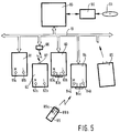
- FIG 5 an embodiment of a system in accordance with the invention is shown, which embodiment comprises a separate configuration unit 80.
- the configuration unit 80 serves to assign unit addresses to the equipment and actuator units 81, 82, 83, respectively and 84 and makes it possible to limit connections between units to connections that are useful.
- the actuator and equipment units are provided with mark-switches 81a, 82a, 83a and 84a and link-switches 81b, 82b, 83b and 84b, respectively.
- Initialising the system or adding a new equipment or actuator unit to the system proceeds as follows.
- the new unit When a new unit 85 is added to the system, the new unit will transmit a message to the configuration unit 80 via the common communication channel 10.
- the configuration unit 80 has a predetermined address which is known to the new unit. With this message the new unit 85 will make itself known to the configuration unit 80 and also indicate of which type it is, for example, switch, thermostat, light or television-set.
- a message is returned by the configuration unit 80 communicating the unit address of the new unit 85 to it. This unit address is stored internally in the new unit.
- each unit is associated with a further programmable memory containing the event table, preferably comprised inside the unit.
- Cooperation between units is established by filling the event table with addresses and, if relevant, with instructions.
- cooperation between an actuator unit 81 and a plurality of equipment units 83, 84 and 85 is established by the following procedure.
- the mark-switches 83a, 84a and 85a of the equipment units are activated.
- Activation of mark-switch 83a causes the unit 83 to transmit a mark-message to the configuration unit 80, which message comprises the type of the unit, the unit address and the present state of the unit 83.
- the unit 83 is now marked by storing its address, state and type in a memory in the configuration unit 80.
- the other unit 84 and 85 are marked analogous by activating the mark-switches 84a and 85a, respectively, thereby building a table of marked units in the configuration unit.
- the actuator unit 81 to be coupled with the equipment units 83, 84 and 85, is selected by means of activating its link-switch 81b. This causes a link-message to be transmitted to the configuration unit 80.
- the link message comprising the type of unit 81, its address and the state it is in.
- an event table will be generated by configuration unit 80 with as input the table of marked units 83, 84 and 85 and the contents of the link-message from unit 81.
- an interface description between any pair of marked and linked unit types can be used.
- the interface description contains the behaviour between a pair of unit types when cooperating. Without an interface description for a particular pair of unit types, no entry will be generated in the event table.
- the interface description, together with the states of the two units is assembled to form the instruction to be entered in the event table.
- the entries are transmitted via the common communication channel 10 to the actuator unit 81 associated with the link signal, to replace, update or supplement the existing event table.
- An analogous procedure can be performed when the mark-signals originate from actuator units and the link-signal is generated in an equipment.
- the event tables in the marked units may be updated with address and instruction for the linking unit. This allows a cross-link and return communication between the units.
- the interface descriptions are available from a background memory 90 connected to the configuration unit 80.
- the contents of the background memory should be replaceable, for example when new types of equipment and actuator units become available.
- the background memory is an exchangeable magnetic or optical storage medium, such as a floppy disc, a CD-ROM, a card with a magnetic strip or a build-in semiconductor chip memory.
- the configuration unit contains an erasable memory, for example a build-in magnetic disc or semi-conductor memory, that can be updated from an exchangeable medium.
- the mark and link signals may be generated by means of a remote control unit 89.
- the remote control unit 89 cooperates with detectors in the actuator and equipment units.
- units 83 and 84 are provided with detectors 83c and 84c, respectively.
- the remote control unit 89 is of the "point and shoot" type having a narrow beam. Aiming the remote control unit 89 towards the detector, 83c or 84c, and activating the mark button 89a or the link-button 89b, activates the mark or link signal generating circuit connected to detectors 83c and 84b in the units 83 and 84, respectively.
- a "point and shoot" type of remote control unit makes it unnecessary to provide buttons on the remote control unit to identify the equipment or actuator by means of an address and, more importantly, it relieves the user of the need to memorise those addresses or look for them beforehand.
- the common communication channel 10 may comprise a variety of transmission possibilities.
- the connection of unit 82 is partially via two-way infra-red communication, indicated by a IR-transmitter/receiver 86 connected to the common communication channel 10 and a transmitter/receiver 87 connected to the unit 82.
- the means to mark en link the units in creating a system configuration use the same common communication channel 10 as the messages between the actuator and equipment units when the system is operating normally.
- the common communication channel 10 may be a wired bus
- the configuration unit is a portable device communicating with each of the units by means of two-way IR.
- a "point and shoot" remote control unit can be integrated with this portable device. Marking and linking units will cause not a mark-link signal on the common communication channel but transmitting the mark- and link-signals to the portable configuration unit wirelessly and the assembled event table is transmitted along the same route.
- a graphic interface is illustrated to facilitate interaction of a user with the equipment control system.
- the graphical user interface 100 is a combination of an actuator unit and an equipment unit, not unlike other units.
- the graphical interface contains a keypad 101 and/or a pointing device 105 and a screen 102, for example an LCD-screen.
- the screen and input devices may be integrated, for example in a touch-sensitive screen.
- the graphical interface comprises further a programmable memory, for storing an event table.
- the graphical user interface 100 is logically connected to all equipment and actuator units in the system or to all units in a functional portion of the system, for example all units in a particular room or in a section of a building.
- the user interface comprises means for remotely marking all units in the system and generating a link signal for itself.
- the programmable memory in the graphical user interface 100 comprises an extended event table.
- the programmable memory may further comprise a table of unit addresses and names or labels or icons for all equipment and actuator units in the functional portion of the system coupled to the graphical user interface. Initially the names are assigned by the system, and divided, for example, of a combination of type and a number. The labels or icons can be changed via the keypad 101. Instructions in the extended event table do not only cause an equipment unit to change state, but may cause other changes in the equipment or actuator units. In combination with "mark" and "link” keys 103 and 104 on the keypad 101, and with the label attached to each equipment and actuator unit the units can be remotely caused to generate mark- and link-signals.
- equipment and actuator units themselves are also provided with a programmable memory containing such name
- a change in the name of a unit entered by a user via a graphical user interface will cause the name in the equipment or actuator unit to be changed.
- This change of name is handled in the unit as a change in state and causes further messages to be send to inform all other relevant units about the change of name. Consequently, entering a new name via one graphical user interface will change the name on all displays in the whole system.
- a change in operational state of an equipment or actuator unit is communicated to the graphical user interface 100 and made visible by a symbol on the screen 102. The screen will show all units, or a selected portion, in their present states.
- the only information that an equipment and actuator unit contains about other equipment and actuator units is comprised in the event table.
- the event table is filled with instructions for other units, these instructions are loaded or changed when the system is initialised or reconfigured.
- the instructions have no meaning to the unit in the programmable memory of which they are stored.
- the central or configuration unit is only needed during initialisation or reconfiguration. No messages are send to or received from the central unit during normal operation.
Landscapes
- Physics & Mathematics (AREA)
- General Physics & Mathematics (AREA)
- Selective Calling Equipment (AREA)
- Programmable Controllers (AREA)
Priority Applications (1)
| Application Number | Priority Date | Filing Date | Title |
|---|---|---|---|
| EP19920203386 EP0549005B1 (de) | 1991-11-11 | 1992-11-04 | System zur Anlagensteuerung mit einem gemeinsamen Kommunikationskanal |
Applications Claiming Priority (3)
| Application Number | Priority Date | Filing Date | Title |
|---|---|---|---|
| EP91202937 | 1991-11-11 | ||
| EP91202937 | 1991-11-11 | ||
| EP19920203386 EP0549005B1 (de) | 1991-11-11 | 1992-11-04 | System zur Anlagensteuerung mit einem gemeinsamen Kommunikationskanal |
Publications (2)
| Publication Number | Publication Date |
|---|---|
| EP0549005A1 true EP0549005A1 (de) | 1993-06-30 |
| EP0549005B1 EP0549005B1 (de) | 1999-03-17 |
Family
ID=26129466
Family Applications (1)
| Application Number | Title | Priority Date | Filing Date |
|---|---|---|---|
| EP19920203386 Expired - Lifetime EP0549005B1 (de) | 1991-11-11 | 1992-11-04 | System zur Anlagensteuerung mit einem gemeinsamen Kommunikationskanal |
Country Status (1)
| Country | Link |
|---|---|
| EP (1) | EP0549005B1 (de) |
Cited By (12)
| Publication number | Priority date | Publication date | Assignee | Title |
|---|---|---|---|---|
| EP0751638A2 (de) * | 1995-06-26 | 1997-01-02 | Abb Research Ltd. | Informationsübertragungseinrichtung mit optischem Informationsverteiler |
| EP0776108A3 (de) * | 1995-11-25 | 1998-06-17 | Bernward Zimmermann | Bussystem, insbesondere zur elektrischen Installation |
| EP0849652A1 (de) * | 1996-12-18 | 1998-06-24 | Robert Bosch Gmbh | Verfahren zur Verwaltung von Weckzeiten und Vorrichtung zur Ausführung dieses Verfahrens |
| DE19651308A1 (de) * | 1996-12-10 | 1998-07-16 | Becker Gmbh | Audio-Soundsystem für ein Kraftfahrzeug |
| DE19715028A1 (de) * | 1997-04-11 | 1998-10-29 | Insta Elektro Gmbh & Co Kg | Busfähige Geräte, insbesondere Dimmer, elektronische Transformatoren oder Vorschaltgeräte |
| FR2770014A1 (fr) * | 1997-10-20 | 1999-04-23 | Schneider Electric Sa | Procede de commande pour une installation electrique comportant des modules communiquants, dispositif et installation mettant en oeuvre un tel procede |
| GB2372609A (en) * | 2000-09-01 | 2002-08-28 | Linsong Weng | Wireless remote control bulb device |
| WO2003042947A2 (en) * | 2001-11-15 | 2003-05-22 | Attila Murlasits | Method and apparatus for controlling operation of electric appliances |
| EP1065830B1 (de) * | 1999-06-28 | 2006-06-28 | Schneider Electric Industries SAS | System zur Konfigurierung eines Hausnetzs |
| DE19505684B4 (de) * | 1995-02-20 | 2009-04-09 | BSH Bosch und Siemens Hausgeräte GmbH | Steuerungssystem zur Ansteuerung von Einrichtungen im Haushaltsbereich |
| WO2012177217A1 (en) | 2011-06-23 | 2012-12-27 | Zoliex Ab | A control method in a network |
| EP0947897B2 (de) † | 1998-04-01 | 2015-04-01 | Robert Bosch Gmbh | Bussystem, insbesondere für eine Hausautomatisierungseinrichtung |
Citations (4)
| Publication number | Priority date | Publication date | Assignee | Title |
|---|---|---|---|---|
| DE3611949A1 (de) * | 1986-04-09 | 1987-10-15 | Regulex Tech Info | Datenuebertragungsverfahren und datenuebertragungsvorrichtung |
| EP0296022A1 (de) * | 1987-06-17 | 1988-12-21 | René Duranton | Busadressierungsvorrichtung |
| WO1989004578A1 (en) * | 1987-11-10 | 1989-05-18 | Echelon Systems | Network and intelligent cell for providing sensing, bidirectional communications and control |
| EP0453399A1 (de) * | 1990-04-17 | 1991-10-23 | Somfy | Einrichtung mit einer Vielzahl von Empfängern und Sendern |
-
1992
- 1992-11-04 EP EP19920203386 patent/EP0549005B1/de not_active Expired - Lifetime
Patent Citations (4)
| Publication number | Priority date | Publication date | Assignee | Title |
|---|---|---|---|---|
| DE3611949A1 (de) * | 1986-04-09 | 1987-10-15 | Regulex Tech Info | Datenuebertragungsverfahren und datenuebertragungsvorrichtung |
| EP0296022A1 (de) * | 1987-06-17 | 1988-12-21 | René Duranton | Busadressierungsvorrichtung |
| WO1989004578A1 (en) * | 1987-11-10 | 1989-05-18 | Echelon Systems | Network and intelligent cell for providing sensing, bidirectional communications and control |
| EP0453399A1 (de) * | 1990-04-17 | 1991-10-23 | Somfy | Einrichtung mit einer Vielzahl von Empfängern und Sendern |
Cited By (17)
| Publication number | Priority date | Publication date | Assignee | Title |
|---|---|---|---|---|
| DE19505684B4 (de) * | 1995-02-20 | 2009-04-09 | BSH Bosch und Siemens Hausgeräte GmbH | Steuerungssystem zur Ansteuerung von Einrichtungen im Haushaltsbereich |
| EP0751638A3 (de) * | 1995-06-26 | 1998-01-14 | Abb Research Ltd. | Informationsübertragungseinrichtung mit optischem Informationsverteiler |
| EP0751638A2 (de) * | 1995-06-26 | 1997-01-02 | Abb Research Ltd. | Informationsübertragungseinrichtung mit optischem Informationsverteiler |
| EP0776108A3 (de) * | 1995-11-25 | 1998-06-17 | Bernward Zimmermann | Bussystem, insbesondere zur elektrischen Installation |
| DE19651308A1 (de) * | 1996-12-10 | 1998-07-16 | Becker Gmbh | Audio-Soundsystem für ein Kraftfahrzeug |
| DE19651308C2 (de) * | 1996-12-10 | 1998-10-22 | Becker Gmbh | Audio-Soundsystem für ein Kraftfahrzeug |
| EP0849652A1 (de) * | 1996-12-18 | 1998-06-24 | Robert Bosch Gmbh | Verfahren zur Verwaltung von Weckzeiten und Vorrichtung zur Ausführung dieses Verfahrens |
| DE19715028B4 (de) * | 1997-04-11 | 2008-07-03 | Insta Elektro Gmbh | Busfähige Dimmer, elektronische Transformatoren und Vorschaltgeräte zur Helligkeitssteuerung von Leuchten |
| DE19715028A1 (de) * | 1997-04-11 | 1998-10-29 | Insta Elektro Gmbh & Co Kg | Busfähige Geräte, insbesondere Dimmer, elektronische Transformatoren oder Vorschaltgeräte |
| EP0911777A1 (de) * | 1997-10-20 | 1999-04-28 | Schneider Electric Sa | Steuerverfahren für Elektroinstallation mit kommunizierenden Modulen, Vorrichtung und Installation zur Ausführung des Verfahrens |
| FR2770014A1 (fr) * | 1997-10-20 | 1999-04-23 | Schneider Electric Sa | Procede de commande pour une installation electrique comportant des modules communiquants, dispositif et installation mettant en oeuvre un tel procede |
| EP0947897B2 (de) † | 1998-04-01 | 2015-04-01 | Robert Bosch Gmbh | Bussystem, insbesondere für eine Hausautomatisierungseinrichtung |
| EP1065830B1 (de) * | 1999-06-28 | 2006-06-28 | Schneider Electric Industries SAS | System zur Konfigurierung eines Hausnetzs |
| GB2372609A (en) * | 2000-09-01 | 2002-08-28 | Linsong Weng | Wireless remote control bulb device |
| WO2003042947A2 (en) * | 2001-11-15 | 2003-05-22 | Attila Murlasits | Method and apparatus for controlling operation of electric appliances |
| WO2003042947A3 (en) * | 2001-11-15 | 2003-11-06 | Attila Murlasits | Method and apparatus for controlling operation of electric appliances |
| WO2012177217A1 (en) | 2011-06-23 | 2012-12-27 | Zoliex Ab | A control method in a network |
Also Published As
| Publication number | Publication date |
|---|---|
| EP0549005B1 (de) | 1999-03-17 |
Similar Documents
| Publication | Publication Date | Title |
|---|---|---|
| US5537104A (en) | System for equipment control, comprising a common communication channel | |
| EP0549005B1 (de) | System zur Anlagensteuerung mit einem gemeinsamen Kommunikationskanal | |
| US5519878A (en) | System for installing and configuring (grouping and node address assignment) household devices in an automated environment | |
| US6856236B2 (en) | RF home automation system comprising nodes with dual functionality | |
| JP5027312B2 (ja) | ホームネットワークシステム | |
| US6998955B2 (en) | Virtual electronic remote control device | |
| JP2003009261A (ja) | オートメーションシステムにおけるルーティングテーブル構築および信号ルーティングのためのシステムおよび方法 | |
| JP2004500668A (ja) | コンピュータと埋め込み装置をネットワークに接続する装置インターフェース | |
| JPH05161178A (ja) | ビルディング管理機構 | |
| KR950033883A (ko) | 정보단말장치 | |
| JP2004135351A (ja) | 乱数発生型ホームネットワークシステム及びその制御方法 | |
| US4488148A (en) | Combination switching and display electronic modular control unit | |
| KR100385185B1 (ko) | 냉장고를 이용한 홈네트워크 시스템 및 그 제어방법 | |
| JP4429493B2 (ja) | 双方向リモートコントロールシステムと遠隔制御装置及び被制御装置 | |
| JPS61201571A (ja) | リモ−トコントロ−ル装置 | |
| WO2008084356A1 (en) | Network communication system | |
| EP0495251B1 (de) | Lokales Kommunikationssystem und Rahmenbilder einschliesslich eines programmierbaren Adressgenerators | |
| WO2012015437A1 (en) | Distributed control system operation and configuration | |
| JPH09261769A (ja) | 建物設備用統合リモコン装置 | |
| JP2783098B2 (ja) | 遠隔制御システム | |
| JPH09210432A (ja) | 空調管理システム | |
| JP3382106B2 (ja) | 遠隔監視制御装置 | |
| JP2000125373A (ja) | リモートコントローラ、被制御機器、およびリモートコントロールシステム | |
| JPH0413903Y2 (de) | ||
| JP2004193688A (ja) | 遠隔制御システム |
Legal Events
| Date | Code | Title | Description |
|---|---|---|---|
| PUAI | Public reference made under article 153(3) epc to a published international application that has entered the european phase |
Free format text: ORIGINAL CODE: 0009012 |
|
| AK | Designated contracting states |
Kind code of ref document: A1 Designated state(s): DE FR GB IT NL |
|
| 17P | Request for examination filed |
Effective date: 19931222 |
|
| 17Q | First examination report despatched |
Effective date: 19961122 |
|
| GRAG | Despatch of communication of intention to grant |
Free format text: ORIGINAL CODE: EPIDOS AGRA |
|
| RAP3 | Party data changed (applicant data changed or rights of an application transferred) |
Owner name: KONINKLIJKE PHILIPS ELECTRONICS N.V. |
|
| GRAG | Despatch of communication of intention to grant |
Free format text: ORIGINAL CODE: EPIDOS AGRA |
|
| GRAH | Despatch of communication of intention to grant a patent |
Free format text: ORIGINAL CODE: EPIDOS IGRA |
|
| GRAH | Despatch of communication of intention to grant a patent |
Free format text: ORIGINAL CODE: EPIDOS IGRA |
|
| GRAA | (expected) grant |
Free format text: ORIGINAL CODE: 0009210 |
|
| AK | Designated contracting states |
Kind code of ref document: B1 Designated state(s): DE FR GB IT NL |
|
| PG25 | Lapsed in a contracting state [announced via postgrant information from national office to epo] |
Ref country code: IT Free format text: LAPSE BECAUSE OF FAILURE TO SUBMIT A TRANSLATION OF THE DESCRIPTION OR TO PAY THE FEE WITHIN THE PRESCRIBED TIME-LIMIT;WARNING: LAPSES OF ITALIAN PATENTS WITH EFFECTIVE DATE BEFORE 2007 MAY HAVE OCCURRED AT ANY TIME BEFORE 2007. THE CORRECT EFFECTIVE DATE MAY BE DIFFERENT FROM THE ONE RECORDED. Effective date: 19990317 Ref country code: NL Free format text: LAPSE BECAUSE OF FAILURE TO SUBMIT A TRANSLATION OF THE DESCRIPTION OR TO PAY THE FEE WITHIN THE PRESCRIBED TIME-LIMIT Effective date: 19990317 |
|
| REF | Corresponds to: |
Ref document number: 69228664 Country of ref document: DE Date of ref document: 19990422 |
|
| ET | Fr: translation filed | ||
| NLV1 | Nl: lapsed or annulled due to failure to fulfill the requirements of art. 29p and 29m of the patents act | ||
| PLBE | No opposition filed within time limit |
Free format text: ORIGINAL CODE: 0009261 |
|
| STAA | Information on the status of an ep patent application or granted ep patent |
Free format text: STATUS: NO OPPOSITION FILED WITHIN TIME LIMIT |
|
| 26N | No opposition filed | ||
| REG | Reference to a national code |
Ref country code: GB Ref legal event code: IF02 |
|
| REG | Reference to a national code |
Ref country code: GB Ref legal event code: 746 Effective date: 20020917 |
|
| REG | Reference to a national code |
Ref country code: FR Ref legal event code: D6 |
|
| PGFP | Annual fee paid to national office [announced via postgrant information from national office to epo] |
Ref country code: FR Payment date: 20041125 Year of fee payment: 13 |
|
| PGFP | Annual fee paid to national office [announced via postgrant information from national office to epo] |
Ref country code: GB Payment date: 20041129 Year of fee payment: 13 |
|
| PGFP | Annual fee paid to national office [announced via postgrant information from national office to epo] |
Ref country code: DE Payment date: 20050118 Year of fee payment: 13 |
|
| PG25 | Lapsed in a contracting state [announced via postgrant information from national office to epo] |
Ref country code: GB Free format text: LAPSE BECAUSE OF NON-PAYMENT OF DUE FEES Effective date: 20051104 |
|
| PG25 | Lapsed in a contracting state [announced via postgrant information from national office to epo] |
Ref country code: DE Free format text: LAPSE BECAUSE OF NON-PAYMENT OF DUE FEES Effective date: 20060601 |
|
| GBPC | Gb: european patent ceased through non-payment of renewal fee |
Effective date: 20051104 |
|
| PG25 | Lapsed in a contracting state [announced via postgrant information from national office to epo] |
Ref country code: FR Free format text: LAPSE BECAUSE OF NON-PAYMENT OF DUE FEES Effective date: 20060731 |
|
| REG | Reference to a national code |
Ref country code: FR Ref legal event code: ST Effective date: 20060731 |