EP0548604A1 - Plate type heat-exchanger - Google Patents
Plate type heat-exchanger Download PDFInfo
- Publication number
- EP0548604A1 EP0548604A1 EP92120520A EP92120520A EP0548604A1 EP 0548604 A1 EP0548604 A1 EP 0548604A1 EP 92120520 A EP92120520 A EP 92120520A EP 92120520 A EP92120520 A EP 92120520A EP 0548604 A1 EP0548604 A1 EP 0548604A1
- Authority
- EP
- European Patent Office
- Prior art keywords
- plate
- another
- medium
- inflow
- media
- Prior art date
- Legal status (The legal status is an assumption and is not a legal conclusion. Google has not performed a legal analysis and makes no representation as to the accuracy of the status listed.)
- Granted
Links
Images

Classifications
-
- F—MECHANICAL ENGINEERING; LIGHTING; HEATING; WEAPONS; BLASTING
- F28—HEAT EXCHANGE IN GENERAL
- F28F—DETAILS OF HEAT-EXCHANGE AND HEAT-TRANSFER APPARATUS, OF GENERAL APPLICATION
- F28F3/00—Plate-like or laminated elements; Assemblies of plate-like or laminated elements
-
- F—MECHANICAL ENGINEERING; LIGHTING; HEATING; WEAPONS; BLASTING
- F28—HEAT EXCHANGE IN GENERAL
- F28D—HEAT-EXCHANGE APPARATUS, NOT PROVIDED FOR IN ANOTHER SUBCLASS, IN WHICH THE HEAT-EXCHANGE MEDIA DO NOT COME INTO DIRECT CONTACT
- F28D9/00—Heat-exchange apparatus having stationary plate-like or laminated conduit assemblies for both heat-exchange media, the media being in contact with different sides of a conduit wall
- F28D9/0031—Heat-exchange apparatus having stationary plate-like or laminated conduit assemblies for both heat-exchange media, the media being in contact with different sides of a conduit wall the conduits for one heat-exchange medium being formed by paired plates touching each other
- F28D9/0037—Heat-exchange apparatus having stationary plate-like or laminated conduit assemblies for both heat-exchange media, the media being in contact with different sides of a conduit wall the conduits for one heat-exchange medium being formed by paired plates touching each other the conduits for the other heat-exchange medium also being formed by paired plates touching each other
-
- F—MECHANICAL ENGINEERING; LIGHTING; HEATING; WEAPONS; BLASTING
- F28—HEAT EXCHANGE IN GENERAL
- F28F—DETAILS OF HEAT-EXCHANGE AND HEAT-TRANSFER APPARATUS, OF GENERAL APPLICATION
- F28F9/00—Casings; Header boxes; Auxiliary supports for elements; Auxiliary members within casings
- F28F9/02—Header boxes; End plates
-
- F—MECHANICAL ENGINEERING; LIGHTING; HEATING; WEAPONS; BLASTING
- F28—HEAT EXCHANGE IN GENERAL
- F28F—DETAILS OF HEAT-EXCHANGE AND HEAT-TRANSFER APPARATUS, OF GENERAL APPLICATION
- F28F9/00—Casings; Header boxes; Auxiliary supports for elements; Auxiliary members within casings
- F28F9/26—Arrangements for connecting different sections of heat-exchange elements, e.g. of radiators
Definitions
- the invention relates to a plate heat exchanger for media carried in cocurrent or countercurrent.
- Such plate heat exchangers are known, they consist of shaped single plates which are connected to one another to form a flow channel for the plate pairs forming a medium, which in turn are joined to form a plate stack and each form a flow channel for the other medium.
- the inflow and outflow cross-sections of each flow channel are offset diagonally to one another in the main flow direction.
- the inflow and outflow cross sections of the channels for the two media lie next to one another, but are offset from one another by half the height of the inflow and outflow cross sections of the channels.
- the invention has for its object to develop a plate heat exchanger of the type described above in such a way that with complete separation of the media participating in the heat exchange and with low pressure loss guidance of the media, a space-saving and compact design results, which furthermore the use of similar modules for individual adaptation of the heat exchange surfaces and the materials to the respective operating conditions and, in addition to good accessibility for maintenance purposes, creates an easy exchange option for the modules for repair purposes.
- the solution to this problem by the invention is characterized in that a plurality of similar plate stacks are arranged directly next to one another, that the inflow and outflow cross sections of each plate stack are separated from one another by a central wall extending over the entire stack length, and that the central walls of adjacent plate stacks are each covered by a ceiling wall are connected to a common collecting duct and that these collecting ducts are connected alternately and with inclusion of the inflow or outflow cross sections of the two end-side plate stacks with a common inflow or outflow connection piece for each of the two media.
- each plate stack consists of shaped individual plates, which are connected to each other to form pairs of plates, which in turn are assembled to form a plate stack
- the heat exchanger according to the invention can be adapted to the operating conditions in a simple and inexpensive manner by using appropriate materials or coating the individual plates, so that the The plate heat exchanger of the invention is also used, for example, for aggressive media or media loaded with solid particles can be. Since the one medium is guided in the flow channels, which are formed by the formation of plate pairs, and the channels for the other medium are formed by the connection of the plate pairs to a plate stack, there is a slip-free separation of the media participating in the heat exchange, which in particular results in pollutant emissions leakages or solid matter transfer.
- the plate heat exchanger according to the invention Since the media guided in cocurrent or in countercurrent to one another are fed without deflection to the plate stacks arranged next to one another, the plate heat exchanger according to the invention operates with low pressure losses and with relatively low gas velocities and without drives and moving parts, so that no additional noise emissions are generated. Even when installing a cleaning system that may be required, normal sound insulation without a complex housing for the plate heat exchanger is sufficient.
- modules of the same type and a maximum of two different individual plates enables inexpensive production and simple assembly; in addition, it facilitates the adaptation of the heat exchange surface to the respective operating conditions, because the plate heat exchanger according to the invention can be varied particularly simply with regard to its heat exchange performance by changing the number of individual plates joined to form a plate stack and on the other hand by changing the number of plate stacks arranged side by side.
- the collecting duct results in favorable inflow and outflow conditions of the media participating in the heat exchange to the heat exchange surface formed by the plate stack. Since the middle and ceiling walls connected to common collecting channels can be removed without problems, there is good access to the plate stacks for maintenance and repair purposes, with repair being facilitated in that complete modules can be exchanged. In addition to loss-free flow control and good accessibility, the collecting channels formed by central and ceiling walls also provide the possibility of installing any cleaning device that may be required.
- This also has the advantage that the cleaning process can run in the direction of flow and that there is the possibility of guiding the cleaning agent, for example air, superheated steam or water, vertically from above through the stack of plates, so that no problems arise when collecting the cleaning medium contaminated with residues .
- the cleaning agent for example air, superheated steam or water
- the plate heat exchanger designed according to the invention leaves several options for the supply and removal of those participating in the heat exchange Media too.
- the inlet connection and the outlet connection for each medium can either be arranged at the same end of the adjacent stack of plates or at the other end of the adjacent stack of plates. The supply and removal of each medium can thus either take place on the same side of the plate heat exchanger or lead to a crossing of the media within the plate heat exchanger, regardless of whether the two media are in cocurrent or countercurrent to each other and whether the supply is from below or above.
- the invention proposes to design the ceiling walls of the collecting ducts to run obliquely.
- FIG. 1 The embodiment of a plate heat exchanger shown schematically in FIG. 1 shows in perspective a plate stack S composed of a plurality of shaped individual plates 1, which are each connected to one another to form a plate pair P.
- Each individual plate 1 comprises a floor 11 which lies in a different plane than the longitudinal edges 12.
- each individual plate 1 is each with a Contact surface 13 formed, which is offset in height from the longitudinal edges 12.
- the offset between the contact surface 13 and the associated longitudinal edge 12 is twice as large as the offset between the longitudinal edges 12 and the bottom 11.
- the bottom 11 is therefore located in the middle between the plane of the longitudinal edges 12 and the plane of the contact surfaces 13.
- transverse edges 14a and 14b are diagonally opposite one another.
- FIG. 1 Two of the individual plates 1 shown as the uppermost part in FIG. 1 are connected to plate pairs P according to the lower representation in FIG. 1.
- Fig. 1 five complete plate pairs P are shown, with a single plate 1 being arranged on the top pair of plates, which is also connected to the top single plate 1 shown at a distance to form a plate pair P.
- the plate pairs P are connected in the area of the contact surfaces 13 to form the plate stack S, superimposed channels result for the two media participating in the heat exchange. While one medium flows in the flow channels, which are each formed by the plate pairs P, the other medium flows in the flow channels, which result from the joining of the plate pairs P to the plate stack S.
- the transverse edges lying in the plane of the longitudinal edges 12 14a of the individual plates 1 here form the inflow cross section Z 1 or the outflow cross section A 1 of the flow channels for the medium flowing between the plate pairs P.
- Fig. 1 which shows a counterflow heat exchanger, shows that due to the diagonal arrangement of the inlet and outlet openings, the inflow cross sections Z1 and Z2 for one medium next to the outflow cross sections A2 and A1 for the other medium, respectively offset by half a height of a pair of plates P.
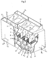
- the plate heat exchanger shown in perspective in FIG. 2 has two media I and II flowing through it in direct current, medium I being, for example, the heat-emitting medium and medium II the heat-absorbing medium.
- medium I being, for example, the heat-emitting medium and medium II the heat-absorbing medium.
- the heat exchange between the two media I and II takes place in plate stacks S which, according to FIG. 1, are formed from individual plates combined into plate pairs.
- These plate stacks S are arranged directly next to one another in such a way that their inflow cross sections Z 1, Z 2 are perpendicularly above the outflow cross sections A 1, A 2, as the section in FIG. 2 clearly shows.
- the inflow and outflow cross-sections belonging to one of the two media I or II are diagonally offset from one another, as can again be seen in FIG. 1.
- the inflow and outflow cross sections Z1, Z2 and A1, A2 of each plate stack S are separated from each other by a central wall 21 which extends over the entire length of the plate stack S.
- the middle walls 21 of adjacent plate stacks S are each connected to a common collecting duct 2 by a ceiling wall 22.
- these collecting channels 2 represent a supply or discharge of the medium I or II to or from respectively adjacent two plate stacks S.
- This inflow nozzle 3 1 is connected to those collecting channels 2 which open above the inflow cross sections Z 1 of the plate stack S.
- the streams of the medium I divide and get into the collecting channels 2 formed below the plate stack S, which lead the medium I to the outflow nozzle 4 1, which is arranged in the embodiment according to FIG. 2 below the inflow nozzle 3 1.
- the heat-absorbing medium II enters the inflow nozzle 32 from above and arrives from here into collecting channels 2, which lead to the inflow cross sections Z2 of the plate stack S.
- the partial flows of the medium 2 are divided in the plate stacks S and arrive in collecting channels 2, which in turn lead to an outflow nozzle 42, which is formed vertically below the inflow nozzle 32.
- the top walls 22 of the collecting channels 2 are designed to run obliquely, as can clearly be seen in the upper part of FIG. 2.
- the in the embodiment 2 realized DC circuit of the two media I and II participating in the heat exchange enables the generation of a surface temperature on the individual plates, which avoids the caking of solids when the media I and II enter the plate stack S as well as falling below the dew point. Should deposit products of the media arise, they can be collected and discharged via the collecting channels 2 and the outlet connections 4 1 and 4 2 below.
- the plate heat exchanger shown in Fig. 2 is accordingly particularly well suited for a recuperative heat exchange in connection with flue gas cleaning systems.
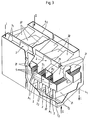
- the plate heat exchanger in Fig. 3 is designed as a countercurrent heat exchanger, in which the heat-emitting medium I according to the dash-dotted arrows from above enters the inflow nozzle 3 1 and from this inflow nozzle 3 1 into the collecting channels 2 connected to it.
- the heat-emitting medium I also divides in this case and emerges from the mutually spaced outflow cross sections A 1 of the plate stack S, namely in the underlying collection channels 2, which in turn are connected to the outflow nozzle 4 1 lying on the opposite side.
- the heat-absorbing medium II enters the inflow nozzle 32 from below and passes through the corresponding collecting channels 2 to the inflow cross sections Z 2 lying on the underside of the plate stack S. After heating the medium II in the plate stacks S, it emerges from the outflow cross sections A2; it passes into the collecting channels 2 above these outflow cross-sections A2, which are connected to the outflow connection 42.
- the inflow and outflow of the heat-absorbing medium II is indicated in Fig. 3 by solid arrows.
- both plate heat exchangers in FIGS. 2 and 3 show that despite a very compact and space-saving design, there is good access to the plate stacks S, which not only facilitates the installation of cleaning devices that may become necessary, but also good access to repairs or Maintenance work enabled.
- both representations show that the flow guidance of the two media I and II takes place in the shortest possible way and without any deflections causing pressure loss, so that the plate heat exchangers described, despite their compactness, are highly efficient.
Abstract
Description
Die Erfindung betrifft einen Plattenwärmetauscher für im Gleichstrom oder Gegenstrom geführte Medien.The invention relates to a plate heat exchanger for media carried in cocurrent or countercurrent.
Derartige Plattenwärmetauscher sind bekannt, sie bestehen aus formgeprägten Einzelplatten, die miteinander zu einen Strömungskanal für das eine Medium bildenden Plattenpaaren verbunden sind, die ihrerseits zu einem Plattenstapel zusammengefügt sind und zwischen sich jeweils einen Strömungskanal für das andere Medium bilden. Hierbei sind der Zu- und Abströmquerschnitt jedes Strömungskanals in Hauptströmungsrichtung diagonal zueinander versetzt. Die Zu- und Abströmquerschnitte der Kanäle für die beiden Medien liegen nebeneinander, sind jedoch um die halbe Höhe des Zu- bzw. Abströmquerschnittes der Kanäle zueinander versetzt.Such plate heat exchangers are known, they consist of shaped single plates which are connected to one another to form a flow channel for the plate pairs forming a medium, which in turn are joined to form a plate stack and each form a flow channel for the other medium. The inflow and outflow cross-sections of each flow channel are offset diagonally to one another in the main flow direction. The inflow and outflow cross sections of the channels for the two media lie next to one another, but are offset from one another by half the height of the inflow and outflow cross sections of the channels.
Der Erfindung liegt die Aufgabe zugrunde, einen Plattenwärmetauscher der voranstehend beschriebenen Art derart weiterzubilden, daß sich bei vollständiger Trennung der am Wärmeaustausch teilnehmenden Medien und bei druckverlustarmer Führung der Medien eine platzsparende und kompakte Bauweise ergibt, die weiterhin die Verwendung gleichartiger Module zur individuellen Anpassung der Wärmetauschflächen und der Materialien an die jeweiligen Einsatzbedingungen ermöglicht und neben einer guten Zugänglichkeit zu Wartungszwecken eine einfache Austauschmöglichkeit der Module zu Reparaturzwecken schafft.The invention has for its object to develop a plate heat exchanger of the type described above in such a way that with complete separation of the media participating in the heat exchange and with low pressure loss guidance of the media, a space-saving and compact design results, which furthermore the use of similar modules for individual adaptation of the heat exchange surfaces and the materials to the respective operating conditions and, in addition to good accessibility for maintenance purposes, creates an easy exchange option for the modules for repair purposes.
Die Lösung dieser Aufgabenstellung durch die Erfindung ist dadurch gekennzeichnet, daß eine Mehrzahl gleichartiger Plattenstapel unmittelbar nebeneinander angeordnet ist, daß die Zu- und Abströmquerschnitte jedes Plattenstapels durch eine über die gesamte Stapellänge verlaufende Mittelwand voneinander getrennt sind, daß die Mittelwände benachbarter Plattenstapel jeweils durch eine Deckenwand zu einem gemeinsamen Sammelkanal verbunden sind und daß diese Sammelkanäle abwechselnd und unter Einbeziehung der Zu- bzw. Abströmquerschnitte der beiden endseitigen Plattenstapel mit einem gemeinsamen Zuström- bzw. Abströmstutzen für jeweils eines der beiden Medien verbunden sind.The solution to this problem by the invention is characterized in that a plurality of similar plate stacks are arranged directly next to one another, that the inflow and outflow cross sections of each plate stack are separated from one another by a central wall extending over the entire stack length, and that the central walls of adjacent plate stacks are each covered by a ceiling wall are connected to a common collecting duct and that these collecting ducts are connected alternately and with inclusion of the inflow or outflow cross sections of the two end-side plate stacks with a common inflow or outflow connection piece for each of the two media.
Durch diese erfindungsgemäße Ausgestaltung eines im Gleich- oder Gegenstrom betreibbaren Plattenwärmetauschers ergibt sich eine sehr platzsparende und kompakte Bauweise, da die Wärmetauschfläche durch mehrere gleichartige Plattenstapel gebildet wird, die unmittelbar nebeneinander angeordnet sind. Hierdurch ergibt sich für den erfindungsgemäßen Plattenwärmetauscher die geringstmögliche Grundfläche, weil Zwischenräume zwischen den einzelnen Plattenstapeln zur Zufuhr bzw. Abfuhr der am Wärmeaustausch teilnehmenden Medien entfallen. Durch die Anzahl der jeweils nebeneinander in der Art von Modulen angeordneten Plattenstapel läßt sich die Größe der Wärmetauschfläche auf einfache Weise an den jeweiligen Bedarf anpassen.This inventive design of a plate heat exchanger which can be operated in cocurrent or countercurrent results in a very space-saving and compact construction, since the heat exchange surface is formed by a plurality of plate stacks of the same type which are arranged directly next to one another. This results in the smallest possible base area for the plate heat exchanger according to the invention, because there are no spaces between the individual plate stacks for supplying or removing the media participating in the heat exchange. The number of plate stacks arranged side by side in the manner of modules makes it easy to adapt the size of the heat exchange surface to the respective requirements.
Da jeder Plattenstapel aus formgeprägten Einzelplatten besteht, die zueinander zu Plattenpaaren verbunden sind, die ihrerseits zum Plattenstapel zusammengefügt werden, läßt sich durch die Verwendung entsprechender Materialien bzw. Beschichtung der Einzelplatten der erfindungsgemäße Wärmetauscher auf einfache und kostengünstige Weise an die Einsatzbedingungen anpassen, so daß der Plattenwärmetauscher der Erfindung beispielsweise auch für aggressive oder mit Feststoffpartikeln beladene Medien verwendet werden kann. Da das eine Medium in den Strömungskanälen geführt wird, die durch die Bildung von Plattenpaaren entstehen, und die Kanäle für das andere Medium durch die Verbindung der Plattenpaare zu einem Plattenstapel entstehen, ergibt sich eine schlupffreie Trennung der am Wärmeaustausch teilnehmenden Medien, wodurch insbesondere Schadstoffemissionen infolge von Leckagen oder Feststoffübertragungen ausgeschlossen werden.Since each plate stack consists of shaped individual plates, which are connected to each other to form pairs of plates, which in turn are assembled to form a plate stack, the heat exchanger according to the invention can be adapted to the operating conditions in a simple and inexpensive manner by using appropriate materials or coating the individual plates, so that the The plate heat exchanger of the invention is also used, for example, for aggressive media or media loaded with solid particles can be. Since the one medium is guided in the flow channels, which are formed by the formation of plate pairs, and the channels for the other medium are formed by the connection of the plate pairs to a plate stack, there is a slip-free separation of the media participating in the heat exchange, which in particular results in pollutant emissions leakages or solid matter transfer.
Da die im Gleichstrom oder im Gegenstrom zueinander geführten Medien ohne Umlenkung den nebeneinander angeordneten Plattenstapeln zugeführt werden, arbeitet der erfindungsgemäße Plattenwärmetauscher mit niedrigen Druckverlusten und mit relativ niedrigen Gasgeschwindigkeiten sowie ohne Antriebe und bewegliche Teile, so daß keine zusätzlichen Geräuschemissionen erzeugt werden. Selbst bei Einbau einer eventuell erforderlichen Reinigungsanlage reicht somit eine normale Schallisolierung ohne eine aufwendige Einhausung des Plattenwärmetauschers aus.Since the media guided in cocurrent or in countercurrent to one another are fed without deflection to the plate stacks arranged next to one another, the plate heat exchanger according to the invention operates with low pressure losses and with relatively low gas velocities and without drives and moving parts, so that no additional noise emissions are generated. Even when installing a cleaning system that may be required, normal sound insulation without a complex housing for the plate heat exchanger is sufficient.
Die Verwendung gleichartiger Module und maximal zweier unterschiedlicher Einzelplatten ermöglicht eine preisgünstige Herstellung und einfache Montage; außerdem erleichtert sie die Anpassung der Wärmetauschfläche an die jeweiligen Einsatzbedingungen, weil der erfindungsgemäße Plattenwärmetauscher einerseits durch Veränderung der Anzahl der zu einem Plattenstapel zusammengefügten Einzelplatten und andererseits durch Veränderung der Anzahl der nebeneinander angeordneten Plattenstapel hinsichtlich seiner Wärmetauschleistung besonders einfach variiert werden kann.The use of modules of the same type and a maximum of two different individual plates enables inexpensive production and simple assembly; in addition, it facilitates the adaptation of the heat exchange surface to the respective operating conditions, because the plate heat exchanger according to the invention can be varied particularly simply with regard to its heat exchange performance by changing the number of individual plates joined to form a plate stack and on the other hand by changing the number of plate stacks arranged side by side.
Durch die Trennung der Zuström- und Abströmquerschnitte jedes Plattenstapels durch eine über die gesamte Stapellänge verlaufende Mittelwand und die Verbindung dieser Mittelwände benachbarter Plattenstapel mittels einer Deckenwand zu einem gemeinsamen Sammelkanal ergeben sich bei einfachster Konstruktion günstige Zu- und Abströmverhältnisse der am Wärmeaustausch teilnehmenden Medien zu der durch die Plattenstapel gebildeten Wärmeaustauschfläche. Da die zu gemeinsamen Sammelkanälen verbundenen Mittel- und Deckenwände problemlos entfernt werden können, ergibt sich eine gute Zugänglichkeit zu den Plattenstapeln zu Wartungs- und Reparaturzwecken, wobei eine Reparatur dadurch erleichtert wird, daß komplette Module ausgetauscht werden können. Die durch Mittel- und Deckenwände gebildeten Sammelkanäle ergeben neben einer verlustfreien Strömungsführung und guter Zugänglichkeit auch die Möglichkeit zur Installation einer ggf. benötigten Reinigungseinrichtung. Hierbei ergibt sich weiterhin der Vorteil, daß der Reinigungsvorgang in Strömungsrichtung verlaufen kann und daß die Möglichkeit besteht, das Reinigungsmittel, beispielsweise Luft, Heißdampf oder Wasser senkrecht von oben durch die Plattenstapel zu führen, so daß keine Probleme beim Auffangen des mit Rückständen belasteten Reinigungsmediums entstehen.By separating the inflow and outflow cross sections of each plate stack by means of a central wall running over the entire length of the stack and the connection of these central walls of adjacent plate stacks by means of a ceiling wall to form a common one In the simplest construction, the collecting duct results in favorable inflow and outflow conditions of the media participating in the heat exchange to the heat exchange surface formed by the plate stack. Since the middle and ceiling walls connected to common collecting channels can be removed without problems, there is good access to the plate stacks for maintenance and repair purposes, with repair being facilitated in that complete modules can be exchanged. In addition to loss-free flow control and good accessibility, the collecting channels formed by central and ceiling walls also provide the possibility of installing any cleaning device that may be required. This also has the advantage that the cleaning process can run in the direction of flow and that there is the possibility of guiding the cleaning agent, for example air, superheated steam or water, vertically from above through the stack of plates, so that no problems arise when collecting the cleaning medium contaminated with residues .
Da die Sammelkanäle abwechselnd und unter Einbeziehung der Zu- und Abströmquerschnitte der beiden endseitigen Plattenstapel mit einem gemeinsamen Zuström- bzw. Abströmstutzen für jeweils eines der beiden Medien verbunden sind, läßt der erfindungsgemäß ausgebildete Plattenwärmetauscher mehrere Möglichkeiten für die Zu- und Abfuhr der am Wärmeaustausch teilnehmenden Medien zu. Gemäß weiteren Merkmalen der Erfindung können der Zuströmstutzen und der Abströmstutzen für jedes Medium entweder an dem selben Ende der nebeneinanderliegenden Plattenstapel oder jeweils am anderen Ende der nebeneinanderliegenden Plattenstapel angeordnet sein. Die Zu- und Abfuhr jedes Mediums kann somit entweder auf derselben Seite des Plattenwärmetauschers erfolgen oder innerhalb des Plattenwärmetauschers zu einer Kreuzung der Medien führen, und zwar unabhängig davon, ob die beiden Medien im Gleichstrom oder Gegenstrom zueinander geführt werden und ob die Zufuhr von unten oder oben erfolgt.Since the collecting channels are connected alternately and with inclusion of the inflow and outflow cross sections of the two end-side plate stacks with a common inflow or outflow connection for each of the two media, the plate heat exchanger designed according to the invention leaves several options for the supply and removal of those participating in the heat exchange Media too. According to further features of the invention, the inlet connection and the outlet connection for each medium can either be arranged at the same end of the adjacent stack of plates or at the other end of the adjacent stack of plates. The supply and removal of each medium can thus either take place on the same side of the plate heat exchanger or lead to a crossing of the media within the plate heat exchanger, regardless of whether the two media are in cocurrent or countercurrent to each other and whether the supply is from below or above.
Um innerhalb der durch die Mittel- und Deckenwände gebildeten Sammelkanäle Toträume zu vermeiden und auch insoweit eine raumsparende Konstruktion zu schaffen, wird mit der Erfindung schließlich vorgeschlagen, die Deckenwände der Sammelkanäle schräg verlaufend auszubilden.Finally, in order to avoid dead spaces within the collecting ducts formed by the central and ceiling walls and also to create a space-saving construction, the invention proposes to design the ceiling walls of the collecting ducts to run obliquely.
Auf der Zeichnung sind zwei Ausführungsbeispiele eines erfindungsgemäßen Plattenwärmetauschers dargestellt, und zwar zeigen:
- Fig. 1
- eine perspektivische Ansicht eines Teil eines aus mehreren Einzelplatten gebildeten Plattenstapels,
- Fig. 2
- eine perspektivische Ansicht eines unter Verwendung von Plattenstapeln gemäß Fig. 1 hergestellten Plattenwärmetauschers, der im Gleichstrom von den am Wärmeaustausch teilnehmenden Medien durchströmt wird, und
- Fig. 3
- eine der Fig. 2 entsprechende perspektivische Darstellung eines weiteren Plattenwärmetauschers für im Gegenstrom geführte Medien.
- Fig. 1
- 2 shows a perspective view of part of a plate stack formed from several individual plates,
- Fig. 2
- 2 shows a perspective view of a plate heat exchanger produced using plate stacks according to FIG. 1, through which the media participating in the heat exchange flow in cocurrent, and
- Fig. 3
- a perspective view corresponding to FIG. 2 of a further plate heat exchanger for countercurrent media.
Das in Fig. 1 schematisch dargestellte Ausführungsbeispiel eines Plattenwärmetauschers zeigt perspektivisch einen Plattenstapel S aus einer Mehrzahl formgeprägter Einzelplatten 1, die jeweils miteinander zu einem Plattenpaar P verbunden sind.The embodiment of a plate heat exchanger shown schematically in FIG. 1 shows in perspective a plate stack S composed of a plurality of shaped
Jede Einzelplatte 1 umfaßt einen Boden 11, der in einer anderen Ebene liegt als die Längsränder 12. Im Anschluß und parallel zu diesen Längsrändern 12 ist jede Einzelplatte 1 jeweils mit einer Anlagefläche 13 ausgebildet, die gegenüber den Längsrändern 12 in der Höhe versetzt ist. Der Versatz zwischen der Anlagefläche 13 und dem zugehörigen Längsrand 12 ist doppelt so groß wie der Versatz zwischen den Längsrändern 12 und dem Boden 11. Der Boden 11 liegt demzufolge höhenmäßig in der Mitte zwischen der Ebene der Längsränder 12 und der Ebene der Anlageflächen 13.Each
Die quer zu den Längsrändern 12 der Einzelplatte 1 verlaufenden Ränder liegen beim Ausführungsbeispiel etwa zur Hälfte in der Ebene der Längsränder 12 bzw. in der Ebene der Anlageflächen 13. Auf diese Weise ergeben sich Querränder 14a und 14b, die in der Höhe, d.h. senkrecht zur Fläche des Bodens 11 um denselben Betrag zueinander versetzt sind wie die Ebenen, in denen einerseits die Längsränder 12 und andererseits die Anlageflächen 13 liegen. Die Fig. 1 läßt deutlich erkennen, daß hierbei die Querränder 14a bzw. 14b einander diagonal gegenüberliegen.The edges running transversely to the
Jeweils zwei der in Fig. 1 als oberstes Teil dargestellten Einzelplatten 1 werden gemäß der unteren Darstellung in Fig. 1 zu Plattenpaaren P verbunden. In Fig. 1 sind fünf komplette Plattenpaare P dargestellt, wobei auf dem obersten Plattenpaar noch eine Einzelplatte 1 angeordnet ist, die mit der im Abstand dargestellten obersten Einzelplatte 1 ebenfalls zu einem Plattenpaar P verbunden wird.Two of the
Wenn die Plattenpaare P im Bereich der Anlageflächen 13 zum Plattenstapel S verbunden werden, ergeben sich übereinanderliegende Kanäle für die beiden am Wärmeaustausch teilnehmenden Medien. Während das eine Medium in den Strömungskanälen strömt, die jeweils durch die Plattenpaare P gebildet werden, strömt das andere Medium in den Strömungskanälen, die sich durch das Zusammenfügen der Plattenpaare P zum Plattenstapel S ergeben. Die in der Ebene der Längsränder 12 liegenden Querränder 14a der Einzelplatten 1 bilden hierbei den Zuströmquerschnitt Z₁ bzw. den Abströmquerschnitt A₁ der Strömungskanäle für das zwischen den Plattenpaaren P strömende Medium. Die in der Ebene der Anlageflächen 13 verlaufenden Querränder 14b der Einzelplatten 1 bilden die Zuströmquerschnitte Z₂ bzw. die Abströmquerschnitte A₂ für das andere Medium, das zwischen den Einzelplatten 1 jedes Plattenpaares P entweder in derselben oder in Gegenrichtung zum ersten Medium strömt. Die Fig. 1, die einen Gegenstrom-Wärmetauscher zeigt, läßt erkennen, daß aufgrund der diagonalen Anordnung der Eintritts- und Austrittsöffnungen die Zuströmquerschnitte Z₁ bzw. Z₂ für das eine Medium neben den Abströmquerschnitten A₂ bzw. A₁ für das andere Medium liegen, und zwar jeweils um eine halbe Höhe eines Plattenpaares P versetzt.If the plate pairs P are connected in the area of the
Der in Fig. 2 perspektivisch dargestellte Plattenwärmetauscher wird im Gleichstrom von zwei Medien I und II durchströmt, wobei das Medium I beispielsweise das wärmeabgebende und das Medium II das wärmeaufnehmende Medium ist. Der Wärmeaustausch zwischen den beiden Medien I und II findet in Plattenstapeln S statt, die gemäß Fig. 1 aus zu Plattenpaaren zusammengefaßten Einzelplatten gebildet sind. Diese Plattenstapel S sind unmittelbar nebeneinander derart angeordnet, daß ihre Zuströmquerschnitte Z₁,Z₂ senkrecht oberhalb der Abströmquerschnitte A₁,A₂ liegen, wie der Ausschnitt in Fig. 2 deutlich zeigt. Hierbei liegen die zu einem der beiden Medien I bzw. II gehörenden Zuström- und Abströmquerschnitte diagonal versetzt zueinander, wie wiederum aus Fig. 1 hervorgeht.The plate heat exchanger shown in perspective in FIG. 2 has two media I and II flowing through it in direct current, medium I being, for example, the heat-emitting medium and medium II the heat-absorbing medium. The heat exchange between the two media I and II takes place in plate stacks S which, according to FIG. 1, are formed from individual plates combined into plate pairs. These plate stacks S are arranged directly next to one another in such a way that their inflow
Die Zu- und Abströmquerschnitte Z₁,Z₂ bzw. A₁,A₂ jedes Plattenstapels S sind durch eine Mittelwand 21 voneinander getrennt, die über die gesamte Länge des Plattenstapels S verläuft. Die Mittelwände 21 benachbarter Plattenstapel S sind jeweils durch eine Deckenwand 22 zu einem gemeinsamen Sammelkanal 2 verbunden.The inflow and outflow cross sections Z₁, Z₂ and A₁, A₂ of each plate stack S are separated from each other by a
Diese Sammelkanäle 2 stellen auf diese Weise eine Zufuhr bzw. Abfuhr des Mediums I bzw. II zu bzw. von jeweils benachbarten zwei Plattenstapeln S dar.In this way, these
Dem als Gleichstromwärmetauscher ausgebildeten Plattenwärmetauscher gemäß Fig. 2 wird das Medium I, das durch einen strichpunktierten Pfeil dargestellt ist, von oben her zugeführt, und zwar durch einen Zuströmstutzen 3₁. Dieser Zuströmstutzen 3₁ steht mit denjenigen Sammelkanälen 2 in Verbindung, die oberhalb der Zuströmquerschnitte Z₁ der Plattenstapel S münden. Beim Durchströmen jeweils benachbarter Plattenstapel S teilen sich die Ströme des Mediums I und gelangen in unterhalb der Plattenstapel S ausgebildete Sammelkanäle 2, die das Medium I zum Abströmstutzen 4₁ führen, der beim Ausführungsbeispiel nach Fig. 2 unterhalb des Zuströmstutzens 3₁ angeordnet ist.The plate heat exchanger designed as a direct current heat exchanger according to FIG. 2, the medium I, which is shown by a dash-dotted arrow, is fed from above, namely through an inflow nozzle 3 1. This inflow nozzle 3 1 is connected to those collecting
Das wärmeaufnehmende Medium II tritt von oben her in den Zuströmstutzen 3₂ ein und gelangt von hier in Sammelkanäle 2, die zu den Zuströmquerschnitten Z₂ der Plattenstapel S führen. Auch die Teilströme des Mediums 2 werden in den Plattenstapeln S geteilt und gelangen in Sammelkanäle 2, die wiederum zu einem Abströmstutzen 4₂ führen, der senkrecht unterhalb des Zuströmstutzens 3₂ ausgebildet ist. Um Totraumgebiete und unerwünschte Verwirbelungen innerhalb des Plattenwärmetauschers zu vermeiden, sind die Deckenwände 22 der Sammelkanäle 2 schräg verlaufend ausgebildet, wie deutlich der obere Teil der Fig. 2 erkennen läßt.The heat-absorbing medium II enters the
Da die Teilströme der Medien I und II senkrecht von oben nach unten verlaufen, kann die Abreinigung der die Plattenstapel S bildenden Einzelplatten in Strömungsrichtung erfolgen, wodurch sich nicht nur eine gute Abreinigung, sondern auch eine einfache Entsorgung des Reinigungsmediums ergibt. Die beim Ausführungsbeispiel nach Fig. 2 verwirklichte Gleichstromschaltung der beiden am Wärmeaustausch teilnehmenden Medien I und II ermöglicht die Erzeugung einer Oberflächentemperatur an den Einzelplatten, die das Anbacken von Feststoffen beim Eintritt der Medien I und II in die Plattenstapel S sowie Taupunktunterschreitungen vermeidet. Sollten doch Ablagerungsprodukte der Medien entstehen, können sie über die untenliegenden Sammelkanäle 2 und die Abströmstutzen 4₁ und 4₂ gesammelt und ausgebracht werden. Die im Zusammenhang mit Fig. 2 beschriebene Gleichstromschaltung hat weiterhin den Vorteil, daß sich an den Einzelplatten nicht nur über die Plattenbreite, sondern auch über die Plattenlänge eine konstante Temperatur einstellt, so daß durch Temperaturunterschiede hervorgerufene Spannungen vermieden werden. Der in Fig. 2 dargestellte Plattenwärmetauscher ist demgemäß besonders gut für einen rekuperativen Wärmeaustausch im Zusammenhang mit Rauchgasreinigungsanlagen geeignet.Since the partial flows of the media I and II run vertically from top to bottom, the individual plates forming the plate stack S can be cleaned in the direction of flow, which not only results in good cleaning, but also in simple disposal of the cleaning medium. The in the
Der Plattenwärmetauscher in Fig. 3 ist als Gegenstrom-Wärmetauscher ausgebildet, bei dem das wärmeabgebende Medium I gemäß den strichpunktierten Pfeilen von oben her in den Zuströmstutzen 3₁ eintritt und aus diesem Zuströmstutzen 3₁ in die mit diesem verbundenen Sammelkanäle 2 gelangt. Diese Sammelkanäle 2, die jeweils durch eine Mittelwand 21 und eine Deckenwand 22 gebildet werden, liegen oberhalb der Zuströmquerschnitte Z₁ der Plattenstapel S. Das wärmeabgebende Medium I teilt sich auch in diesem Fall und tritt aus den im Abstand zueinanderliegenden Abströmquerschnitten A₁ der Plattenstapel S aus, und zwar in darunter befindliche Sammelkanäle 2, die ihrerseits mit dem auf der gegenüberliegenden Seite liegenden Abströmstutzen 4₁ verbunden sind.The plate heat exchanger in Fig. 3 is designed as a countercurrent heat exchanger, in which the heat-emitting medium I according to the dash-dotted arrows from above enters the inflow nozzle 3 1 and from this inflow nozzle 3 1 into the collecting
Das wärmeaufnehmende Medium II tritt von unten her in den Zuströmstutzen 3₂ ein und gelangt über die entsprechenden Sammelkanäle 2 zu den auf der Unterseite der Plattenstapel S liegenden Zuströmquerschnitten Z₂. Nach der Aufheizung des Mediums II in den Plattenstapeln S tritt es aus den Abströmquerschnitten A₂ aus; es gelangt in die oberhalb dieser Abströmquerschnitte A₂ liegenden Sammelkanäle 2, die mit dem Abströmstutzen 4₂ verbunden sind. Der Zu- und Abstrom des wärmeaufnehmenden Mediums II ist in Fig. 3 durch ausgezogene Pfeile gekennzeichnet.The heat-absorbing medium II enters the
Die Darstellungen beider Plattenwärmetauscher in den Fig. 2 und 3 lassen erkennen, daß sich trotz einer sehr kompakten und raumsparenden Bauweise eine gute Zugänglichkeit zu den Plattenstapeln S ergibt, die nicht nur den Einbau eventuell notwendig werdender Reinigungsvorrichtungen erleichtert, sondern einen guten Zugriff zu Reparaturen oder Wartungsarbeiten ermöglicht. Außerdem zeigen beide Darstellungen, daß die Strömungsführung der beiden Medien I und II auf kürzestem Wege und ohne einen Druckverlust hervorrufende Umlenkungen geschieht, so daß die beschriebenen Plattenwärmetauscher trotz ihrer Kompaktheit einen hohen Wirkungsgrad haben.The representations of both plate heat exchangers in FIGS. 2 and 3 show that despite a very compact and space-saving design, there is good access to the plate stacks S, which not only facilitates the installation of cleaning devices that may become necessary, but also good access to repairs or Maintenance work enabled. In addition, both representations show that the flow guidance of the two media I and II takes place in the shortest possible way and without any deflections causing pressure loss, so that the plate heat exchangers described, despite their compactness, are highly efficient.
- A₁A₁
- AbströmquerschnittDischarge cross-section
- A₂A₂
- AbströmquerschnittDischarge cross-section
- PP
- PlattenpaarPlate pair
- SS
- PlattenstapelPlate stack
- Z₁Z₁
- ZuströmquerschnittInflow cross section
- Z₂Z₂
- ZuströmquerschnittInflow cross section
- 11
- EinzelplatteSingle plate
- 1111
- Bodenground
- 1212
- LängsrandLongitudinal edge
- 1313
- AnlageflächeContact surface
- 1414
- QuerrandCross border
- 14b14b
- QuerrandCross border
- 22nd
- SammelkanalCollecting channel
- 2121
- MittelwandMiddle wall
- 2222
- DeckenwandCeiling wall
- 3₁3₁
- ZuströmstutzenInflow connection
- 3₂3₂
- ZuströmstutzenInflow connection
- 4₁4₁
- AbströmstutzenOutlet connection
- 4₂4₂
- AbströmstutzenOutlet connection
- II.
- wärmeabgebendes Mediumheat releasing medium
- IIII
- wärmeaufnehmendes Mediumheat absorbing medium
Claims (4)
dadurch gekennzeichnet,
daß eine Mehrzahl gleichartiger Plattenstapel (S) unmittelbar nebeneinander angeordnet ist,
daß die Zu- und Abströmquerschnitte (Z₁,Z₂,A₁,A₂) jedes Plattenstapels (S) durch eine über die gesamte Stapellänge verlaufende Mittelwand (21) voneinander getrennt sind,
daß die Mittelwände (21) benachbarter Plattenstapel (S) jeweils durch eine Deckenwand (22) zu einem gemeinsamen Sammelkanal (2) verbunden sind
und daß diese Sammelkanäle (2) abwechselnd und unter Einbeziehung der Zu- bzw. Abströmquerschnitte der beiden endseitigen Plattenstapel (S) mit einem gemeinsamen Zuström- bzw. Abströmstutzen (3₁,4₁,3₂,4₂) für jeweils eines der beiden Medien (I,II) verbunden sind.Plate heat exchangers for co-current or counter-current media, consisting of molded single plates, which are connected to each other to form a flow channel for the plate pairs forming a medium, which in turn are joined to form a plate stack and each form a flow channel for the other medium, with the addition - and the outflow cross section of each flow channel are diagonally offset from one another in the main flow direction and the inflow and outflow cross sections of the channels for the two media are adjacent to one another, but are offset by half the height of the inflow and outflow cross section of the channels,
characterized,
that a plurality of similar plate stacks (S) are arranged directly next to one another,
that the inflow and outflow cross sections (Z₁, Z₂, A₁, A₂) of each plate stack (S) are separated from one another by a central wall (21) extending over the entire stack length,
that the middle walls (21) of adjacent plate stacks (S) are each connected by a ceiling wall (22) to a common collecting duct (2)
and that these collecting channels (2) alternately and including the inflow or outflow cross sections of the two end plate stacks (S) with a common inflow or outflow connection piece (3₁, 4₁, 3₂, 4₂) for each of the two media (I, II) are connected.
Applications Claiming Priority (2)
| Application Number | Priority Date | Filing Date | Title |
|---|---|---|---|
| DE9115813U | 1991-12-20 | ||
| DE9115813U DE9115813U1 (en) | 1991-12-20 | 1991-12-20 |
Publications (2)
| Publication Number | Publication Date |
|---|---|
| EP0548604A1 true EP0548604A1 (en) | 1993-06-30 |
| EP0548604B1 EP0548604B1 (en) | 1994-09-28 |
Family
ID=6874438
Family Applications (1)
| Application Number | Title | Priority Date | Filing Date |
|---|---|---|---|
| EP92120520A Expired - Lifetime EP0548604B1 (en) | 1991-12-20 | 1992-12-02 | Plate type heat-exchanger |
Country Status (7)
| Country | Link |
|---|---|
| US (1) | US5271459A (en) |
| EP (1) | EP0548604B1 (en) |
| AT (1) | ATE112385T1 (en) |
| DE (2) | DE9115813U1 (en) |
| DK (1) | DK0548604T3 (en) |
| ES (1) | ES2065120T3 (en) |
| RU (1) | RU2076295C1 (en) |
Cited By (4)
| Publication number | Priority date | Publication date | Assignee | Title |
|---|---|---|---|---|
| NL1000706C2 (en) * | 1995-06-30 | 1996-12-31 | Level Energietech Bv | Heat exchanger with improved configuration. |
| EP1738819A1 (en) | 2005-06-17 | 2007-01-03 | GEA Ecoflex GmbH | Apparatus for the catalytic purification of exhaust gases |
| KR20070045107A (en) * | 2005-10-26 | 2007-05-02 | 레벨 홀딩 비.브이. | Method and device for manufacturing a heat exchanger |
| WO2015152725A1 (en) * | 2014-04-02 | 2015-10-08 | Level Holding B.V. | Recuperator, the heat-exchanging channels of which extend transversely of the main flow direction |
Families Citing this family (14)
| Publication number | Priority date | Publication date | Assignee | Title |
|---|---|---|---|---|
| DE9115813U1 (en) * | 1991-12-20 | 1992-02-20 | Balcke-Duerr Ag, 4030 Ratingen, De | |
| NL9301439A (en) * | 1993-08-19 | 1995-03-16 | Eleonoor Van Andel | Heat exchanger and method of manufacturing it. |
| US6082445A (en) * | 1995-02-22 | 2000-07-04 | Basf Corporation | Plate-type heat exchangers |
| US5660228A (en) * | 1995-12-12 | 1997-08-26 | Altech Energy | Modular air-to-air heat exchanger |
| US5823249A (en) * | 1997-09-03 | 1998-10-20 | Batchelder; John Samual | Manifold for controlling interdigitated counterstreaming fluid flows |
| US6622519B1 (en) | 2002-08-15 | 2003-09-23 | Velocys, Inc. | Process for cooling a product in a heat exchanger employing microchannels for the flow of refrigerant and product |
| US7014835B2 (en) * | 2002-08-15 | 2006-03-21 | Velocys, Inc. | Multi-stream microchannel device |
| US6969505B2 (en) * | 2002-08-15 | 2005-11-29 | Velocys, Inc. | Process for conducting an equilibrium limited chemical reaction in a single stage process channel |
| US6851171B2 (en) | 2002-11-27 | 2005-02-08 | Battelle Memorial Institute | Method of fabricating multi-channel devices and multi-channel devices therefrom |
| US20050133204A1 (en) * | 2003-12-17 | 2005-06-23 | Renewaire, Llc | Energy recovery ventilator |
| US8747805B2 (en) * | 2004-02-11 | 2014-06-10 | Velocys, Inc. | Process for conducting an equilibrium limited chemical reaction using microchannel technology |
| JP5145718B2 (en) * | 2006-02-03 | 2013-02-20 | 株式会社デンソー | Heat exchanger |
| GB2450760A (en) * | 2007-07-06 | 2009-01-07 | Eltek Energy Ab | Plate stack for use in a heat exchanger |
| CN104006683A (en) * | 2014-05-01 | 2014-08-27 | 铜陵钱谊化工设备有限责任公司 | Plate heat exchanger |
Citations (5)
| Publication number | Priority date | Publication date | Assignee | Title |
|---|---|---|---|---|
| US2620169A (en) * | 1948-06-23 | 1952-12-02 | English Electric Co Ltd | Plate type heat exchanger |
| FR95672E (en) * | 1966-01-22 | 1971-04-16 | Snecma | Improvements to plate heat exchangers. |
| DE3202578A1 (en) * | 1982-01-27 | 1983-08-04 | Karl-Heinz Dipl.-Ing. 6589 Brücken Kaup | Cross-flow plate heat exchanger with bypass for reducing the air power and the pressure drop rate per exchanger element |
| DE4100940C1 (en) * | 1991-01-15 | 1991-11-21 | Balcke-Duerr Ag, 4030 Ratingen, De | |
| DE9115813U1 (en) * | 1991-12-20 | 1992-02-20 | Balcke-Duerr Ag, 4030 Ratingen, De |
Family Cites Families (9)
| Publication number | Priority date | Publication date | Assignee | Title |
|---|---|---|---|---|
| GB647699A (en) * | 1948-06-23 | 1950-12-20 | English Electric Co Ltd | Improvements in and relating to plate type heat exchangers |
| GB1395439A (en) * | 1973-06-28 | 1975-05-29 | Roca Radiadores | Boiler units and hollow heat exchange elements therefor |
| GB1468514A (en) * | 1974-06-07 | 1977-03-30 | Apv Co Ltd | Plate heat exchangers |
| US4042018A (en) * | 1975-09-29 | 1977-08-16 | Des Champs Laboratories Incorporated | Packaging for heat exchangers |
| DE2549053A1 (en) * | 1975-11-03 | 1977-05-18 | Kernforschungsanlage Juelich | HEAT EXCHANGER WITH PLATE-SHAPED HEAT EXCHANGER MATRIX FOR HEAT TRANSFER BETWEEN THREE MEDIA |
| US4503908A (en) * | 1979-10-01 | 1985-03-12 | Rockwell International Corporation | Internally manifolded unibody plate for a plate/fin-type heat exchanger |
| US4314607A (en) * | 1979-11-14 | 1982-02-09 | Deschamps Laboratories, Inc. | Plate type heat exchanger |
| JPS56144394A (en) * | 1980-04-11 | 1981-11-10 | Toshiba Corp | Heat exchanger |
| DE3429491A1 (en) * | 1984-08-10 | 1986-02-20 | Gea Ahlborn Gmbh & Co Kg, 3203 Sarstedt | Non-chokable plate heat exchanger |
-
1991
- 1991-12-20 DE DE9115813U patent/DE9115813U1/de not_active Expired - Lifetime
-
1992
- 1992-12-02 AT AT92120520T patent/ATE112385T1/en active
- 1992-12-02 ES ES92120520T patent/ES2065120T3/en not_active Expired - Lifetime
- 1992-12-02 DK DK92120520.9T patent/DK0548604T3/en active
- 1992-12-02 EP EP92120520A patent/EP0548604B1/en not_active Expired - Lifetime
- 1992-12-02 DE DE59200569T patent/DE59200569D1/en not_active Expired - Lifetime
- 1992-12-18 US US07/992,707 patent/US5271459A/en not_active Expired - Lifetime
- 1992-12-18 RU RU9292016225A patent/RU2076295C1/en active
Patent Citations (5)
| Publication number | Priority date | Publication date | Assignee | Title |
|---|---|---|---|---|
| US2620169A (en) * | 1948-06-23 | 1952-12-02 | English Electric Co Ltd | Plate type heat exchanger |
| FR95672E (en) * | 1966-01-22 | 1971-04-16 | Snecma | Improvements to plate heat exchangers. |
| DE3202578A1 (en) * | 1982-01-27 | 1983-08-04 | Karl-Heinz Dipl.-Ing. 6589 Brücken Kaup | Cross-flow plate heat exchanger with bypass for reducing the air power and the pressure drop rate per exchanger element |
| DE4100940C1 (en) * | 1991-01-15 | 1991-11-21 | Balcke-Duerr Ag, 4030 Ratingen, De | |
| DE9115813U1 (en) * | 1991-12-20 | 1992-02-20 | Balcke-Duerr Ag, 4030 Ratingen, De |
Cited By (7)
| Publication number | Priority date | Publication date | Assignee | Title |
|---|---|---|---|---|
| NL1000706C2 (en) * | 1995-06-30 | 1996-12-31 | Level Energietech Bv | Heat exchanger with improved configuration. |
| WO1997002461A1 (en) * | 1995-06-30 | 1997-01-23 | Level Energietechniek B.V. | Heat exchanger with improved configuration |
| EP1738819A1 (en) | 2005-06-17 | 2007-01-03 | GEA Ecoflex GmbH | Apparatus for the catalytic purification of exhaust gases |
| US7736601B2 (en) | 2005-06-17 | 2010-06-15 | Bd Heat Recovery Inc. | Apparatus for catalytic cleaning of waste gases |
| KR20070045107A (en) * | 2005-10-26 | 2007-05-02 | 레벨 홀딩 비.브이. | Method and device for manufacturing a heat exchanger |
| WO2015152725A1 (en) * | 2014-04-02 | 2015-10-08 | Level Holding B.V. | Recuperator, the heat-exchanging channels of which extend transversely of the main flow direction |
| NL2012548A (en) * | 2014-04-02 | 2016-01-12 | Level Holding Bv | Recuperator, of which the heat exchange channels extending transversely to the longitudinal direction of the housing. |
Also Published As
| Publication number | Publication date |
|---|---|
| ATE112385T1 (en) | 1994-10-15 |
| US5271459A (en) | 1993-12-21 |
| ES2065120T3 (en) | 1995-02-01 |
| DE59200569D1 (en) | 1994-11-03 |
| DK0548604T3 (en) | 1995-01-09 |
| EP0548604B1 (en) | 1994-09-28 |
| DE9115813U1 (en) | 1992-02-20 |
| RU2076295C1 (en) | 1997-03-27 |
Similar Documents
| Publication | Publication Date | Title |
|---|---|---|
| EP0548604B1 (en) | Plate type heat-exchanger | |
| EP0177751B1 (en) | Gas-liquid or gas-gas heat exchanger | |
| EP0974804B1 (en) | Heat exchanger, more particularly heat exchanger for exhaust gases | |
| EP2452149B1 (en) | Plate heat exchanger | |
| DE102012004900A1 (en) | Device for cooling and / or for heat recovery | |
| DE3220774A1 (en) | PLATE EVAPORATOR OR CONDENSER | |
| EP0192212A1 (en) | Spiral heat exchanger | |
| EP0521298A2 (en) | Heat exchange apparatus for dryer by refrigeration in compressed air plants and tubes/plates heat exchanger for this use | |
| EP0826941B1 (en) | Tubular heat exchange core | |
| DE2952736C2 (en) | ||
| WO2012048788A1 (en) | Multistage membrane distillation device | |
| EP0340433B1 (en) | Tunnel module for creating a clean space by the laminar flow technique | |
| EP1738819B1 (en) | Apparatus for the catalytic purification of exhaust gases | |
| EP2389555A2 (en) | Plate heat exchanger | |
| DE10213543A1 (en) | Heat exchanger for gases, has entire cross section taken up by parallel channels with no gaps in between | |
| EP2049859B1 (en) | Motor vehicle air conditioning system | |
| EP0177904A2 (en) | Device for exchange of heat between two gases conducted in cross-flow to each other | |
| EP1085285B1 (en) | Plate-like heat exchanger and evaporator | |
| DE102011112857A1 (en) | heat exchangers | |
| EP0364617B1 (en) | Apparatus for dispersing exhaust gases from a power station | |
| DE202010009815U1 (en) | Plate heat exchanger | |
| DE102015104959A1 (en) | Counterflow plate heat exchangers | |
| DE3212162C2 (en) | Floor tensioning frame with heat exchanger | |
| EP0443440B1 (en) | Channel for purging combustion gases of a boiler installation | |
| DE4211903C2 (en) | Heat exchanger for transferring the thermal energy of a hot exhaust gas stream to a gaseous medium to be heated |
Legal Events
| Date | Code | Title | Description |
|---|---|---|---|
| PUAI | Public reference made under article 153(3) epc to a published international application that has entered the european phase |
Free format text: ORIGINAL CODE: 0009012 |
|
| 17P | Request for examination filed |
Effective date: 19930430 |
|
| AK | Designated contracting states |
Kind code of ref document: A1 Designated state(s): AT BE CH DE DK ES FR GB IT LI NL SE |
|
| 17Q | First examination report despatched |
Effective date: 19940308 |
|
| RAP1 | Party data changed (applicant data changed or rights of an application transferred) |
Owner name: BDAG BALCKE-DUERR AKTIENGESELLSCHAFT |
|
| GRAA | (expected) grant |
Free format text: ORIGINAL CODE: 0009210 |
|
| AK | Designated contracting states |
Kind code of ref document: B1 Designated state(s): AT BE CH DE DK ES FR GB IT LI NL SE |
|
| REF | Corresponds to: |
Ref document number: 112385 Country of ref document: AT Date of ref document: 19941015 Kind code of ref document: T |
|
| REF | Corresponds to: |
Ref document number: 59200569 Country of ref document: DE Date of ref document: 19941103 |
|
| GBT | Gb: translation of ep patent filed (gb section 77(6)(a)/1977) |
Effective date: 19941101 |
|
| ITF | It: translation for a ep patent filed |
Owner name: ING. ZINI MARANESI & C. S.R.L. |
|
| ET | Fr: translation filed | ||
| REG | Reference to a national code |
Ref country code: DK Ref legal event code: T3 |
|
| EAL | Se: european patent in force in sweden |
Ref document number: 92120520.9 |
|
| REG | Reference to a national code |
Ref country code: ES Ref legal event code: FG2A Ref document number: 2065120 Country of ref document: ES Kind code of ref document: T3 |
|
| PLBE | No opposition filed within time limit |
Free format text: ORIGINAL CODE: 0009261 |
|
| STAA | Information on the status of an ep patent application or granted ep patent |
Free format text: STATUS: NO OPPOSITION FILED WITHIN TIME LIMIT |
|
| 26N | No opposition filed | ||
| PGFP | Annual fee paid to national office [announced via postgrant information from national office to epo] |
Ref country code: BE Payment date: 19971222 Year of fee payment: 6 |
|
| PGFP | Annual fee paid to national office [announced via postgrant information from national office to epo] |
Ref country code: ES Payment date: 19981221 Year of fee payment: 7 |
|
| PGFP | Annual fee paid to national office [announced via postgrant information from national office to epo] |
Ref country code: SE Payment date: 19981222 Year of fee payment: 7 |
|
| PGFP | Annual fee paid to national office [announced via postgrant information from national office to epo] |
Ref country code: DK Payment date: 19981223 Year of fee payment: 7 |
|
| PG25 | Lapsed in a contracting state [announced via postgrant information from national office to epo] |
Ref country code: BE Free format text: LAPSE BECAUSE OF NON-PAYMENT OF DUE FEES Effective date: 19981231 |
|
| BERE | Be: lapsed |
Owner name: BALCKE-DURR A.G. BDAG Effective date: 19981231 |
|
| PG25 | Lapsed in a contracting state [announced via postgrant information from national office to epo] |
Ref country code: DK Free format text: LAPSE BECAUSE OF NON-PAYMENT OF DUE FEES Effective date: 19991202 |
|
| PG25 | Lapsed in a contracting state [announced via postgrant information from national office to epo] |
Ref country code: SE Free format text: LAPSE BECAUSE OF NON-PAYMENT OF DUE FEES Effective date: 19991203 |
|
| EUG | Se: european patent has lapsed |
Ref document number: 92120520.9 |
|
| PG25 | Lapsed in a contracting state [announced via postgrant information from national office to epo] |
Ref country code: ES Free format text: LAPSE BECAUSE OF NON-PAYMENT OF DUE FEES Effective date: 20001203 |
|
| REG | Reference to a national code |
Ref country code: DK Ref legal event code: EBP |
|
| REG | Reference to a national code |
Ref country code: GB Ref legal event code: IF02 |
|
| REG | Reference to a national code |
Ref country code: ES Ref legal event code: FD2A Effective date: 20010113 |
|
| REG | Reference to a national code |
Ref country code: CH Ref legal event code: PUE Owner name: GEA ECOFLEX GMBH Free format text: BDAG BALCKE-DUERR AKTIENGESELLSCHAFT#HOMBERGER STRASSE 2#D-40882 RATINGEN (DE) -TRANSFER TO- GEA ECOFLEX GMBH#VOSS-STRASSE 11/13#31157 SARSTEDT (DE) |
|
| NLS | Nl: assignments of ep-patents |
Owner name: BABCOCK BORSIG AG Owner name: GEA ECOFLEX GMBH |
|
| REG | Reference to a national code |
Ref country code: GB Ref legal event code: 732E |
|
| REG | Reference to a national code |
Ref country code: FR Ref legal event code: TP |
|
| REG | Reference to a national code |
Ref country code: CH Ref legal event code: PFA Owner name: GEA ECOFLEX GMBH Free format text: GEA ECOFLEX GMBH#VOSS-STRASSE 11/13#31157 SARSTEDT (DE) -TRANSFER TO- GEA ECOFLEX GMBH#VOSS-STRASSE 11/13#31157 SARSTEDT (DE) |
|
| PGFP | Annual fee paid to national office [announced via postgrant information from national office to epo] |
Ref country code: AT Payment date: 20101214 Year of fee payment: 19 |
|
| PGFP | Annual fee paid to national office [announced via postgrant information from national office to epo] |
Ref country code: GB Payment date: 20101221 Year of fee payment: 19 |
|
| PGFP | Annual fee paid to national office [announced via postgrant information from national office to epo] |
Ref country code: DE Payment date: 20101217 Year of fee payment: 19 |
|
| PGFP | Annual fee paid to national office [announced via postgrant information from national office to epo] |
Ref country code: CH Payment date: 20111227 Year of fee payment: 20 Ref country code: NL Payment date: 20111228 Year of fee payment: 20 Ref country code: FR Payment date: 20120105 Year of fee payment: 20 |
|
| PGFP | Annual fee paid to national office [announced via postgrant information from national office to epo] |
Ref country code: IT Payment date: 20111229 Year of fee payment: 20 |
|
| REG | Reference to a national code |
Ref country code: DE Ref legal event code: R071 Ref document number: 59200569 Country of ref document: DE |
|
| REG | Reference to a national code |
Ref country code: DE Ref legal event code: R071 Ref document number: 59200569 Country of ref document: DE |
|
| REG | Reference to a national code |
Ref country code: NL Ref legal event code: V4 Effective date: 20121202 |
|
| REG | Reference to a national code |
Ref country code: CH Ref legal event code: PL |
|
| REG | Reference to a national code |
Ref country code: GB Ref legal event code: PE20 Expiry date: 20121201 |
|
| REG | Reference to a national code |
Ref country code: AT Ref legal event code: MK07 Ref document number: 112385 Country of ref document: AT Kind code of ref document: T Effective date: 20121202 |
|
| PG25 | Lapsed in a contracting state [announced via postgrant information from national office to epo] |
Ref country code: GB Free format text: LAPSE BECAUSE OF EXPIRATION OF PROTECTION Effective date: 20121201 |