EP0548466B1 - Elektro-magnetische Steuereinrichtung für Ventile - Google Patents
Elektro-magnetische Steuereinrichtung für Ventile Download PDFInfo
- Publication number
- EP0548466B1 EP0548466B1 EP92114952A EP92114952A EP0548466B1 EP 0548466 B1 EP0548466 B1 EP 0548466B1 EP 92114952 A EP92114952 A EP 92114952A EP 92114952 A EP92114952 A EP 92114952A EP 0548466 B1 EP0548466 B1 EP 0548466B1
- Authority
- EP
- European Patent Office
- Prior art keywords
- adjusting piston
- control device
- housing
- fulcrum
- lever
- Prior art date
- Legal status (The legal status is an assumption and is not a legal conclusion. Google has not performed a legal analysis and makes no representation as to the accuracy of the status listed.)
- Expired - Lifetime
Links
Images
Classifications
-
- F—MECHANICAL ENGINEERING; LIGHTING; HEATING; WEAPONS; BLASTING
- F15—FLUID-PRESSURE ACTUATORS; HYDRAULICS OR PNEUMATICS IN GENERAL
- F15B—SYSTEMS ACTING BY MEANS OF FLUIDS IN GENERAL; FLUID-PRESSURE ACTUATORS, e.g. SERVOMOTORS; DETAILS OF FLUID-PRESSURE SYSTEMS, NOT OTHERWISE PROVIDED FOR
- F15B13/00—Details of servomotor systems ; Valves for servomotor systems
- F15B13/02—Fluid distribution or supply devices characterised by their adaptation to the control of servomotors
- F15B13/04—Fluid distribution or supply devices characterised by their adaptation to the control of servomotors for use with a single servomotor
- F15B13/0401—Valve members; Fluid interconnections therefor
- F15B13/0402—Valve members; Fluid interconnections therefor for linearly sliding valves, e.g. spool valves
-
- F—MECHANICAL ENGINEERING; LIGHTING; HEATING; WEAPONS; BLASTING
- F15—FLUID-PRESSURE ACTUATORS; HYDRAULICS OR PNEUMATICS IN GENERAL
- F15B—SYSTEMS ACTING BY MEANS OF FLUIDS IN GENERAL; FLUID-PRESSURE ACTUATORS, e.g. SERVOMOTORS; DETAILS OF FLUID-PRESSURE SYSTEMS, NOT OTHERWISE PROVIDED FOR
- F15B13/00—Details of servomotor systems ; Valves for servomotor systems
- F15B13/02—Fluid distribution or supply devices characterised by their adaptation to the control of servomotors
- F15B13/04—Fluid distribution or supply devices characterised by their adaptation to the control of servomotors for use with a single servomotor
- F15B13/042—Fluid distribution or supply devices characterised by their adaptation to the control of servomotors for use with a single servomotor operated by fluid pressure
- F15B13/043—Fluid distribution or supply devices characterised by their adaptation to the control of servomotors for use with a single servomotor operated by fluid pressure with electrically-controlled pilot valves
- F15B13/0435—Fluid distribution or supply devices characterised by their adaptation to the control of servomotors for use with a single servomotor operated by fluid pressure with electrically-controlled pilot valves the pilot valves being sliding valves
-
- F—MECHANICAL ENGINEERING; LIGHTING; HEATING; WEAPONS; BLASTING
- F16—ENGINEERING ELEMENTS AND UNITS; GENERAL MEASURES FOR PRODUCING AND MAINTAINING EFFECTIVE FUNCTIONING OF MACHINES OR INSTALLATIONS; THERMAL INSULATION IN GENERAL
- F16K—VALVES; TAPS; COCKS; ACTUATING-FLOATS; DEVICES FOR VENTING OR AERATING
- F16K31/00—Actuating devices; Operating means; Releasing devices
- F16K31/02—Actuating devices; Operating means; Releasing devices electric; magnetic
- F16K31/06—Actuating devices; Operating means; Releasing devices electric; magnetic using a magnet, e.g. diaphragm valves, cutting off by means of a liquid
- F16K31/10—Actuating devices; Operating means; Releasing devices electric; magnetic using a magnet, e.g. diaphragm valves, cutting off by means of a liquid with additional mechanism between armature and closure member
Definitions
- the invention relates to an electromagnetic control device for valves, in particular for mobile machines, according to the generic part of the first claim.
- Electromagnets for the adjustment of valve pistons are known to the general St.d.T. accordingly arranged in the axial direction against the end face of the piston to be adjusted, so that the force flow from the magnet armature takes place directly on the adjusting piston. This arrangement requires less mechanical effort. The adjustment forces are just as great as those of the electromagnet. The force from the electromagnet can essentially only be influenced by the electric current as a dependent variable.
- the commercially available electromagnets generally have more armature stroke in the linear range of their characteristic force (F) / electric current (I) than is used for the deflection of the adjusting piston.
- DE-A 29 23 719 shows a generic solenoid-operated 3/2-way valve with spring return, especially for hydraulic pit expansion.
- the valve body of the directional control valve has an extension, with a DC magnet with low-voltage intrinsically safe operation with a long-stroke armature flanged onto the valve housing, which is connected to the extension of the 3/2-way valve via a lever mechanism.
- a switching delay practically does not occur due to the direct mechanical transmission of the switching process by means of this lever gear.
- the disadvantage here is that, due to the use of a long-stroke armature when the force is exerted, bends can occur in its likewise long actuating rod, which can influence the guidance thereof. This bending can in turn adversely affect the power transmission to the adjusting piston of the directional control valve, so that its optimal function can also be affected.
- Figure 7.5 shows a single-stage proportional directional control valve shown with position control, wherein two proportional magnets are provided which act directly on the control slide and the center lines of the actuating rods of the proportional magnets are identical to the center line of the adjusting piston of the control slide, i.e.
- the aim of the subject matter of the invention is, in addition to reducing the construction effort, to further develop the control device in such a way that the stroke of the magnet armature can be better utilized and which is characterized by low electrical power consumption with the same adjusting forces, and should therefore be particularly suitable for mobile work machines with limited available power .
- this control device achieves an electro-magnetic adjustment for valves, in which the stroke of the respective magnet armature can be better utilized and which can be used in particular where only limited electrical power is used Actuation of valves are available and therefore the slightly increased additional mechanical effort seems justified.
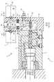
- the single figure shows an electro-proportional control device 1 for a valve 2, which can be used, for example, on a construction machine (wheel loader, excavator, grader or the like).
- the control devices are generally provided in the longitudinal axis of the adjusting piston 3 and act directly on it.
- the adjusting piston 3, which has an extended area 4 is guided within a valve housing 5 and, in this example, controls a main piston 6 hydraulically.
- the control device 1 is formed by two electromagnets 7, 8, only indicated, attached to the valve housing 5, together with magnet armatures 7 ′, 8 ′, which are provided with a predetermined lateral distance from the valve housing 5.
- the center line 9 of the electromagnets 7, 8 runs essentially parallel to the center line 10 of the adjusting piston 3 or the main piston 6.
- the valve housing 5 is connected in the region of its free end 11 to a housing 12, within which a fixed pivot point 13 is provided, which interacts with the housing 12 via connecting elements 14.
- a first lever arm 16 is provided with a length l1.
- a further lever arm 17 is arranged with a length l2.
- a joint 18 is provided in the region of the free end of the lever arm 17 in order to ensure that the rod 15 is deflected without being constrained.
- the lever arms 16, 17 are perpendicular to the center line 19 passing through the pivot point 13. 8 stand and when actuating one or the other electromagnet 7 or 8 prevent an up to 100% going deflection of the adjusting piston 3 and thus the main piston 6 is brought about.
- the spring elements 20, 21 extend in the direction of the corresponding inner walls 22, 23 of the housing 12, where they are guided in corresponding recesses 24, 25.
- F M magnetic force
- F M is consequently smaller with a constant adjusting force F K on the adjusting piston. Since the magnetic force F M is directly proportional to the electrical current, the electrical current consumption is reduced by the ratio l2: l1.
Landscapes
- Engineering & Computer Science (AREA)
- General Engineering & Computer Science (AREA)
- Mechanical Engineering (AREA)
- Physics & Mathematics (AREA)
- Fluid Mechanics (AREA)
- Magnetically Actuated Valves (AREA)
Description
- Die Erfindung betrifft eine elektro-magnetische Steuereinrichtung für Ventile, insbesondere für mobile Arbeitsmaschinen, gemäß gattungsbildendem Teil des ersten Patentanspruches.
- Elektromagnete zur Verstellung von Ventilkolben werden dem allgemeinen St.d.T. entsprechend in axialer Richtung gegen die Stirnfläche des zu verstellenden Kolbens angeordnet, so daß der Kraftfluß vom Magnetanker direkt auf den Verstellkolben erfolgt. Diese Anordnung erfordert einen geringeren mechanischen Aufwand. Die Verstellkräfte sind hierbei genauso groß wie die vom Elektromagneten. Die Kraft vom Elektromagneten ist im wesentlichen nur durch den elektrischen Strom als abhängige Variable beeinflußbar. Die handelsüblichen Elektromagnete verfügen in der Regel über mehr Ankerhub im linearen Bereich ihrer Kennlinie Kraft (F)/elektrischen Strom (I) als für die Auslenkung des Verstellkolbens ausgenutzt wird.
- Die DE-A 29 23 719 zeigt ein gattungsgemäßes magnetbetätigtes 3/2-Wegeventil mit Federrückstellung, insbesondere für den hydraulischen Grubenausbau. Der Ventilkörper des Wegeventils weist hierbei eine Verlängerung auf, wobei auf das Gehäuse des Ventils ein mit Niederspannung eigensicher betriebener Gleichstrommagnet mit einem langhubigen Anker aufgeflanscht ist, der über ein Hebelgetriebe mit der Verlängerung des 3/2-Wegeventils verbunden ist. Eine Schaltverzögerung tritt durch die unmittelbare mechanische Übertragung des Schaltvorganges mittels dieses Hebelgetriebes praktisch nicht auf. Nachteilig ist hier festzustellen, daß infolge der Verwendung eines langhubigen Ankers bei der Krafteinwirkung in dessen ebenfalls lang ausgebildeter Betätigungsstange Verbiegungen auftreten können, die die Führung derselben beeinflussen können. Diese Verbiegung kann sich wiederum nachteilig auf die Kraftübertragung auf den Verstellkolben des Wegeventils auswirken, so daß dessen optimale Funktion ebenfalls in Mitleidenschaft gezogen werden kann.
- Dem Umdruck zur Vorlesung "Grundlagen der Ölhydraulik" (Prof. Dr. Ing. W. Backe), 7. Auflage, 1988 des Institutes für hydraulische und pneumatische Antriebe und Steuerungen der Rheinisch-Westfälischen Technischen Universität Aachen ist auf Seite 7-7 ein Kapitel zum Thema Proportionalwegeventile zu entnehmen. In Bild 7.5 ist ein einstufiges Proportionalwegeventil mit Lageregelung dargestellt, wobei zwei Proportionalmagneten vorgesehen sind, die direkt auf den Steuerschieber einwirken und die Mitteillinien der Betätigungsstangen der Proportionalmagnete identisch mit der Mittellinie des Verstellkolbens des Steuerschiebers sind, d.h. daß eine in Reihe geschaltete Bauweise vorgesehen ist, die keiner Hebelgetriebe, wie sie in der DE-A 29 23 719 angesprochen wurden, bedarf. Nachteil bei dieser Version ist die notwendige Baulänge der gesamten Einheit (Steuerventil mit zwei seitlich angeordneten Proportionalventilen), die insbesondere bei den engen Bauverhältnissen in mobilen Arbeitsmaschinen zu Schwierigkeiten führt. Ohne erhebliche konstruktive Veränderungen vornehmen zu müssen, würde eine Bauform, wie sie die DE-A 29 23 719 vorgibt, übertragen auf die Bauform dieses Dokumentes nicht unbedingt zu einer Reduzierung der Baulänge führen, zumal die Proportionalventile beiderseits des Steuerblocks vorgesehen sind.
- Ziel des Erfindungsgegenstandes ist es, neben einer Reduzierung des Bauaufwandes die Steuereinrichtung dahingehend weiterzubilden, daß der Hub des Magnetankers besser ausgenutzt werden kann und die sich durch niedrigen elektrischen Stromverbrauch bei gleichen Verstellkräften auszeichnet, und deswegen insbesondere für mobile Arbeitsmaschinen mit begrenzter verfügbarer Leistung geeignet sein soll.
- Dieses Ziel wird mit den Maßgaben im kennzeichnenden Teil des ersten Patentanspruches erreicht.
- Vorteilhafte Weiterbildungen des Erfindungsgegenstandes sind den Unteransprüchen zu entnehmen.
- Da die Magnetkraft FM direkt proportional zum elektrischen Strom ist, wird der elektrische Stromverbrauch um das Verhältnis l₂/l₁ reduziert, wobei l₂ der Hebelarm zwischen Verstellkolben und Drehpunkt und l₁ der Hebelarm zwischen Magnetanker und Drehpunkt ist.
- Als Ergebnis wird mit dieser Steuereinrichtung eine elektro-magnetische Verstellung für Ventile erreicht, bei welcher der Hub des jeweiligen Magnetankers besser ausgenutzt werden kann und welche insbesondere dort Anwendung finden kann, wo lediglich begrenzte elektrische Leistungen zum Ansteuern von Ventilen verfügbar sind und demzufolge der geringfügig erhöhte mechanische Mehraufwand gerechtfertigt erscheint.
- Der Erfindungsgegenstand ist anhand eines Ausführungsbeispieles in der Zeichnung dargestellt und wird wie folgt beschrieben.
- Die einzige Figur zeigt eine elektro-proportionale Steuereinrichtung 1 für ein Ventil 2, das beispielsweise an einer Baumaschine (Radlader, Bagger, Grader oder dgl .) Anwendung finden kann. Beim allgemeinen St.d.T. sind die Steuereinrichtungen in der Regel in Achslängsrichtung des Verstellkolbens 3 vorgesehen und wirken unmittelbar auf diesen ein. Der Verstellkolben 3, der einen verlängerten Bereich 4 aufweist, ist innerhalb eines Ventilgehäuses 5 geführt und steuert in diesem Beispiel einen Hauptkolben 6 hydraulisch an. Die Steuereinrichtung 1 wird in diesem Beispiel durch zwei lediglich angedeutete am Ventilgehäuse 5 befestigte Elektromagnete 7,8 samt Magnetankern 7',8' gebildet, die mit vorgegebenem seitlichem Abstand zum Ventilgehäuse 5 vorgesehen sind. Die Mittellinie 9 der Elektromagnete 7,8 verläuft in diesem Beispiel im wesentlichen parallel zur Mittellinie 10 des Verstellkolbens 3 bzw. des Hauptkolbens 6. Andere Anordnungen sind jedoch ebenfalls denkbar. Das Ventilgehäuse 5 ist im Bereich seines freien Endes 11 mit einem Gehäuse 12 verbunden, innerhalb dessen ein fester Drehpunkt 13 vorgesehen ist, der über Verbindungselemente 14 mit dem Gehäuse 12 zusammenwirkt. Zwischen der gemeinsamen Stange 15, der Elektromagnete 7,8 und dem Drehpunkt 13 ist ein erster Hebelarm 16 mit einer Länge l₁ vorgesehen. Zwischen dem Drehpunkt 13 und dem verlängerten Bereich 4 des Verstellkolbens 3 ist ein weiterer Hebelarm 17 mit einer Länge l₂ angeordnet. Im Bereich des freien Endes des Hebelarmes 17 ist ein Gelenk 18 vorgesehen, um einen zwängungsfreien Betrieb bei Auslenkung der Stange 15 zu gewährleisten. In der Nullstellung, d.h. in der nicht ausgelenkten Stellung der Stange 15 stehen die Hebelarme 16,17 senkrecht auf der durch den Drehpunkt 13 gehenden Mittellinie 19. Im Bereich des Hebelarms 15 sind Federelemente 20,21 vorgesehen, die im Kräftegleichgewicht mit den Elektromagneten 7,8 stehen und bei Betätigen des einen oder anderen Elektromagneten 7 bzw. 8 verhindern, daß unmittelbar ein bis zu 100 % gehender Ausschlag des Verstellkolbens 3 und damit des Hauptkolbens 6 herbeigeführt wird. Die Federelemente 20,21 erstrecken sich hierbei in Richtung der korrespondierenden Innenwandungen 22,23 des Gehäuses 12, wo sie in entsprechenden Ausnehmungen 24,25 geführt sind.
- Aufgrund dieser Anordnung ergibt sich die Momentengleichung:


FM = Magnetkraft
FK = Kolbenkraft
l₁ = Hebelarm Magnetanker - Drehpunkt
l₂ = Hebelarm Verstellkolben - Drehpunkt
S₁ = Weg der Magnetanker
S₂ = Weg des Kolbens
Für l₂ kleiner l₁ wird folglich FM kleiner bei konstanter Verstellkraft FK am Verstellkolben. Da die Magnetkraft FM direkt proportional zum elektrischen Strom ist, wird der elektrische Stromverbrauch um das Verhältnis l₂ : l₁ reduziert. - Infolge der vorstehend genannten Parameter ist bei Auslenkung der Magnetanker 7',8' um den Betrag S₁ eine proportionale Auslenkung des Verstellkolbens 3 um den Betrag S₂ gewährleistet. Auch wenn hier ein geringfügig erhöhter mechanischer Aufwand vorgenommen wird, so sind die durch diese Maßnahme erreichten Vorteile, wie z.B. optimale Ausnutzung des Ankerhubes im linearen Bereich der Magnetanker 7',8' in Verbindung mit der Reduzierung des elektrischen Stromverbrauches, dennoch geeignet, für mobile Arbeitsmaschinen mit begrenzter verfügbarer elektrischer Leistung vorteilhaft eingesetzt zu werden.
Claims (5)
- Elektro-magnetische Steuereinrichtung für Ventile, insbesondere für mobile Arbeitsmaschinen, mit einem Ventilgehäuse (5), das mindestens einen Verstellkolben (3) beinhaltet und das mit mindestens einem einen Magnetanker (7',8') aufweisenden Elektromagneten (7,8) zusammenwirkt, wobei- der Elektromagnet (7,8) bzw. der Magnetanker (7',8') mit seitlichem Abstand neben dem Verstellkolben (3) bzw. dem Ventilgehäuse (5) vorgesehen ist und die Mittellinien (9,10) des Verstellkolbens (3) und der Stange (15) des Elektromagneten (7,8) im wesentlichen parallel zueinander verlaufen,- der Magnetanker (7',8') mit dem Verstellkolben (3) über einen im Bereich eines in einem weiteren Gehäuse (12) vorgesehenen Drehpunktes (13) gelagerten Hebels mit unterschiedlich langen Hebelarmen (16,17) verbunden ist und- der längere Hebelarm (16) des Hebels im Bereich der Stange (15) des Elektromagneten (7,8) vorgesehen ist,dadurch gekennzeichnet, daß- zwei Elektromagnete (7,8) samt zugehörigen Magnetankern (7',8') und gemeinsamer Stange (15) seitlich neben dem Verstellkolben (3) bzw. dem Ventilgehäuse (5) vorgesehen sind, wobei das gemeinsame bzw. die einzelnen Gehäuse der Elektromagnete (7,8) fest mit dem Ventilgehäuse (5) verbunden sind,- zumindest eines der freien Enden der Hebelarme (16,17) gegenüber den Elektromagneten (7,8) bzw. dem Verstellkolben (3) gelenkig (18) gelagert ist und- im Bereich eines der Hebelarme (16,17) Federelemente (20,21) vorgesehen sind, die im Kräftegleichgewicht mit den Elektromagneten (7,8) stehen.
- Steuereinrichtung nach Anspruch 1, dadurch gekennzeichnet, daß die Hebelarme (16,17) in ihrer nicht ausgelenkten Stellung im wesentlichen senkrecht auf der durch den Drehpunkt (13) verlaufenden Mittellinie (19) vorgesehen sind.
- Steuereinrichtung nach den Ansprüchen 1 und 2, dadurch gekennzeichnet, daß der Drehpunkt (13) an einer axialen Verlängerung (14) des Gehäuses (12) angeordnet ist.
- Steuereinrichtung nach den Ansprüchen 1 bis 3, dadurch gekennzeichnet, daß die Federelemente (20,21) im Bereich des längeren Hebelarmes (16), sich in Richtung der Innenwandungen (22,23) des Gehäuses (12) erstreckend, angeordnet sind.
- Steuereinrichtung nach den Ansprüchen 1 bis 4, die folgender Momentengleichung genügt:

worin
FM = Magnetkraft
FK = Kolbenkraft
l₁ = Hebelarm Magnetanker - Drehpunkt
l₂ = Hebelarm Verstellkolben - Drehpunkt
sind.
Applications Claiming Priority (2)
| Application Number | Priority Date | Filing Date | Title |
|---|---|---|---|
| DE4142883A DE4142883C2 (de) | 1991-12-23 | 1991-12-23 | Elektro-magnetische Steuereinrichtung für Ventile |
| DE4142883 | 1991-12-23 |
Publications (2)
| Publication Number | Publication Date |
|---|---|
| EP0548466A1 EP0548466A1 (de) | 1993-06-30 |
| EP0548466B1 true EP0548466B1 (de) | 1995-04-12 |
Family
ID=6448072
Family Applications (1)
| Application Number | Title | Priority Date | Filing Date |
|---|---|---|---|
| EP92114952A Expired - Lifetime EP0548466B1 (de) | 1991-12-23 | 1992-09-02 | Elektro-magnetische Steuereinrichtung für Ventile |
Country Status (2)
| Country | Link |
|---|---|
| EP (1) | EP0548466B1 (de) |
| DE (2) | DE4142883C2 (de) |
Family Cites Families (7)
| Publication number | Priority date | Publication date | Assignee | Title |
|---|---|---|---|---|
| FR866238A (fr) * | 1940-03-14 | 1941-07-15 | Perfectionnements aux dispositifs de commande à distance | |
| US2954050A (en) * | 1957-12-23 | 1960-09-27 | Honeywell Regulator Co | Control valve |
| FR2067780A5 (de) * | 1969-11-15 | 1971-08-20 | Applic Mach Motrices | |
| DE2923719A1 (de) * | 1979-06-12 | 1980-12-18 | Aloys Lampferhoff Stahlbau Und | Magnetbetaetigtes 3/2-wegesitzventil mit federrueckstellung, insbesondere fuer den hydraulischen grubenausbau |
| ATE18091T1 (de) * | 1981-09-11 | 1986-03-15 | Heilmeier & Weinlein | Elektrohydraulisches proportionalventil. |
| US4530487A (en) * | 1984-03-16 | 1985-07-23 | Tew Sydney K | Direct drive servovalve and fuel control system incorporating same |
| DE4005501A1 (de) * | 1990-02-21 | 1991-08-22 | Rexroth Mannesmann Gmbh | Steuereinrichtung fuer ein magnetbetaetigtes wegeventil |
-
1991
- 1991-12-23 DE DE4142883A patent/DE4142883C2/de not_active Expired - Fee Related
-
1992
- 1992-09-02 EP EP92114952A patent/EP0548466B1/de not_active Expired - Lifetime
- 1992-09-02 DE DE59201913T patent/DE59201913D1/de not_active Expired - Fee Related
Non-Patent Citations (1)
| Title |
|---|
| W.Backe, GRUNDLAGEN DER ÖLHYDRAULIK, 1988, Institut für Hydraulische und Pneumatische Antriebe und Steuerungen der Rheinisch-Westfälischen Technischen Universität Aachen * |
Also Published As
| Publication number | Publication date |
|---|---|
| DE4142883C2 (de) | 1994-07-28 |
| DE59201913D1 (de) | 1995-05-18 |
| DE4142883A1 (de) | 1993-06-24 |
| EP0548466A1 (de) | 1993-06-30 |
Similar Documents
| Publication | Publication Date | Title |
|---|---|---|
| EP0321890B1 (de) | Handhabungsgerät | |
| DE19655090C2 (de) | Elektromagnetisch betätigtes Wegeventil | |
| DE1802628A1 (de) | Servoventil mit keramischen Leistungsantrieb | |
| DE3307570A1 (de) | Hydraulisches steuersystem fuer eine servoantriebseinheit | |
| DE69623958T2 (de) | Antriebsvorrichtung für einen hydraulischen motor | |
| DE69112740T2 (de) | Vorsteuerventil. | |
| WO2009127349A1 (de) | Steueranordnung zur ansteuerung eines wegeventils | |
| DE3504222A1 (de) | Elektro-hydraulisches servoventil | |
| EP2138720A2 (de) | Verstellvorrichtung für die Verstellung von Axialkolbenmaschinen. | |
| DE10123157C1 (de) | Pneumatikventil | |
| EP0840017A2 (de) | Elektrohydraulische Druckstellvorrichtung und Verfahren zur Umwandlung elektrischer Stellsignale in hydraulischen Stelldruck | |
| DE4032167C1 (en) | Hydraulic actuator position indicator - incorporates cylinder and lines connecting working cylinder to control valve | |
| DE102004014293B4 (de) | Verstelleinheit | |
| EP0548466A1 (de) | Elektro-magnetische Steuereinrichtung für Ventile | |
| DE3243180A1 (de) | Elektromagnetisch betaetigtes wegeventil | |
| DE9116007U1 (de) | Elektro-magnetische Steuereinrichtung für Ventile | |
| DE3800990A1 (de) | Handhabungsgeraet | |
| DE4005501C2 (de) | ||
| DE3938560A1 (de) | Hydraulische steuereinrichtung | |
| DE10033740B4 (de) | Leistungsregeleinrichtung für beidseitige Schwenkrichtung | |
| DE3509399C2 (de) | ||
| DE10337206B4 (de) | Proportional-Hydraulik-Magnetventil | |
| DE3502506A1 (de) | Ventilfernpositionierungseinrichtung | |
| DE3309153A1 (de) | Elektrohydraulisch geregeltes proportionalventil | |
| EP3660335A1 (de) | Schalteinheit und pneumatisches system |
Legal Events
| Date | Code | Title | Description |
|---|---|---|---|
| PUAI | Public reference made under article 153(3) epc to a published international application that has entered the european phase |
Free format text: ORIGINAL CODE: 0009012 |
|
| 17P | Request for examination filed |
Effective date: 19930401 |
|
| AK | Designated contracting states |
Kind code of ref document: A1 Designated state(s): DE FR GB IT SE |
|
| 17Q | First examination report despatched |
Effective date: 19931110 |
|
| GRAA | (expected) grant |
Free format text: ORIGINAL CODE: 0009210 |
|
| ITF | It: translation for a ep patent filed | ||
| AK | Designated contracting states |
Kind code of ref document: B1 Designated state(s): DE FR GB IT SE |
|
| RIN2 | Information on inventor provided after grant (corrected) |
Free format text: PIDDE, GERND * TOLKSDORF, DETLEF |
|
| REF | Corresponds to: |
Ref document number: 59201913 Country of ref document: DE Date of ref document: 19950518 |
|
| ET | Fr: translation filed | ||
| GBT | Gb: translation of ep patent filed (gb section 77(6)(a)/1977) |
Effective date: 19950724 |
|
| ITPR | It: changes in ownership of a european patent |
Owner name: CESSIONE;DETLEF TOLKSDORF |
|
| PLBE | No opposition filed within time limit |
Free format text: ORIGINAL CODE: 0009261 |
|
| REG | Reference to a national code |
Ref country code: GB Ref legal event code: 732E |
|
| 26N | No opposition filed | ||
| REG | Reference to a national code |
Ref country code: FR Ref legal event code: TP |
|
| REG | Reference to a national code |
Ref country code: GB Ref legal event code: IF02 |
|
| PGFP | Annual fee paid to national office [announced via postgrant information from national office to epo] |
Ref country code: GB Payment date: 20030827 Year of fee payment: 12 |
|
| PGFP | Annual fee paid to national office [announced via postgrant information from national office to epo] |
Ref country code: SE Payment date: 20030901 Year of fee payment: 12 |
|
| PGFP | Annual fee paid to national office [announced via postgrant information from national office to epo] |
Ref country code: DE Payment date: 20030903 Year of fee payment: 12 |
|
| PGFP | Annual fee paid to national office [announced via postgrant information from national office to epo] |
Ref country code: FR Payment date: 20030904 Year of fee payment: 12 |
|
| PG25 | Lapsed in a contracting state [announced via postgrant information from national office to epo] |
Ref country code: GB Free format text: LAPSE BECAUSE OF NON-PAYMENT OF DUE FEES Effective date: 20040902 |
|
| PG25 | Lapsed in a contracting state [announced via postgrant information from national office to epo] |
Ref country code: SE Free format text: LAPSE BECAUSE OF NON-PAYMENT OF DUE FEES Effective date: 20040903 |
|
| PG25 | Lapsed in a contracting state [announced via postgrant information from national office to epo] |
Ref country code: DE Free format text: LAPSE BECAUSE OF NON-PAYMENT OF DUE FEES Effective date: 20050401 |
|
| GBPC | Gb: european patent ceased through non-payment of renewal fee |
Effective date: 20040902 |
|
| EUG | Se: european patent has lapsed | ||
| PG25 | Lapsed in a contracting state [announced via postgrant information from national office to epo] |
Ref country code: FR Free format text: LAPSE BECAUSE OF NON-PAYMENT OF DUE FEES Effective date: 20050531 |
|
| REG | Reference to a national code |
Ref country code: FR Ref legal event code: ST |
|
| PG25 | Lapsed in a contracting state [announced via postgrant information from national office to epo] |
Ref country code: IT Free format text: LAPSE BECAUSE OF NON-PAYMENT OF DUE FEES Effective date: 20050902 |