EP0548397B1 - Apparatus for the separation of particles containing solids from a water suspension - Google Patents
Apparatus for the separation of particles containing solids from a water suspension Download PDFInfo
- Publication number
- EP0548397B1 EP0548397B1 EP91122142A EP91122142A EP0548397B1 EP 0548397 B1 EP0548397 B1 EP 0548397B1 EP 91122142 A EP91122142 A EP 91122142A EP 91122142 A EP91122142 A EP 91122142A EP 0548397 B1 EP0548397 B1 EP 0548397B1
- Authority
- EP
- European Patent Office
- Prior art keywords
- suspension
- separator
- filter
- porous
- inlet
- Prior art date
- Legal status (The legal status is an assumption and is not a legal conclusion. Google has not performed a legal analysis and makes no representation as to the accuracy of the status listed.)
- Expired - Lifetime
Links
- 239000007787 solid Substances 0.000 title claims abstract description 18
- 239000002245 particle Substances 0.000 title claims abstract description 17
- 239000007900 aqueous suspension Substances 0.000 title claims abstract description 7
- 238000000926 separation method Methods 0.000 title abstract description 12
- 239000000725 suspension Substances 0.000 claims abstract description 27
- XLYOFNOQVPJJNP-UHFFFAOYSA-N water Substances O XLYOFNOQVPJJNP-UHFFFAOYSA-N 0.000 claims abstract description 24
- 230000005484 gravity Effects 0.000 claims abstract description 11
- 238000004140 cleaning Methods 0.000 claims abstract description 3
- 238000001914 filtration Methods 0.000 claims abstract description 3
- 239000008213 purified water Substances 0.000 claims abstract 2
- 239000011148 porous material Substances 0.000 claims description 4
- 230000007704 transition Effects 0.000 claims description 3
- 230000000694 effects Effects 0.000 abstract description 9
- 238000000034 method Methods 0.000 abstract description 6
- 238000011161 development Methods 0.000 abstract description 2
- 239000003595 mist Substances 0.000 abstract 3
- 239000000853 adhesive Substances 0.000 description 5
- 230000001070 adhesive effect Effects 0.000 description 5
- 230000015572 biosynthetic process Effects 0.000 description 4
- 239000000243 solution Substances 0.000 description 4
- 238000001514 detection method Methods 0.000 description 3
- 239000012071 phase Substances 0.000 description 2
- 238000003825 pressing Methods 0.000 description 2
- 230000001464 adherent effect Effects 0.000 description 1
- 239000008346 aqueous phase Substances 0.000 description 1
- 238000006243 chemical reaction Methods 0.000 description 1
- 238000009795 derivation Methods 0.000 description 1
- 238000013461 design Methods 0.000 description 1
- 238000007373 indentation Methods 0.000 description 1
- 238000012423 maintenance Methods 0.000 description 1
- 239000002184 metal Substances 0.000 description 1
- 230000002093 peripheral effect Effects 0.000 description 1
- 230000010349 pulsation Effects 0.000 description 1
- 230000000717 retained effect Effects 0.000 description 1
- 238000007788 roughening Methods 0.000 description 1
- 238000012216 screening Methods 0.000 description 1
- 238000007873 sieving Methods 0.000 description 1
- 239000007790 solid phase Substances 0.000 description 1
Images

Classifications
-
- B—PERFORMING OPERATIONS; TRANSPORTING
- B01—PHYSICAL OR CHEMICAL PROCESSES OR APPARATUS IN GENERAL
- B01D—SEPARATION
- B01D29/00—Filters with filtering elements stationary during filtration, e.g. pressure or suction filters, not covered by groups B01D24/00 - B01D27/00; Filtering elements therefor
- B01D29/11—Filters with filtering elements stationary during filtration, e.g. pressure or suction filters, not covered by groups B01D24/00 - B01D27/00; Filtering elements therefor with bag, cage, hose, tube, sleeve or like filtering elements
- B01D29/13—Supported filter elements
- B01D29/23—Supported filter elements arranged for outward flow filtration
- B01D29/25—Supported filter elements arranged for outward flow filtration open-ended the arrival of the mixture to be filtered and the discharge of the concentrated mixture are situated on both opposite sides of the filtering element
-
- B—PERFORMING OPERATIONS; TRANSPORTING
- B01—PHYSICAL OR CHEMICAL PROCESSES OR APPARATUS IN GENERAL
- B01D—SEPARATION
- B01D29/00—Filters with filtering elements stationary during filtration, e.g. pressure or suction filters, not covered by groups B01D24/00 - B01D27/00; Filtering elements therefor
- B01D29/50—Filters with filtering elements stationary during filtration, e.g. pressure or suction filters, not covered by groups B01D24/00 - B01D27/00; Filtering elements therefor with multiple filtering elements, characterised by their mutual disposition
- B01D29/56—Filters with filtering elements stationary during filtration, e.g. pressure or suction filters, not covered by groups B01D24/00 - B01D27/00; Filtering elements therefor with multiple filtering elements, characterised by their mutual disposition in series connection
- B01D29/58—Filters with filtering elements stationary during filtration, e.g. pressure or suction filters, not covered by groups B01D24/00 - B01D27/00; Filtering elements therefor with multiple filtering elements, characterised by their mutual disposition in series connection arranged concentrically or coaxially
-
- B—PERFORMING OPERATIONS; TRANSPORTING
- B01—PHYSICAL OR CHEMICAL PROCESSES OR APPARATUS IN GENERAL
- B01D—SEPARATION
- B01D29/00—Filters with filtering elements stationary during filtration, e.g. pressure or suction filters, not covered by groups B01D24/00 - B01D27/00; Filtering elements therefor
- B01D29/88—Filters with filtering elements stationary during filtration, e.g. pressure or suction filters, not covered by groups B01D24/00 - B01D27/00; Filtering elements therefor having feed or discharge devices
- B01D29/90—Filters with filtering elements stationary during filtration, e.g. pressure or suction filters, not covered by groups B01D24/00 - B01D27/00; Filtering elements therefor having feed or discharge devices for feeding
- B01D29/902—Filters with filtering elements stationary during filtration, e.g. pressure or suction filters, not covered by groups B01D24/00 - B01D27/00; Filtering elements therefor having feed or discharge devices for feeding containing fixed liquid displacement elements or cores
-
- B—PERFORMING OPERATIONS; TRANSPORTING
- B01—PHYSICAL OR CHEMICAL PROCESSES OR APPARATUS IN GENERAL
- B01D—SEPARATION
- B01D29/00—Filters with filtering elements stationary during filtration, e.g. pressure or suction filters, not covered by groups B01D24/00 - B01D27/00; Filtering elements therefor
- B01D29/88—Filters with filtering elements stationary during filtration, e.g. pressure or suction filters, not covered by groups B01D24/00 - B01D27/00; Filtering elements therefor having feed or discharge devices
- B01D29/90—Filters with filtering elements stationary during filtration, e.g. pressure or suction filters, not covered by groups B01D24/00 - B01D27/00; Filtering elements therefor having feed or discharge devices for feeding
- B01D29/908—Filters with filtering elements stationary during filtration, e.g. pressure or suction filters, not covered by groups B01D24/00 - B01D27/00; Filtering elements therefor having feed or discharge devices for feeding provoking a tangential stream
Definitions
- the invention relates to a device for separating solid particles from aqueous suspensions by filtration with continuous cleaning of the filter surfaces, the suspension being rotated via an inlet in a plane perpendicular to gravity and under the action of gravity a water curtain is formed which is porous , cylindrical filter surface 6,7 of a separator 1 is guided, along which the aqueous suspension with the solid particles accumulating in the rotating water curtain runs downwards, while the cleaned water passes through the porous filter surface 6,7 and is discharged from there, and the Inlet in front of the separator 1 consists of an inlet nozzle 2 which is essentially tubular.
- a device for separating solid particles from aqueous suspensions of the type mentioned at the outset is known from DE-A-27 08 135.
- a vacuum lock is additionally provided in the known device, which, in conjunction with a vacuum source, ensures that the suspension added forms a closed layer in the separator.
- the known device is designed to be vacuum-tight from the inlet area to the solids discharge.
- a method for rainwater detection from a downpipe coming from the gutter in which the water is passed over a cover part through a conical sieve device and rainwater separation device, the rainwater being divided into one cleaned fraction and into a fraction enriched with dirt particles.
- the division of the rainwater into these fractions is achieved through the use of adhesive separating forces, which derive most of the water from the rainwater separating device.
- the separation takes place in a device consisting of an expanded metal body covering the entire surface of the screen device, the surface of which is increased by roughening.
- Rainwater drainage direction and filter flow direction are in one line.
- the known method according to DE-A-38 12 136 has proven itself in practice, but it is unsuitable for the introduction of rainwater or other suspensions arriving transversely to the flow and filter direction.
- the known device could therefore only be used in some of the rainwater detection devices which lead vertically down from the roof plane and in which there is still enough space to carry out the separation into a device arranged vertically.
- the object of the present invention is to overcome the disadvantages of the rainwater detection devices described above to avoid or separation of solid particles from suspensions and to enable an effective separation of solid particles from horizontally introduced suspensions even at low flow rates without the use of a vacuum.
- the horizontally inflowing suspension is set into a swirl flow beforehand, as a result of which an even more intensive pressing against the side walls of the separator and subsequently of the cylindrical filter surface is achieved.
- the screening device preferably consisting of a double-acting filter element which has an increased formation of adhesive forces.
- the filter element has finely formed capillaries that pull through the sieve body and thus enable solids to be separated.
- the particle size which can be achieved in the separating device according to the invention is below 50 »m.
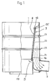
- a separator 1 is shown with a drain port 3. Inside there is a filter element 5, which has a smooth filter outer surface 6 and a roughened filter inner surface 7.
- Baffles ensure that the flow arriving via the inlet connection 2, which is preferably designed as a swirl flow, is converted from a radial / tangential introduction to a predominantly tangential flow, which is applied as a rotational flow to the inside of the surface line.
- the suspension which is set in rotation, is thus pressed against the surface line by means of the guide plates and thus forms a flow thread which, under the action of gravity, changes into a water curtain further down.
- the flow rate of the suspension is further increased by the inlet funnel 12, which forms the transition to the filter element 5.
- the suspension set in a rotating flow is passed as a water curtain over the actual separating surface, which consists of a smooth, internal filter surface 6 and a rough external filter surface 7.
- the solids are filtered out of the suspension up to a size of 100 »m. This is done by pressing the rotationally suspended suspension against smooth, fine-pored filter surfaces 6 under the influence of the peripheral speed, all particles with a diameter of> 100 »being retained, while the cleaned solution runs downwards on the rough filter surface 7.
- the pore channels are alternately opened and closed, so that a pulsation effect in connection with the pressure acting from the smooth filter surface 6 arises. This pressure fluctuation has the effect that any solid particles adhering to the smooth filter surface 6 are detached and removed from the bottom of the separator 1.
- the cleaned solution is discharged from the separator via the outlet nozzle 3.
- the concentrated, solids-containing suspension is disposed of via the main channel 14, further treatment of the suspension optionally being carried out by downstream separation stages which operate according to the method according to the invention.
- the filter element 5 consists of a conical tube, a truncated cone 15 being arranged on the input side and a cone tip 16 being arranged on the output side.
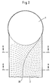
- the swirl flow in the inlet connection 2 can be generated by a depression in the form of a groove 30.
- 2 shows a cross section through the separator 1 at the level of the inlet connector 2 in a basic form, the channel 30 being guided in the flow course from the central axis of the inlet connector 2 to the inner edge of the inlet zone.
- the rainwater flowing in at A-A is thus led to the edge of the separator 1 by a swirling flow.
- FIGS. 2 and 3 show cross sections through the inlet connection 2 at the level of the section lines A-A and B-B.
- the flow channel is displaced by changing the tube sheet 32, so that the inflowing rainwater is led from the left edge of the image to the right edge of the image.
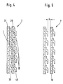
- two layers or more layers of the filter element designed according to the invention can be placed one inside the other. This means that the water flowing through the one filter element enters a new filter element on the outlet side and is deflected there, again due to the adhesive bond.
- the multiple series connection of filter elements thus enables a significant increase in the deflection angle and thus improves the filter effect.
- the water emerging from the separator 1 passes between the knobs 38 via a porous filter layer 37 and from there, in turn, into a second porous layer 39 between the knobs 40. If the distance A between the knobs 38 and the second porous filter layer 39 is increased to 1 to 2 mm, the suction effect or the adhesive forces between the filter elements is improved. This increases the filter effect.
Abstract
Description
Die Erfindung betrifft eine Vorrichtung zur Trennung von Feststoffpartikeln aus wässrigen Suspensionen durch Filtrierung bei fortlaufender Reinigung der Filterflächen, wobei die Suspension über einen Einlauf in einer Ebene senkrecht zur Schwerkraft in Rotation versetzt wird und sich unter Einwirkung der Schwerkraft ein Wasserschleier ausbildet, der über eine poröse, zylindrische Filterfläche 6,7 eines Separators 1 geleitet wird, an der entlang die wässrige Suspension mit den im rotierenden Wasserschleier sich anreichernden Feststoffpartikeln nach unten abläuft, während das gereinigte Wasser durch die poröse Filterfläche 6,7 hindurchtritt und von dort abgeleitet wird und wobei der Einlauf vor dem Separator 1 aus einem Einlaufstutzen 2 besteht, der im wesentlichen rohrförmig ausgebildet ist.The invention relates to a device for separating solid particles from aqueous suspensions by filtration with continuous cleaning of the filter surfaces, the suspension being rotated via an inlet in a plane perpendicular to gravity and under the action of gravity a water curtain is formed which is porous ,
Eine Vorrichtung zur Trennung von Feststoffpartikeln aus wässrigen Suspensionen der eingangs genannten Art ist aus der DE-A-27 08 135 bekannt.A device for separating solid particles from aqueous suspensions of the type mentioned at the outset is known from DE-A-27 08 135.
Für langsame Strömungsgeschwindigkeiten ist bei der bekannten Vorrichtung zusätzlich eine Vakuumschleuse vorgesehen, die in Verbindung mit einer Unterdruckquelle dafür sorgt, daß die aufgegebene Suspension im Separator eine geschlossene Schicht ausbildet. Hierzu ist die bekannte Vorrichtung vom Einlaufbereich bis zum Feststoffabzug vakuumdicht ausgeführt.For slow flow velocities, a vacuum lock is additionally provided in the known device, which, in conjunction with a vacuum source, ensures that the suspension added forms a closed layer in the separator. For this purpose, the known device is designed to be vacuum-tight from the inlet area to the solids discharge.
Gemäß der DE-A-38 12 136 ist ferner ein Verfahren zur Regenwassererfassung aus einem von der Dachrinne abgehenden Fallrohr bekannt, bei dem das Wasser über ein Deckelteil durch eine konische Siebeinrichtung und Regenwassertrenneinrichtung geleitet wird, wobei das Regenwasser aufgeteilt wird, und zwar in eine gereinigte Fraktion und in eine mit Schmutzteilen angereicherte Fraktion.According to DE-A-38 12 136, a method for rainwater detection from a downpipe coming from the gutter is also known, in which the water is passed over a cover part through a conical sieve device and rainwater separation device, the rainwater being divided into one cleaned fraction and into a fraction enriched with dirt particles.
Die Aufteilung des Regenwassers in diese Fraktionen gelingt durch die Nutzung adhäsiver Trennkräfte, die den größten Teil des Wassers aus der Regenwassertrenneinrichtung ableiten. Die Abtrennung geschieht in einer Vorrichtung, bestehend aus einem ganzflächig die Siebeinrichtung abdeckenden Streckmetallkörper, dessen Oberfläche durch Aufrauhen vergrößert ist. Regenwasserabflußrichtung und Filterdurchflußrichtung liegen dabei in einer Linie.The division of the rainwater into these fractions is achieved through the use of adhesive separating forces, which derive most of the water from the rainwater separating device. The separation takes place in a device consisting of an expanded metal body covering the entire surface of the screen device, the surface of which is increased by roughening. Rainwater drainage direction and filter flow direction are in one line.
Das bekannte Verfahren nach DE-A-38 12 136 hat sich in der Praxis bewährt, jedoch ist es für die Einleitung von quer zur Durchfluß- und Filterrichtung ankommendem Regenwasser oder anderen Suspensionen ungeeignet. Die bekannte Vorrichtung konnte daher nur bei einem Teil der Regenwassererfassungseinrichtungen verwendet werden, die senkrecht von der Dachebene herabführen und bei denen noch ausreichend Platz ist, um die Auftrennung in eine senkrecht angeordnete Einrichtung durchzuführen.The known method according to DE-A-38 12 136 has proven itself in practice, but it is unsuitable for the introduction of rainwater or other suspensions arriving transversely to the flow and filter direction. The known device could therefore only be used in some of the rainwater detection devices which lead vertically down from the roof plane and in which there is still enough space to carry out the separation into a device arranged vertically.
Dies ist aber nicht in allen Fällen möglich, da es zunehmend schwierig wird, im äußeren Bereich von größeren Wohnanlagen eine senkrechte Ableitung des Regenwassers durchzuführen. Im übrigen gibt es zahlreiche Anwendungsmöglichkeiten, bei denen Schmutzwasser bzw. Feststoffe enthaltende Suspensionen aus einer horizontalen Leitung austreten. In all diesen Fällen ist eine zufriedenstellend arbeitende Trenneinrichtung bisher nicht bekanntgeworden.However, this is not possible in all cases, since it is becoming increasingly difficult to carry out a vertical drainage of rainwater in the outer area of larger residential complexes. There are also numerous possible applications in which suspensions containing dirty water or solids emerge from a horizontal line. In all of these cases, a satisfactorily operating separating device has so far not become known.
Aufgabe der vorliegenden Erfindung ist es, die Nachteile der eingangs beschriebenen Vorrichtungen zur Regenwassererfassung bzw. Abtrennung von Feststoffpartikeln aus Suspensionen zu vermeiden und eine wirksame Trennung von Feststoffpartikeln aus horizontal eingeleiteten Suspensionen auch bei niedrigen Strömungsgeschwindigkeiten ohne Anwendung eines Vakuums zu ermöglichen.The object of the present invention is to overcome the disadvantages of the rainwater detection devices described above to avoid or separation of solid particles from suspensions and to enable an effective separation of solid particles from horizontally introduced suspensions even at low flow rates without the use of a vacuum.
Erfindungsgemäß wird diese Aufgabe mit den im Patentanspruch 1 angegebenen Merkmalen gelöst.According to the invention this object is achieved with the features specified in
Dabei ist die Einhaltung folgender Maßnahmen wichtig:
- 1. Ausbildung einer in einer Ebene senkrecht zur Schwerkraft rotierenden Suspension.
- 2. Überführung der Rotationsenergie in eine strudelförmige Bewegung.
- 3. Vergrößerung der strudelförmigen Bewegung unter Einwirkung der Schwerkraft und Ausbildung eines Wasserschleiers.
- 4. Ableitung des Wasserschleiers nach unten parallel zu einer porösen, zylindrischen Filterfläche.
- 5. Ableitung der wässrigen Phase aus dem Wasserschleier durch die Poren des zylindrischen Filters und Anreicherung der feststoffhaltigen Phase.
- 6. Ausbildung eines Differenzdruckes zwischen den beide Seiten umfassenden Filterflächen, wobei durch zyklische Veränderungen an den Oberflächen Druckschwankungen auftreten, die zur Entfernung der den Filter sonst verstopfenden Partikel führen.
- 1. Formation of a suspension rotating in a plane perpendicular to gravity.
- 2. Conversion of the rotational energy into a vortex-shaped movement.
- 3. Enlargement of the vortex-shaped movement under the influence of gravity and formation of a water curtain.
- 4. Drainage of the water curtain downwards parallel to a porous, cylindrical filter surface.
- 5. Derivation of the aqueous phase from the water curtain through the pores of the cylindrical filter and enrichment of the solid phase.
- 6. Formation of a differential pressure between the filter surfaces encompassing both sides, with pressure fluctuations occurring due to cyclical changes on the surfaces, which lead to the removal of the particles which otherwise block the filter.
In Weiterbildung des erfindungsgemäßen Gedankens wird die horizontal einströmende Suspension bereits vorher in eine Drallströmung versetzt, wodurch eine noch intensivere Anpressung an die Seitenwände des Separators und nachfolgend der zylindrischen Filterfläche gelingt.In a further development of the idea according to the invention, the horizontally inflowing suspension is set into a swirl flow beforehand, as a result of which an even more intensive pressing against the side walls of the separator and subsequently of the cylindrical filter surface is achieved.
Die erfindungsgemäße Vorrichtung ist im wesentlichen durch folgende Merkmale gekennzeichnet:
- 1. Maßnahmen zur Ausbildung einer Drallströmung im Einlaufstutzen.
- 2. Maßnahmen zur Überführung einer rotierenden Suspension in einen strudelförmigen Partikelstrom. Dies geschieht durch einen schräg angeordneten Einlauftrichter mit einer schneckenförmigen Übergangszone.
- 3. Abtrennung des Feststoffes aus der Suspension in einer Trennzone, wobei die adhäsiven Trennkräfte in einer gegenüber der DE-A-38 12 136 veränderten Siebeinrichtung erzeugt werden.
- 1. Measures to form a swirl flow in the inlet nozzle.
- 2. Measures for converting a rotating suspension into a vortex-shaped particle stream. This is done through an inclined inlet funnel with a helical transition zone.
- 3. Separation of the solid from the suspension in a separation zone, the adhesive separation forces being generated in a sieving device modified compared to DE-A-38 12 136.
Die Trennkräfte werden nunmehr durch Nutzung von Kapillareffekten aufgebracht, wobei die Siebeinrichtung vorzugsweise aus einem doppelt wirksamen Filterelement besteht, das eine verstärkte Ausbildung von Adhäsionskräften aufweist. Das Filterelement hat fein ausgebildete Kapillare, die den Siebkörper durchziehen und somit eine Feststofftrennung ermöglichen. Die erreichbare Teilchengröße liegt bei der erfindungsgemäßen Trenneinrichtung unterhalb von 50 »m.The separating forces are now applied by using capillary effects, the screening device preferably consisting of a double-acting filter element which has an increased formation of adhesive forces. The filter element has finely formed capillaries that pull through the sieve body and thus enable solids to be separated. The particle size which can be achieved in the separating device according to the invention is below 50 »m.
Im folgenden wird die Erfindung anhand eines Ausführungsbeispieles näher erläutert.
- Fig. 1
- zeigt einen Querschnitt durch den Auslauf eines erfindungsgemäßen Separators.
- Fig. 2
- zeigt einen Teilquerschnitt durch einen Einlaufstutzen des erfindungsgemäßen Separators in Draufsicht.
- Fig. 3
- zeigt zwei Querschnitte durch den Einlaufstutzen des erfindungsgemäßen Separators entlang den Schnittlinien A-A und B-B.
- Fig. 4,5
- zeigen zwei Teilquerschnitte durch die poröse Oberfläche des erfindungsgemäßen Separators.
- Fig. 1
- shows a cross section through the outlet of a separator according to the invention.
- Fig. 2
- shows a partial cross section through an inlet port of the separator according to the invention in plan view.
- Fig. 3
- shows two cross sections through the inlet connector of the separator according to the invention along the section lines AA and BB.
- Fig. 4.5
- show two partial cross-sections through the porous surface of the separator according to the invention.
In Figur 1 ist ein Separator 1 mit einem Ablaufstutzen 3 dargestellt. Im Inneren befindet sich ein Filterelement 5, das eine glatte Filteraußenfläche 6 und eine aufgerauhte Filterinnenfläche 7 aufweist.In Figure 1, a
Leitbleche sorgen dafür, daß die über den Einlaufstutzen 2 ankommende Strömung, die vorzugsweise als Drallströmung ausgebildet ist, aus einer radial/tangentialen Einleitung zu einer überwiegend tangentialen Strömung umgeformt wird, die sich als Rotationsströmung an die Innenseite der Mantellinie anlegt. Die in Rotation versetzte Suspension wird also über die Leitbleche an die Mantellinie angedrückt und bildet damit einen Stromfaden aus, der unter Einwirkung der Schwerkraft weiter unten in einen Wasserschleier übergeht.Baffles ensure that the flow arriving via the
Die Strömungsgeschwindigkeit der Suspension wird noch weiter durch den Einlauftrichter 12 erhöht, der die Überleitung zum Filterelement 5 bildet. In diesem Abschnitt des erfindungsgemäßen Separators wird die in Rotationsströmung versetzte Suspension als Wasserschleier über die eigentliche Trennfläche geleitet, die aus einer glatten, innenliegenden Filterfläche 6 und einer rauhen außenliegenden Filterfläche 7 besteht.The flow rate of the suspension is further increased by the
Im Filterelement 5 werden die Feststoffe aus der Suspension bis zu einer Größe von 100 »m herausgefiltert. Dies geschieht dadurch, daß die in Rotation versetzte Suspension unter Einwirkung der Umfangsgeschwindigkeit gegen glatte, feinporige Filterflächen 6 gedrückt wird, wobei alle Partikel mit einem Durchmesser von > 100 » zurückgehalten werden, während die gereinigte Lösung auf der rauhen Filterfläche 7 nach unten abläuft. Beim Ablaufen über die rauhe Filterfläche 7 werden die Porenkanäle abwechselnd geöffnet und geschlossen, so daß in Verbindung mit dem von der glatten Filterfläche 6 her wirkenden Druck eine Pulsationswirkung entsteht. Diese Druckschwankung bewirkt, daß evtl. auf der glatten Filterfläche 6 anhaftende Feststoffpartikel abgelöst und nach unten aus dem Separator 1 entfernt werden.In the
Die gereinigte Lösung wird aus dem Separator über den Auslaufstutzen 3 abgeleitet. Die aufkonzentrierte, feststoffhaltige Suspension wird über den Hauptkanal 14 entsorgt, wobei ggf. eine Weiterbehandlung der Suspension durch nachgeschaltete Trennstufen erfolgt, die nach dem erfindungsgemäßen Verfahren arbeiten.The cleaned solution is discharged from the separator via the
Wie in Figur 1 angedeutet, besteht das Filterelement 5 aus einem kegelförmigen Rohr, wobei an der Eingangsseite ein Kegelstumpf 15 und an der Ausgangsseite eine Kegelspitze 16 angeordnet ist.As indicated in FIG. 1, the
Für das erfindungsgemäße Verfahren ist es wesentlich, daß sich der aus der rotierenden Suspension bildende Wasserschleier möglichst lange innerhalb des Filters aufrecht hält. Neben einer konischen Ausbildung des Filterelementes können hierzu noch weitere Maßnahmen beitragen, die im folgenden vorgestellt werden:
- 1.
Die glatte Filterinnenseite 6 muß möglichst frei von anhaftenden Partikeln gehalten werden. Dies wird durch die bereits erwähnte pulsierende Strömung über die rauhe Filterfläche 7 erreicht. - 2. Durch Ableitung der gereinigten Lösung entsteht ein
Unterdruck im Mantelraum 23 zwischen Filterelement und Separatoraußenwand 24. Durch diesen Unterdruck wird der Wasserschleier durch die Poren angesaugt und bleibt an der glatten Seite der Filterfläche 6 anliegend erhalten. - 3. Ein- bzw. Ausbuchtungen 25 an
der Separatoraußenwand 24 bewirken eine Volumenveränderung und damit eine Druckschwankung, die zusätzlich einen pulsierenden Effekt auf die evtl. auf der glatten Innenseite der Filterfläche 6 anhaftenden ausübt. Diese Maßnahmen unterstützen einzeln und in Kombination die Aufrechterhaltung des Wasserschleiers.
- 1. The smooth inside of the
filter 6 must be kept as free as possible of adhering particles. This is achieved by the already mentioned pulsating flow over therough filter surface 7. - 2. By removing the cleaned solution, a negative pressure is created in the
jacket space 23 between the filter element and the separatorouter wall 24. This negative pressure causes the water curtain to be sucked in through the pores and remains in contact with the smooth side of thefilter surface 6. - 3. Indentations or bulges 25 on the
outer wall 24 of the separator cause a change in volume and thus a pressure fluctuation, which additionally has a pulsating effect on what may be on the smooth inside of thefilter surface 6 adherent exercises. These measures individually and in combination support the maintenance of the water curtain.
Erfindungsgemäß kann die Drallströmung in dem Einlaßstutzen 2 durch eine Vertiefung in Form einer Rinne 30 erzeugt werden. In Figur 2 ist hierzu ein Querschnitt durch den Separator 1 in Höhe des Einlaßstutzens 2 in prinzipieller Form dargestellt, wobei die Rinne 30 im Strömungsverlauf aus der Mittelachse des Einlaßstutzens 2 bis an den Innenrand der Einlaßzone geführt wird. Das bei A-A einfließende Regenwasser wird somit durch eine drallförmige Strömung an den Rand des Separators 1 geführt.According to the invention, the swirl flow in the
In den Figuren 2 und 3 sind Querschnitte durch den Einlaßstutzen 2 in Höhe der Schnittlinien A-A und B-B dargestellt. Man erkennt den äußeren Umfang des Einlaßstutzens 2, der am Rohrboden 31 einen unsymmetrischen Querschnitt in Form einer Strömungsrinne aufweist. Im Vergleich zum Schnitt B-B verlagert sich die Strömungsrinne durch Veränderung des Rohrbodens 32, so daß das einfließende Regenwasser vom linken Bildrand in den rechten Bildrand geführt wird.FIGS. 2 and 3 show cross sections through the
Zur Erhöhung der Sogwirkung des Filterelementes 5 können zwei Schichten oder mehrere Schichten des erfindungsgemäß ausgebildeten Filterelementes ineinandergesetzt werden. Dies bedeutet, daß das durch das eine Filterelement hindurchfließende Wasser auf der Austrittsseite in ein neues Filterelement eintritt und dort, wiederum aufgrund der Adhäsionsbindung, abgelenkt wird. Die mehrfache Hintereinanderschaltung von Filterelementen ermöglicht so eine deutliche Vergrößerung des Ablenkungswinkels und verbessert somit die Filterwirkung.To increase the suction effect of the
Der Vorgang ist in Figur 4 und Figur 5 ausführlich dargestellt.The process is shown in detail in Figure 4 and Figure 5.
Das aus dem Separator 1 austretende Wasser gelangt über eine poröse Filterschicht 37 zwischen die Noppen 38 und von dort wiederum in eine zweite poröse Schicht 39 zwischen die Noppen 40. Bei einer Vergrößerung des Abstandes A zwischen den Noppen 38 und der zweiten porösen Filterschicht 39 auf 1 bis 2 mm verbessert sich die Sogwirkung bzw. die Adhäsionskräfte zwischen den Filterelementen. Dadurch wird die Filterwirkung noch verstärkt.The water emerging from the
Claims (3)
- A device for separating solids-bearing particles from aqueous suspensions by filtering while continuously cleaning the filter faces, with the suspension, by means of an inlet, being made to rotate in a plane which extends perpendicularly to gravity and with a water curtain being formed under the influence of gravity, which water curtain is guided over a porous cylindrical filter face (6, 7) of a separator (1), along which the aqueous suspension together with the solids-bearing particles accumulating in the rotating water curtain is drained off downwardly, whereas the purified water passes through the porous filter face (6, 7) from where it is discharged, and with the inlet in front of the separator (1) consisting of an inlet sleeve (2) which is substantially tubular in shape,
characterised in
that the inlet sleeve (2), at the lower tube base facing the outlet end of the separator (1), comprises a channel (30) which starts from the central axis of the inlet sleeve (2) and extends in the direction of flow as far as the outer edge of the interface between the inlet sleeve (2) and the separator (1), with a narrowing funnel (20) being arranged at the transition between the inlet sleeve (2) and the separator (1); and that the filter face (6, 7) provided with pores or apertures (13) comprises a rough finish on the side facing away from the suspension and a smooth finish on the side facing the suspension. - A device according to claim 1,
characterised in
that the filter face (7) consists of a porous surface (37) with fine capillaries which directly faces the suspension and whose reverse side is provided with nap-shaped raised portions (38) or bevelled portions arranged in the direction of flow. - A device according to any one of the preceding claims,
characterised in
that there is provided a second porous insert (39) which is in contact with the nap-shaped raised portions (38) and which, in turn, on the side facing away, comprises nap-shaped second raised portions (50).
Priority Applications (4)
| Application Number | Priority Date | Filing Date | Title |
|---|---|---|---|
| DE59105200T DE59105200D1 (en) | 1991-12-23 | 1991-12-23 | Device for separating particles containing solids from aqueous suspensions. |
| EP91122142A EP0548397B1 (en) | 1991-12-23 | 1991-12-23 | Apparatus for the separation of particles containing solids from a water suspension |
| AT91122142T ATE120977T1 (en) | 1991-12-23 | 1991-12-23 | DEVICE FOR THE SEPARATION OF PARTICLES CONTAINING SOLIDS FROM AQUEOUS SUSPENSIONS. |
| DK91122142.2T DK0548397T3 (en) | 1991-12-23 | 1991-12-23 | Method and apparatus for separating solids containing particles from aqueous suspensions |
Applications Claiming Priority (1)
| Application Number | Priority Date | Filing Date | Title |
|---|---|---|---|
| EP91122142A EP0548397B1 (en) | 1991-12-23 | 1991-12-23 | Apparatus for the separation of particles containing solids from a water suspension |
Publications (2)
| Publication Number | Publication Date |
|---|---|
| EP0548397A1 EP0548397A1 (en) | 1993-06-30 |
| EP0548397B1 true EP0548397B1 (en) | 1995-04-12 |
Family
ID=8207473
Family Applications (1)
| Application Number | Title | Priority Date | Filing Date |
|---|---|---|---|
| EP91122142A Expired - Lifetime EP0548397B1 (en) | 1991-12-23 | 1991-12-23 | Apparatus for the separation of particles containing solids from a water suspension |
Country Status (4)
| Country | Link |
|---|---|
| EP (1) | EP0548397B1 (en) |
| AT (1) | ATE120977T1 (en) |
| DE (1) | DE59105200D1 (en) |
| DK (1) | DK0548397T3 (en) |
Families Citing this family (8)
| Publication number | Priority date | Publication date | Assignee | Title |
|---|---|---|---|---|
| DE9408254U1 (en) * | 1994-05-19 | 1994-07-28 | Winkler Norbert | Filter device |
| DE29718949U1 (en) * | 1997-09-11 | 1998-01-08 | Hengst Walter Gmbh & Co Kg | Filters, especially rainwater filters |
| DE29716642U1 (en) * | 1997-09-17 | 1997-11-06 | Winkler Norbert | Separating and separating device |
| DE19818427C5 (en) * | 1998-04-24 | 2005-07-07 | Kruk Kunststoffe Gmbh | Filter for use in a device for separating solid particles from aqueous suspensions, in particular from rainwater |
| DE19847655A1 (en) * | 1998-10-15 | 2000-04-20 | Gep Umwelttechnik Gmbh | Cistern filter |
| DE102012017728A1 (en) * | 2012-09-07 | 2014-04-03 | Wisy Ag Haustechniksysteme, Filtertechnik | Water filter, particularly rainwater filter, has sieve with hardening layer that is formed from titanium carbide, titanium nitride, titanium diboride, zirconium carbide, zirconium diboride and niobium carbide |
| DE102012022586A1 (en) * | 2012-11-20 | 2014-05-22 | Wisy Ag Haustechniksysteme, Filtertechnik | Rain water separator for gutter pipe, has cylindrical inlet connection for rain water, which is arranged concentrically to longitudinal axis of screen, where inner wall of inlet connection is provided with helically extending grooves |
| DE102013002013A1 (en) * | 2013-02-06 | 2014-08-07 | Wisy Ag Haustechniksysteme, Filtertechnik | System of components that make up a rainwater separator for a downpipe |
Family Cites Families (5)
| Publication number | Priority date | Publication date | Assignee | Title |
|---|---|---|---|---|
| FI40358B (en) * | 1959-05-05 | 1968-09-02 | Ingersoll Rand World Trade Ltd | |
| DE1245264B (en) * | 1963-02-13 | 1967-07-20 | Starcosa G M B H & Co | Sieve device, consisting of a sieve designed as a downwardly narrowed rotary hollow body with a vertical axis |
| DE2708135A1 (en) * | 1977-02-25 | 1978-08-31 | Schauenburg Masch | Slurries separator for mining operations etc. - comprises basket shaped sieve with cyclonic entry and outer housing to draw=off liquor |
| DE3812136A1 (en) * | 1987-07-21 | 1989-02-02 | Norbert Winkler | Process and apparatus for collecting rainwater |
| DE3835326A1 (en) * | 1988-10-17 | 1990-04-19 | Koller Josef | Apparatus for separating off and collecting solids from a liquid stream |
-
1991
- 1991-12-23 AT AT91122142T patent/ATE120977T1/en not_active IP Right Cessation
- 1991-12-23 DK DK91122142.2T patent/DK0548397T3/en active
- 1991-12-23 EP EP91122142A patent/EP0548397B1/en not_active Expired - Lifetime
- 1991-12-23 DE DE59105200T patent/DE59105200D1/en not_active Expired - Fee Related
Also Published As
| Publication number | Publication date |
|---|---|
| DK0548397T3 (en) | 1995-07-10 |
| EP0548397A1 (en) | 1993-06-30 |
| ATE120977T1 (en) | 1995-04-15 |
| DE59105200D1 (en) | 1995-05-18 |
Similar Documents
| Publication | Publication Date | Title |
|---|---|---|
| EP0548397B1 (en) | Apparatus for the separation of particles containing solids from a water suspension | |
| DE102005014542A1 (en) | Cyclone dust collector and vacuum cleaner with such | |
| DE69816068T2 (en) | DEVICE FOR SEPARATING SOLIDS FROM A LIQUID | |
| CN107050967A (en) | A kind of filter with collecting function | |
| EP0398864B1 (en) | Method and device for the separation of substances from a medium | |
| DE4331415C3 (en) | Method and device for treating a gas stream with washing liquid | |
| DE3523998C2 (en) | ||
| DE102004060981A1 (en) | Dust collecting device for a vacuum cleaner | |
| DE2945951C2 (en) | Method and device for separating materials by means of centrifugal force | |
| DE1544114C3 (en) | Device for separating solid or liquid particles | |
| EP1368132B1 (en) | Coating device for an elongated workpiece | |
| DE2522097A1 (en) | DEVICE FOR SEPARATING SOLID MATERIALS FROM A GAS FLOW | |
| DE19855256A1 (en) | Micro-separator has a spiral flow channel with branch channels to separate a mixture into components with different specific densities without mechanical parts | |
| WO2012038245A1 (en) | Degassing | |
| DE3341281C2 (en) | ||
| DE19807068A1 (en) | Rainwater down-pipe filter | |
| EP3758827A1 (en) | Coalescence separator, in particular for use in a compressed air compressor system, compressed air compressor system, and use of a coalescence separator | |
| DE2645580C2 (en) | Control head for rotary cell filters for industrial use | |
| AT521979B1 (en) | Particle filtering device | |
| DE882543C (en) | Device for separating liquids from vapors and gases by centrifugal force | |
| DE4029611C1 (en) | Dry gas scrubbing system - removes large particles in dry separator and has electrostatic device | |
| DE3537352C2 (en) | ||
| WO2002085493A1 (en) | Filter device | |
| DD295664A5 (en) | METHOD AND DEVICE FOR FILTRATING EXTRACTS FROM PLANT RAW MATERIALS, PREFERABLY SUGAR BEETS | |
| DE2634710A1 (en) | DEVICE FOR REMOVING SOLID AND / OR GAS COMPONENTS FROM A GAS MEDIUM FLOW |
Legal Events
| Date | Code | Title | Description |
|---|---|---|---|
| PUAI | Public reference made under article 153(3) epc to a published international application that has entered the european phase |
Free format text: ORIGINAL CODE: 0009012 |
|
| AK | Designated contracting states |
Kind code of ref document: A1 Designated state(s): AT BE CH DE DK ES FR GB GR IT LI LU MC NL SE |
|
| 17P | Request for examination filed |
Effective date: 19930619 |
|
| RBV | Designated contracting states (corrected) |
Designated state(s): AT BE CH DE DK FR IT LI LU MC |
|
| 17Q | First examination report despatched |
Effective date: 19931229 |
|
| GRAA | (expected) grant |
Free format text: ORIGINAL CODE: 0009210 |
|
| AK | Designated contracting states |
Kind code of ref document: B1 Designated state(s): AT BE CH DE DK FR IT LI LU MC |
|
| REF | Corresponds to: |
Ref document number: 120977 Country of ref document: AT Date of ref document: 19950415 Kind code of ref document: T |
|
| REF | Corresponds to: |
Ref document number: 59105200 Country of ref document: DE Date of ref document: 19950518 |
|
| ITF | It: translation for a ep patent filed |
Owner name: JACOBACCI & PERANI S.P.A. |
|
| REG | Reference to a national code |
Ref country code: DK Ref legal event code: T3 |
|
| ET | Fr: translation filed | ||
| PLBE | No opposition filed within time limit |
Free format text: ORIGINAL CODE: 0009261 |
|
| STAA | Information on the status of an ep patent application or granted ep patent |
Free format text: STATUS: NO OPPOSITION FILED WITHIN TIME LIMIT |
|
| 26N | No opposition filed | ||
| PGFP | Annual fee paid to national office [announced via postgrant information from national office to epo] |
Ref country code: MC Payment date: 19971223 Year of fee payment: 7 |
|
| PG25 | Lapsed in a contracting state [announced via postgrant information from national office to epo] |
Ref country code: MC Free format text: LAPSE BECAUSE OF NON-PAYMENT OF DUE FEES Effective date: 19990630 |
|
| PGFP | Annual fee paid to national office [announced via postgrant information from national office to epo] |
Ref country code: FR Payment date: 20001128 Year of fee payment: 10 Ref country code: DK Payment date: 20001128 Year of fee payment: 10 |
|
| PGFP | Annual fee paid to national office [announced via postgrant information from national office to epo] |
Ref country code: AT Payment date: 20001214 Year of fee payment: 10 |
|
| PGFP | Annual fee paid to national office [announced via postgrant information from national office to epo] |
Ref country code: CH Payment date: 20001221 Year of fee payment: 10 |
|
| PGFP | Annual fee paid to national office [announced via postgrant information from national office to epo] |
Ref country code: LU Payment date: 20010102 Year of fee payment: 10 |
|
| PGFP | Annual fee paid to national office [announced via postgrant information from national office to epo] |
Ref country code: BE Payment date: 20010103 Year of fee payment: 10 |
|
| PGFP | Annual fee paid to national office [announced via postgrant information from national office to epo] |
Ref country code: DE Payment date: 20010226 Year of fee payment: 10 |
|
| PG25 | Lapsed in a contracting state [announced via postgrant information from national office to epo] |
Ref country code: LU Free format text: LAPSE BECAUSE OF NON-PAYMENT OF DUE FEES Effective date: 20011223 Ref country code: DK Free format text: LAPSE BECAUSE OF NON-PAYMENT OF DUE FEES Effective date: 20011223 Ref country code: AT Free format text: LAPSE BECAUSE OF NON-PAYMENT OF DUE FEES Effective date: 20011223 |
|
| PG25 | Lapsed in a contracting state [announced via postgrant information from national office to epo] |
Ref country code: LI Free format text: LAPSE BECAUSE OF NON-PAYMENT OF DUE FEES Effective date: 20011231 Ref country code: CH Free format text: LAPSE BECAUSE OF NON-PAYMENT OF DUE FEES Effective date: 20011231 Ref country code: BE Free format text: LAPSE BECAUSE OF NON-PAYMENT OF DUE FEES Effective date: 20011231 |
|
| BERE | Be: lapsed |
Owner name: WINKLER NORBERT Effective date: 20011231 |
|
| PG25 | Lapsed in a contracting state [announced via postgrant information from national office to epo] |
Ref country code: DE Free format text: LAPSE BECAUSE OF NON-PAYMENT OF DUE FEES Effective date: 20020702 |
|
| REG | Reference to a national code |
Ref country code: CH Ref legal event code: PL |
|
| PG25 | Lapsed in a contracting state [announced via postgrant information from national office to epo] |
Ref country code: FR Free format text: LAPSE BECAUSE OF NON-PAYMENT OF DUE FEES Effective date: 20020830 |
|
| REG | Reference to a national code |
Ref country code: DK Ref legal event code: EBP |
|
| REG | Reference to a national code |
Ref country code: FR Ref legal event code: ST |
|
| PG25 | Lapsed in a contracting state [announced via postgrant information from national office to epo] |
Ref country code: IT Free format text: LAPSE BECAUSE OF NON-PAYMENT OF DUE FEES;WARNING: LAPSES OF ITALIAN PATENTS WITH EFFECTIVE DATE BEFORE 2007 MAY HAVE OCCURRED AT ANY TIME BEFORE 2007. THE CORRECT EFFECTIVE DATE MAY BE DIFFERENT FROM THE ONE RECORDED. Effective date: 20051223 |