EP0547713A1 - Suction system for ring spinning machines - Google Patents
Suction system for ring spinning machines Download PDFInfo
- Publication number
- EP0547713A1 EP0547713A1 EP92203959A EP92203959A EP0547713A1 EP 0547713 A1 EP0547713 A1 EP 0547713A1 EP 92203959 A EP92203959 A EP 92203959A EP 92203959 A EP92203959 A EP 92203959A EP 0547713 A1 EP0547713 A1 EP 0547713A1
- Authority
- EP
- European Patent Office
- Prior art keywords
- spinning machine
- spinning
- suction system
- suction
- floor
- Prior art date
- Legal status (The legal status is an assumption and is not a legal conclusion. Google has not performed a legal analysis and makes no representation as to the accuracy of the status listed.)
- Withdrawn
Links
Images

Classifications
-
- D—TEXTILES; PAPER
- D01—NATURAL OR MAN-MADE THREADS OR FIBRES; SPINNING
- D01H—SPINNING OR TWISTING
- D01H11/00—Arrangements for confining or removing dust, fly or the like
- D01H11/005—Arrangements for confining or removing dust, fly or the like with blowing and/or suction devices
Definitions
- This invention relates to a suction system for ring spinning machines, the system being arranged to remove trash, fibre fluff and broken threads from the space surrounding the spinning faces.
- Said ring spinning machines normally comprise a plurality of working positions on two opposing faces, and are therefore very long.
- Textile machines comprise suction ducts for the most varied purposes, for example to clean determined parts of the machine, to remove fibre trash and to draw off excessive yarn ends or pieces of cut yarn or the like. It is well known that in drafting systems of spinning machines, a fibre bundle consisting of an assembly of fibres of varying lengths is subjected to considerable traction stresses resulting in separation of a certain quantity of in particular short fibres and the formation of trash. It is therefore necessary to clean the drafting members and remove the flying fibrillae and fibres and the trash from the various machine parts and from the yarn under formation. It is also necessary to draw off and remove any pieces of broken yarn.
- the suction action has to be effective and uniform along the entire spinning face.
- the spinning faces of ring spinning machines are of considerable horizontal extension of some tens of metres, as the spinning spindles can be present in a quantity of the order of a thousand, one following the other.
- the cross-sectional area of the air suction duct and the power of the pneumatic system therefore become relatively large, with consequent high system and operating costs.
- the continuous draw-off of trash, fibres and broken threads in known systems is insufficient in those regions farthest from the motor-driven suction fan or other type of suction device which provides the suction action.
- the air throughput in a central suction system, in which a suction duct extends along the entire spinning face to serve all the spinning spindles via suction nozzles or slits is represented by the total air quantity necessary in order to achieve an energetic suction action at the spinning spindles.
- Fibres, dust and broken threads which have not been properly drawn off from the suction tubes often trigger their clogging, so blocking the suction action required for continuous cleaning of the spindles, which are hence subjected to progressive deposition of fibre trash on their various parts and on the yarn under formation. This results in yarn irregularities and defects which reduce its quality, such irregularities leading in the limit to yarn breakage during the formation stage or during subsequent yarn processing stages.
- An object of the present invention is to provide a suction system for removing fibre trash and broken fibre pieces in spinning machines which is free of the aforesaid drawbacks and is able to perform its function with greater effectiveness and for a longer time, without requiring frequent maintenance.
- a further object of the present invention is to rationalize the construction of the suction system of a ring spinning machine, both in terms of its capacity and of its suction efficiency in effectively removing fibrils and floating yarn pieces from the suction spindles.
- a further object of the present invention is to provide a pneumatic suction system of new while at the same time simple concept, which makes it possible to put under suction several regions which integrate and complete the entire suction operation with further functions required for the particular application underway.
- suction system of the present invention arranged on a spinning machine of considerable longitudinal extension, in particular a ring spinning machine, wherein said suction system comprises, along the entire length of the spinning machine, internal walls which converge in the direction of a mouth at the floor-level opening of ducting put under vacuum by the central suction system of the factory, said converging internal walls being sufficiently raised from the level of the floor on which the spinning machine rests, to allow energetic lateral draw-in of the air surrounding the spinning machine.
- Figure 1 is a schematic sectional view perpendicular to the longitudinal axis of the spinning machine, showing the upper manifold channel which operates in cleaning the drafting rollers, and the profile of the internal walls which converge in the direction of a mouth at the floor-level opening of ducting put under vacuum by the central suction system of the factory.
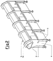
- Figure 2 is a front isometric schematic view of a longitudinal portion of the ring spinning machine suction system of the present invention.
- the suction fan which puts the channel 2 under vacuum and the filter elements (not shown) are positioned at the end of the spinning machine 10.
- the fibre trash and the dust present around the drafting unit 15 are drawn off by the slit in the tube 14 and conveyed into the manifold channel 2 which conveys them within its air stream to the end of the spinning machine 10 where they are retained by the filter surfaces. Simultaneously during the spinning process, the fibre trash, dust and broken yarn pieces present in proximity to the spinning spindle 11 are conveyed into the air stream 9, which conveys them together with the fibre trash of the air stream 7 into the ducting 6 of the factory suction system.
Abstract
A suction system for textile machines, in particular for ring spinning machines, comprising an upper manifold channel (2) operating in cleaning the spinning machine drafting rollers (15), and also comprising, along the entire length of the spinning machine, internal walls (1,3) which converge in the direction of floor-level ducting (6) put under vacuum by the central suction system of the factory, said converging internal walls (1,3) being sufficiently raised from the level of the floor (8) on which the spinning machine rests, to allow energetic lateral draw-in of the air surrounding the spinning machine.
Description
- This invention relates to a suction system for ring spinning machines, the system being arranged to remove trash, fibre fluff and broken threads from the space surrounding the spinning faces. Said ring spinning machines normally comprise a plurality of working positions on two opposing faces, and are therefore very long.
- Textile machines comprise suction ducts for the most varied purposes, for example to clean determined parts of the machine, to remove fibre trash and to draw off excessive yarn ends or pieces of cut yarn or the like. It is well known that in drafting systems of spinning machines, a fibre bundle consisting of an assembly of fibres of varying lengths is subjected to considerable traction stresses resulting in separation of a certain quantity of in particular short fibres and the formation of trash. It is therefore necessary to clean the drafting members and remove the flying fibrillae and fibres and the trash from the various machine parts and from the yarn under formation. It is also necessary to draw off and remove any pieces of broken yarn.
- In this case the suction action has to be effective and uniform along the entire spinning face. In addition, the spinning faces of ring spinning machines are of considerable horizontal extension of some tens of metres, as the spinning spindles can be present in a quantity of the order of a thousand, one following the other.
- The cross-sectional area of the air suction duct and the power of the pneumatic system therefore become relatively large, with consequent high system and operating costs. In addition, because of the considerable length of ring spinning machines, the continuous draw-off of trash, fibres and broken threads in known systems is insufficient in those regions farthest from the motor-driven suction fan or other type of suction device which provides the suction action. The air throughput in a central suction system, in which a suction duct extends along the entire spinning face to serve all the spinning spindles via suction nozzles or slits, is represented by the total air quantity necessary in order to achieve an energetic suction action at the spinning spindles.
- Problems occur in known constructions, such as the retention of a certain number of broken fibres and threads in the suction tubes acting on the spinning spindles in those regions farthest from the fan in the machine headstock.
- Fibres, dust and broken threads which have not been properly drawn off from the suction tubes often trigger their clogging, so blocking the suction action required for continuous cleaning of the spindles, which are hence subjected to progressive deposition of fibre trash on their various parts and on the yarn under formation. This results in yarn irregularities and defects which reduce its quality, such irregularities leading in the limit to yarn breakage during the formation stage or during subsequent yarn processing stages.
- The maintenance and cleaning of the suction slits requires considerable attention by the service personnel, who are required to work without any established timetable. It is understandable that work carried out on a selective or random basis without an established timetable leads to low labour efficiency.
- An object of the present invention is to provide a suction system for removing fibre trash and broken fibre pieces in spinning machines which is free of the aforesaid drawbacks and is able to perform its function with greater effectiveness and for a longer time, without requiring frequent maintenance.
- A further object of the present invention is to rationalize the construction of the suction system of a ring spinning machine, both in terms of its capacity and of its suction efficiency in effectively removing fibrils and floating yarn pieces from the suction spindles.
- A further object of the present invention is to provide a pneumatic suction system of new while at the same time simple concept, which makes it possible to put under suction several regions which integrate and complete the entire suction operation with further functions required for the particular application underway.
- These and further objects of the invention, which will be more apparent during the course of the description, are attained by the suction system of the present invention arranged on a spinning machine of considerable longitudinal extension, in particular a ring spinning machine, wherein said suction system comprises, along the entire length of the spinning machine, internal walls which converge in the direction of a mouth at the floor-level opening of ducting put under vacuum by the central suction system of the factory, said converging internal walls being sufficiently raised from the level of the floor on which the spinning machine rests, to allow energetic lateral draw-in of the air surrounding the spinning machine.
- One embodiment of the invention is described in detail and further clarified hereinafter by way of non-limiting example with reference to the figures of the accompanying drawing.
- Figure 1 is a schematic sectional view perpendicular to the longitudinal axis of the spinning machine, showing the upper manifold channel which operates in cleaning the drafting rollers, and the profile of the internal walls which converge in the direction of a mouth at the floor-level opening of ducting put under vacuum by the central suction system of the factory.
- Figure 2 is a front isometric schematic view of a longitudinal portion of the ring spinning machine suction system of the present invention.
- In the figures, corresponding parts or parts with identical functions carry identical reference characters for simplicity.
- The various units and the equipment which operate in forming the yarn in the ring spinning machine, into which the suction system of the present invention is incorporated, are neither illustrated nor is their operation described, as they are already known and do not concern the operation of the present invention.
- In the accompanying drawings:
- 10 schematically represents the ring spinning machine, which during spinning operates on two opposing faces with a large plurality of working positions, and is hence of considerable longitudinal extension;
- 2 is the upper suction manifold channel of
box structure 5, put under vacuum by a motor-driven fan (not shown) positioned at one end of thespinning machine 10. Said manifoldchannel 2 is arranged to apply suction action for cleaning thedrafting units 15 viatubes 14; - 1 and 3 are the walls internal to the
spinning machine 10, said internal walls defining aspace 4 converging in the direction of a mouth at the opening in thefloor 8 of ducting 6 put under vacuum by the central suction system (not shown) of the factory; - 9 are arrows indicating the direction of the air stream which provides energetic suction in proximity to the known
spinning spindles 11 andring carrying benches 12; - 7 are arrows indicating the direction of the air stream below the spinning machine, said
stream 7 being drawn in by the suction present in theducting 6. - The operation of the suction system of the present invention shown in the figure of the accompanying drawings is easily deduced.
- The suction fan which puts the
channel 2 under vacuum and the filter elements (not shown) are positioned at the end of thespinning machine 10. - The fibre trash and the dust present around the
drafting unit 15 are drawn off by the slit in thetube 14 and conveyed into themanifold channel 2 which conveys them within its air stream to the end of thespinning machine 10 where they are retained by the filter surfaces. Simultaneously during the spinning process, the fibre trash, dust and broken yarn pieces present in proximity to the spinningspindle 11 are conveyed into theair stream 9, which conveys them together with the fibre trash of theair stream 7 into theducting 6 of the factory suction system. - Modifications in terms of detail can be made to the suction system of the present invention, but without leaving the scope of the invention.
Claims (1)
- A suction system for ring spinning machines, comprising an upper manifold channel extending along the entire spinning face and operating in cleaning the drafting rollers, characterised by comprising, along the entire length of the spinning machine, internal walls which converge in the direction of a mouth at the floor-level opening of ducting put under vacuum by the central suction system of the factory, said converging internal walls being sufficiently raised from the level of the floor on which the spinning machine rests, to allow energetic lateral draw-in of the air surrounding the spinning machine.
Applications Claiming Priority (2)
| Application Number | Priority Date | Filing Date | Title |
|---|---|---|---|
| ITMI913418A IT1252554B (en) | 1991-12-19 | 1991-12-19 | VACUUM SYSTEM FOR RING SPINNING MACHINES |
| ITMI913418 | 1991-12-19 |
Publications (1)
| Publication Number | Publication Date |
|---|---|
| EP0547713A1 true EP0547713A1 (en) | 1993-06-23 |
Family
ID=11361384
Family Applications (1)
| Application Number | Title | Priority Date | Filing Date |
|---|---|---|---|
| EP92203959A Withdrawn EP0547713A1 (en) | 1991-12-19 | 1992-12-16 | Suction system for ring spinning machines |
Country Status (2)
| Country | Link |
|---|---|
| EP (1) | EP0547713A1 (en) |
| IT (1) | IT1252554B (en) |
Citations (5)
| Publication number | Priority date | Publication date | Assignee | Title |
|---|---|---|---|---|
| DE2903139A1 (en) * | 1979-01-27 | 1980-08-07 | Schlafhorst & Co W | METHOD AND DEVICE FOR PREVENTING THE DELIVERY OF DUST AND FIBER PARTS FROM THE WORKING ZONES OF A TEXTILE MACHINE |
| JPS6262935A (en) * | 1985-09-13 | 1987-03-19 | Nisshinbo Ind Inc | Cleaning apparatus for fine spinning frame |
| DE8908921U1 (en) * | 1989-07-22 | 1989-11-02 | Zinser Textilmaschinen Gmbh, 7333 Ebersbach, De | |
| EP0395591A1 (en) * | 1989-04-25 | 1990-10-31 | Howa Machinery, Ltd. | An apparatus for cleaning a spinning frame |
| EP0487120A1 (en) * | 1990-10-23 | 1992-05-27 | SAVIO S.p.A. | Improvements in spinning machines with suction provided by a works central suction system |
-
1991
- 1991-12-19 IT ITMI913418A patent/IT1252554B/en active IP Right Grant
-
1992
- 1992-12-16 EP EP92203959A patent/EP0547713A1/en not_active Withdrawn
Patent Citations (5)
| Publication number | Priority date | Publication date | Assignee | Title |
|---|---|---|---|---|
| DE2903139A1 (en) * | 1979-01-27 | 1980-08-07 | Schlafhorst & Co W | METHOD AND DEVICE FOR PREVENTING THE DELIVERY OF DUST AND FIBER PARTS FROM THE WORKING ZONES OF A TEXTILE MACHINE |
| JPS6262935A (en) * | 1985-09-13 | 1987-03-19 | Nisshinbo Ind Inc | Cleaning apparatus for fine spinning frame |
| EP0395591A1 (en) * | 1989-04-25 | 1990-10-31 | Howa Machinery, Ltd. | An apparatus for cleaning a spinning frame |
| DE8908921U1 (en) * | 1989-07-22 | 1989-11-02 | Zinser Textilmaschinen Gmbh, 7333 Ebersbach, De | |
| EP0487120A1 (en) * | 1990-10-23 | 1992-05-27 | SAVIO S.p.A. | Improvements in spinning machines with suction provided by a works central suction system |
Non-Patent Citations (1)
| Title |
|---|
| PATENT ABSTRACTS OF JAPAN vol. 011, no. 262 (C-442)(2709) 25 August 1987 & JP-A-62 062 935 ( NISSHINBO IND ) 19 March 1987 * |
Also Published As
| Publication number | Publication date |
|---|---|
| IT1252554B (en) | 1995-06-19 |
| ITMI913418A1 (en) | 1993-06-19 |
| ITMI913418A0 (en) | 1991-12-19 |
Similar Documents
| Publication | Publication Date | Title |
|---|---|---|
| US2977181A (en) | Suction cleaning system for textile machinery | |
| US4773208A (en) | Thread or roving fragment removal for a spinning machine | |
| US3834145A (en) | Open-end spinning of textile yarns | |
| US6221121B1 (en) | Filter apparatus for a textile machine having relief and collector elements | |
| EP2045378A1 (en) | Dust collecting and processing system in textile machine | |
| US5279629A (en) | Air handling apparatus and method for textile machines | |
| ES454974A1 (en) | Method and apparatus for pneumatically removing fiber and trash waste on open-end spinning machines | |
| US3429745A (en) | Method of removing fiber waste from spinning frames | |
| US2946174A (en) | Apparatus for doffing lint collection chambers | |
| US2717484A (en) | Cleaning device for thread working textile machines | |
| EP0547713A1 (en) | Suction system for ring spinning machines | |
| EP0546644A1 (en) | Suction system for textile machinery and in particular for a ring spinning machine | |
| US3782095A (en) | Method and arrangement for withdrawing air from spinning units | |
| CN106435871A (en) | Cleaning type drawing frame | |
| EP0487119A1 (en) | Improvements in spinning machines with a suction system for capturing and removing dust, fibre web and broken yarns | |
| EP0487120A1 (en) | Improvements in spinning machines with suction provided by a works central suction system | |
| US3251100A (en) | Drafting system with top and bottom roll cleaning | |
| EP0168944B1 (en) | Dust extractor for drawframe | |
| US3999250A (en) | Method of fiber distribution and ribbon forming | |
| EP0484997A1 (en) | Improvement in spinning machines with a pneumatic suction system for removing dust, fibre web and broken yarns | |
| EP0482710A1 (en) | Improvements in spinning machines with a suction system for removing dust, fibre web and broken yarns | |
| EP0482711A1 (en) | Improvements in spinning machines with a suction system for removing dust, fibre web and broken yarns | |
| CN1061392C (en) | Method of cleaning the rotor of a rotor spinning machine and device for carrying out the method | |
| JPS5818424A (en) | Method and apparatus for sucking yarn trash when yarn is cut | |
| DE4131525A1 (en) | Bobbin winder assembly cleaner - has common under pressure channel to remove dust from walls and winders while usable fibres are retained |
Legal Events
| Date | Code | Title | Description |
|---|---|---|---|
| PUAI | Public reference made under article 153(3) epc to a published international application that has entered the european phase |
Free format text: ORIGINAL CODE: 0009012 |
|
| AK | Designated contracting states |
Kind code of ref document: A1 Designated state(s): AT BE CH DE DK ES FR GB GR IE LI LU MC NL PT SE |
|
| STAA | Information on the status of an ep patent application or granted ep patent |
Free format text: STATUS: THE APPLICATION IS DEEMED TO BE WITHDRAWN |
|
| 18D | Application deemed to be withdrawn |
Effective date: 19931224 |