EP0546772A1 - Münzverpackungsvorrichtung - Google Patents
Münzverpackungsvorrichtung Download PDFInfo
- Publication number
- EP0546772A1 EP0546772A1 EP92311081A EP92311081A EP0546772A1 EP 0546772 A1 EP0546772 A1 EP 0546772A1 EP 92311081 A EP92311081 A EP 92311081A EP 92311081 A EP92311081 A EP 92311081A EP 0546772 A1 EP0546772 A1 EP 0546772A1
- Authority
- EP
- European Patent Office
- Prior art keywords
- coin
- passage
- coins
- information
- unit
- Prior art date
- Legal status (The legal status is an assumption and is not a legal conclusion. Google has not performed a legal analysis and makes no representation as to the accuracy of the status listed.)
- Granted
Links
Images


Classifications
-
- G—PHYSICS
- G07—CHECKING-DEVICES
- G07D—HANDLING OF COINS OR VALUABLE PAPERS, e.g. TESTING, SORTING BY DENOMINATIONS, COUNTING, DISPENSING, CHANGING OR DEPOSITING
- G07D9/00—Counting coins; Handling of coins not provided for in the other groups of this subclass
- G07D9/06—Devices for stacking or otherwise arranging coins on a support, e.g. apertured plate for use in counting coins
- G07D9/065—Devices for wrapping coins
Definitions
- the present invention relates to coin packaging apparatus, and more particularly to coin packaging apparatus which automatically adjust the inner diameter of a coin stacking portion and a height and width of a coin passage and performs processing for the type and amount of coins.
- the coin packaging apparatus disclosed in this publication feeds coins one by one from a circular plate and conveys them along a coin passage in which processing such as totaling and stopping of the coins to be packaged is performed for small-diameter coins, and the coins are then fed to a coin stacking portion provided at the end of the coin passage and are successively stacked. When a required number of coins has been stacked, those stacked coins are sent to a packaging portion and are packaged in paper packaging.
- the coin passage comprises a thickness regulating member which regulates the coins fed from the circular plate to a single layer, and a conveyor belt which contacts the upper surface of the coins and conveys them, with both the thickness regulating member and the conveyor belt being supported in a movable frame which can move up and down, and the manual rotation of a height adjustment handle moves the entire frame up and down and adjusts the height of the coin passage.
- the coin packaging portion has three packaging rollers which sandwich the stacked coins by approaching the coins while rotating, and packaging paper is fed between the rollers and the stacked coins and is wound around the stacked coins and the top and bottom ends of the packaging paper are bent inwards by a folding head.
- the cam which adjusts the inner diameter of the coin stacking portion and the width of the coin passage is formed in a multi-sided shape which corresponds to several types of coin which are the object of processing and so when a coin packaging machine is exported to another country for example, there is the problem that a cam which corresponds to the currency of the country which is the destination of export has to be specially incorporated into the coin packaging apparatus, thereby preventing the mass production of coin packaging apparatus.
- the present invention is a coin packaging apparatus which feeds coins one by one from a circular plate and conveys them along a coin passage in which processing such as totaling and stopping of the coins to be packaged is performed for small-diameter coins. And the coins are then fed to a coin stacking portion provided at the end of the coin passage and are successively stacked and when a required number of coins has been stacked. Those stacked coins are sent to a packaging portion and are packaged in paper packaging.
- This coin packaging apparatus of the present invention is characterized in being provided with a coin passage width adjustment means which steplessly adjusts a passage width of the coin passage, a coin passage height adjustment means which steplessly adjusts a passage height of the coin passage, a coin stacking portion inner diameter adjustment means which steplessly adjusts an inner diameter of the coin stacking portion, a coin information storage means which stores coin information of at least a diameter and a thickness of coins to be processed and in correspondence with a type of coin, a coin type specification means which specifies a type of coin to be processed, and a control portion which determines an inner diameter of a coin stacking portion and a height and a width of a coin passage portion from coin information of said coin information storage means and on the basis of a coin type specification of the coin type specification means, and operates each of said adjustment means to those determined dimensions.
- the present invention has the configuration described above and which is further provided with a coin information input means for the input of coin information which is information including at least a thickness and a diameter of a coin to be processed coin information, the coin information storage means which stores the coin information input by the coin information input means and so as to correspond to a coin type, the coin type specification means which specifies a coin type of coins to be processed, and a calculation means which uses the coin information to calculate an inner diameter of a coin stacking portion and a height and width of a coin passage suited for processing of the coin type, and the control portion which uses specifications by the coin type specification mechanism as the basis for operating each of the adjustment mechanisms so that there is agreement with calculation results of the calculation means.
- a coin information input means for the input of coin information which is information including at least a thickness and a diameter of a coin to be processed coin information
- the coin information storage means which stores the coin information input by the coin information input means and so as to correspond to a coin type
- the coin type specification means which specifies a coin type of coins
- the control of the control portion when there is the specification of a coin type by a coin type specification means, the control of the control portion reads the coin information for that specified coin type from the coin type information storage means, and determines an inner diameter of a coin stacking portion and a width and height of a coin passage so that they are suited to the diameter and thickness, and a control portion operates the coin passage width adjustment means, the coin passage height adjustment means and the coin stacking portion inner diameter adjustment means are steplessly adjusted, so that their dimensions are adjusted be in agreement with the to the respective specified coin types.
- the coin type specification means specifies a coin type
- the coin information for coins of the type and which is input beforehand to the coin information storage means by the coin information input means is used as the basis for the calculation means to calculate the inner diameter of the coin stacking portion and the width and height of the coin passage
- the control portion operates the coin passage width adjustment means, the coin passage height adjustment means, and the coin stacking portion inner diameter adjustment means so that inner diameter of the coin stacking portion and the width and height of the coin passage are made to agree with the calculated values.
- the coin type specification means specifies a coin type
- the coin information for coins of the type and which is input beforehand to the coin information storage means by the coin information input means is used as the basis for the calculation means to calculate the inner diameter of the coin stacking portion and the width and height of the coin passage
- the control portion operates the coin passage width adjustment means, the coin passage height adjustment means, the coin stacking portion inner diameter adjustment means and the fine adjustment means so that inner diameter of the coin stacking portion and the width and height of the coin passage are made to agree with the calculated values.
- a coin packaging apparatus 1 is provided with a rotating plate 4 which receives and supplies coins from inside a coin insertion hopper 3 which opens to the top of a machine unit 2, and a rotating plate 5 which receives coins supplied from the rotating plate 4, both plates being freely rotatable, and opposite the rotating plate 5 is arranged a coin passage 6 substantially tangential thereto and which performs the separation and counting processing for the coins, and at one end of which is a coin stacking portion 7 which counts a certain number of coins and to a lower portion of which is provided a packaging portion 10 with three packaging rollers 9, 9, 9 which receive the coins stacked by the coin stacking portion 7 and package then with packaging paper 8.
- the coins packaged here are discharged from a outlet 11 in a lower portion of the machine unit 2.
- 12 is a packaging paper feed roller 12
- 13 is a cutter for cutting the packaging paper 8 to a required length
- 14, 14 are folding heads for folding the upper and lower ends of the packaging paper 8 which has been wound around the roll of coins.
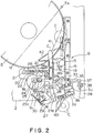
- the inlet portion of the coin passage 6 has a passage inlet bottom plate 15 in substantially the same surface as the rotating plate 5, a fixed passage member 16 and a moving passage member 17, the widths L (see FIG. 1) of which are determined so as to correspond to a coin diameter and which are provided after the passage inlet bottom plate 15, and a passage exit bottom plate 18 provided to a downstream side of the fixed passage member 16 and the moving passage member 17.
- a small-diameter coin exclusion hole 19 provided between the passage inlet bottom plate 15 and the passage exit bottom plate 18.
- the following is a description of the configuration of the coin passage which includes the passage width adjustment portion 141 as the coin passage adjustment means.
- FIG. 2 shows the coin passage when there is the status of maximum width
- FIG. 3 shows the coin passage when there is the status of minimum width
- the moving passage member 17 has an extending portion 20 which extends horizontally in a direction to the rear of a straight edge portion 17b which has a step 17a and which configures the coin passage 6, and this extending portion 20 engages with the guide rollers 22, 22 which turn in the long holes 21, 21 on the side of the machine unit 2 and which are made in a direction which is perpendicular to the edge portion 17b, and are supported so that a moving passage member 17 can move in a straight line so as to advance towards and retreat from the fixed passage member 16.
- This stepless cam 25 has a spiral shape for which the radius increases from the minimum radius portion 25a to the maximum radius portion 25b, and to the minimum radius portion 25a is a moving passage member 17 which is in the status of maximum opening when the cam follower 23 engages with a concave portion 25c formed in the stepless cam 25.
- This status of maximum opening is a set position.
- S1 is a coin passage maximum opening portion detection sensor. The 25 is rotated through a required angle by the coin passage width adjustment pulse motor M1.
- auxiliary passage member 27 which has an L-shape when seen in plan, and which is connected at one end by a pin 28, while the other end of this auxiliary passage member 27 is urged by a spring 30 so that it is contact with a guide 29 which is fixed to the side of the machine unit 2, so that when the position of the contact surface 27a changes with movement of the auxiliary passage member 27 and the edge portion 17b of the moving passage member 17 is at a slightly curved position with respect to the edge portion 17b as shown in FIG. 2 for when the passage width increases, and deforms to a linear shape with respect to the edge portion 17b of the moving passage member 17 when the passage width decreases.
- the distal end portion of the side passage exit bottom plate 18 which is on the side of the moving passage member 17, is supported by the pivot 31 so as to be freely rotatable in the side of the machine unit 2, and a pin 32 provided to the bottom surface of this passage exit bottom plate 18 engages with a long hole 34 of the portion 33 which extends to the side of the moving passage member 17 which is on the side of the coin passage 6, and movement of the moving passage member 17 so that the passage width narrows, causes the passage exit bottom plate 18 to rotate via the pin 32, in the clockwise direction in the figure and about the pivot 31.
- a auxiliary passage member 35 which is on a line extending upwards from the edge portion 16b of the fixed passage member 16 and which has the step 16a, a sensor S2 to count the number of passes of coins to the downstream side, and a sensor S3 to check whether or not a coin has passed, and between these sensors S2 and S3 is provided a stopper which acts by a solenoid (not shown) two stop passage of following coins once a required number of coins has passed. This stopper is provided so that it enters into the path of passing coins.
- auxiliary passage member 35 coin passage passed coin total number count sensor S2 and coin passage passage detection sensor S3 are arranged in a status so that a virtual line linking them is close to a horizontal line with respect to the contact surface 27a of the auxiliary passage member 27 on the side of the moving passage member 17.
- S4 is a sensor which detects the presence and the level of a coin on the rotating plate 5, while 41 is a thickness regulating member which prevents two overlapping coins from entering the coin passage 6, by creating a gap which is larger than the thickness of one of the coins being handled but smaller than the thickness of two coins.
- 42 is a guide plate which is placed on the rotating plate 5 and mounted to the moving passage member 17, and which ensures that the coins which are moved on the rotating plate 5 are led to the downstream side of the direction of rotation and do not remain, and C represents a coin.
- FIG. 4 The support mechanism for this conveyor belt 43 is shown in the disassembly perspective view of FIG. 4, while FIG. 5 and FIG. 6 are sectional views for the case when the height of the conveyor belt 43 is at the highest position and the lowest position.
- Each of the ends of the two blocks 46, 46 before and after the forward and rear bearings 45, 45 of the fixed plate 44 which is fixedly provided to the side of the machine unit 2 are pivoted by pivots 47, 47, and at the opposite ends of these blocks 46, 46 are bearing portions 49, 49 on the upper portion of the moving frame 48 and which are pivoted by the pivots 50, 50.
- the bearing portions 51, 51 at the lower end of the blocks 46, 46 are linked by a link 52 which configures a parallel four-jointed link mechanism.
- a pulley 53 on the inlet side of the conveyor belt 43 is mounted by a pivot 54 to the side surface of the moving frame 48, and the pulleys 55, 56 on the downstream side of the same are pivotably mounted to the rocker plate 57, the center portion of this rocker plate 57 being pivoted by a pivot 58 in the side surface of the moving frame 48 and the other end of which is in contact with a stopper 61 mounted to the moving frame 48 so that the drop of the pulleys 55, 56 is regulated.
- a tension spring 60 across the rocker plate 57 and the member 59 which has a pressing roller 43, and this spring acts to press upwards at a constant force irrespective of the position of the height of the moving frame 48. This is to say that it allows the rocker plate 57 to escapee upwards when thick coins have entered.
- a tension spring 62 is stretched across the moving frame 48 and the fixed plate 44 and always urges the moving frame 48 in the upwards direction.
- the base portion of the detection plate 63 is pivoted by a pivot 64 in the downstream end of the moving frame 48 and in the vicinity of the pivot 64 is provided a contact portion 65 which detects the height of stacking of coins at the upper portion of the coin stacking portion 7.
- the detection portion 64 at the distal end relates to a photo-sensor S5 provided to the moving frame 48 and when the detection portion 64 is activated, there is detection that there is no longer an empty upper portion of the coin stacking portion 7.
- a DC motor M2 To the lower surface of the fixed plate 44 is provided a DC motor M2 and on the shaft which is rotated by this motor are respectively fixed a set position detection plate 66, a stepless cam 67 and a rotation angle detection slit plate 68, and to the periphery of this set position detection plate 66 is provided the coin passage set position detection sensor S6 while to the periphery of the rotation angle detection slit plate 68 is provided a rotation angle detection sensor S7.
- a cam follower 69 pivoted at the center position of the moving frame 48 is in contact with the stepless cam 67, and the rotation of this stepless cam 67 moves the moving frame 48 up and down via the cam follower 69, so that the position of contact of the cam follower 69 is a set position at the position of minimum radius of the stepless cam 67.
- the thickness regulating member 41 is fixed to the end of the inlet of the moving frame 48 and the height of the thickness regulating member 41 is also adjusted to the thickness of the coins handled, in accordance with the rise and fall of the moving frame 48.
- 70 indicates a pulley which receives the rotational force from the drive motor of the conveyor belt 43.
- the left and right belts 77, 78 are wound around the pulleys 73, 74 and 75, 76 which are pivoted and which form pairs in the upper and lower portions of the left and right blocks 71, 72.
- the coins are in a stacked status between opposing surfaces of these belts 77, 78 and so the coin support portions 79, 79, 80, 80 which protrude into the outer surface of the belts 77, 78 are provided to symmetrical positions of the left and right belts 77, 78.
- two coin support portions are provided so that they overlap twice for one revolution of the belts 77, 78.
- the left and right blocks 71, 72 are urged towards each other by a tension spring 81.
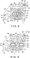
- a parallel link mechanism enables stepless adjustment of the blocks 71, 72 so that they come towards and away from each other.
- This link mechanism comprises a first link 83 which has its central portion supported so as to be freely rotatable in a horizontal plane by a pivot 83a in a base 82, and is linked by a block 71 pivoted by a pivot 71a at a distal end, a second link 86 which has its central portion supported so as to be freely rotatable in a horizontal plane by a pivot 84 in a base 82 and a distal end having a block 72 of another side being linked by a pivot 85, a third link 88 in which one end is linked to said block 71 by said pivot 71a and the other end of which is linked to another end of said second link 2 by a pin 87, and fourth and fifth links 89,90 which have one end linked to the side of the surface opposite the blocks 71, 72 and the other ends pivoted in the side of the base 82.
- a central portion of a lever 94 which has at its distal end a closing member 93 which closes the open surface of the side of coin entry between the belts 77, 78 is pivoted by the pivot 84 in the base 82, and a pin 97 at the other end of the lever 94 engages with and is freely linked with a long hole 96 at the other end of the link 95 which is linked to the other end portion of the first link 83, and this lever 94 is always urged by a tension spring 98 in the direction of separation from the coin stacking portion 7.
- Guide levers 99,100 are fixed to the blocks 71, 72 so as to prevent the escape of coins when the coins are stacked.
- the drive means for the belts 77, 78 of the coin stacking portion 7 is configured from gears 103, 104 fixed to the shafts 101, 102 of the pulleys 74, 76 of the lower portion of the belts 77, 78, the arms 105, 106 which engaged with the shafts 101, 102 and supported by them so as to be freely rotatable, and a member 112 which can be freely raised and lowered along a vertical guide rod 111 which is supported by the shafts 109, 110 of the gears 107, 108, and the drive gear 113 which rotates by the pulse motor M4 engages with the gear 103 on the shaft of the other pulley 74, and each of the gears 103, 107, 108, 104 are always engaged. Accordingly, even if there is change in the interval between the belts 77, 78, the rotation of the drive gear gear 103, 107, 108, 104 are always engaged. Accordingly, even if there is change in the interval between the belts 77
- packaging portion 10 of the conventional configuration is able to correspond to any type of coin and so the conventional configuration, details of which are therefore omitted here, is used.
- this panel portion 114 has a key portion 115 having a ten-key pad to one side, and which also includes a specification button for the number of batches when there is the totaling mode, and for the number of batches when there is the packaging mode, and a mode switching button 117 for packaging and totaling.
- the operation of the key portion 115 enables the input of the type, diameter, thickness and the packaging unit number for the coins to be processed.
- the other side of the panel portion 114 display portion 118 and includes a position display portion 119 which indicates the place at which some abnormality has occurred, a contents display portion 120 which indicates the type of abnormality, a mode display 121 for the total number, batch and the like, a display 122 for the number of coins/rolls, a stored coin type display 123 for written entry in which is written the type of coins for which coin information is stored, a coin type display 124 which shows the currently specified coins, and a packaged roll number display 125 which shows the current number of coins which is the packaging unit.
- a coin/roll number switching button 126 Separately from this are a coin/roll number switching button 126, a clear button 127, a start button 128, a stop button 129, and a down button 130 and an up button which specify the coin type for processing, and which successively display the display contents displayed in the coin type display and the packaging coin number display 125 in the order of storage, that is, in the order in which they were recorded in the stored coin type display 123.
- the coin information input unit 135 includes the key portion 115 and includes a method for the prior storage of coin information in an information storage media such as a ROM or an IC card or the like, and for the input of coin information to it.
- the display unit 136 comprises a position display unit 119, a contents display unit 120, a mode display 121, a number of rolls/coins display 122 and the stored coin type display 123.
- the storage unit 137 stores coin information which has been input by the coin information input unit 135 and so that there is a correspondence with the coin type and therefore corresponds to the coin information storage means disclosed herein. Moreover, storage unit 137 uses an EEPROM for example, so that the stored contents are not erased even if the power is cut.
- the coin counting unit 138 comprises the coin passage passed coin total number count sensor S2 and the coin passage passage detection sensor S3 and the coin stop unit 139 comprises the stopper 36 and a solenoid (now shown), the coin supply unit 140 comprises the rotating plates 4, 5 and the motors which drive them, and the passage width adjustment unit 141 is configured from the pulse motor M1, the portion detection sensor S1 and the stepless cam 25.
- the passage height adjustment unit 142 comprises a configuration having the DC motor M2, and a rotation position detection sensor comprising the position detection sensor S6 and the rotation angle detection sensor S7, while the coin stacking portion inner diameter adjustment unit 143 is a configuration comprising the pulse motor M3, the set position detection sensor S8 and the stepless cam 92.
- the coin stacking unit 144 comprises a pair of belts 77, 78 and the pulse motor M4 which rotates the belts 77, 78, while the coin packaging unit 145 comprises the three packaging rollers 9, 9, 9 and the motors and the like which rotationally drive them (not shown).
- the coin information input unit 135 is used to set coin information such as the type of coins, their thickness, their diameter and the packaging coin number unit and other information about the currency of the shipment or export destination in a ROM or an IC card, and this coin information is stored in the storage unit 137. If there is a partial change in the coin information or if there is the addition of one type of coin, then this can be performed by operating the key portion 115 at the destination of shipment. All of the coin information can be input by operating the key portion 115.
- FIG. 15 is a block diagram showing storage contents of the storage unit 137. The following is a description of one example of the storage contents of the coin block 1.
- the date of update of that coin block is stored in the first storage region 151 .
- This date of update is given by a clock provided inside the control unit 132 and is automatically set and updated each time input is performed in the normal input mode to be described later.
- the diameter D (1) of a coin is stored in the storage region 152 and the thickness T (1) of a coin is stored in the storage region 153.
- These items of coin information are stored in units of up to 1/00th of a millimeter. Moreover, the units can be selected so that storage can be performed in inches or some other unit.
- the coin passage width information P1 is stored in the storage region 154.
- This P1 indicates the number of input pulses to the pulse motor of the passage width adjustment unit 141 to drive the moving passage member 17 (See FIG. 1) so that the selector groove width L (See FIG. 1) can be made a required value, and is either calculated by the control unit 132 in accordance with the diameter D (1) of the coin or is directly input by a special input mode to be described later, and stored.
- the coin passage height information P2 is stored in the storage region 155.
- This P2 indicates the number of output pulses of the rotation angle detection sensor S7 to rotate the DC motor M2 to make the thickness regulating member 41 (See FIG. 4) the required height. More specifically, the DC motor M2 stops when the number of output pulses of the rotation angle detection sensor S7 since the start of rotational drive of the DC motor M2 has reached the number P2.
- This P2 can either be calculated by the control unit 132 using the thickness T(1) of the coins, or can be directly input by a special input mode to be described later.
- C3, C4 use values which differ according to the design values and the like for the thickness regulating member 41.
- the coin stacking portion inner diameter information P3 is stored in the storage region 156. This P3 indicates the number of input pulses to the pulse motor of the coin stacking portion inner diameter adjustment portion 143 so that the setting for the gap between the belts 77, 78 (See FIG. 7) can be changed in accordance with the diameter D(1) of the coins, and can either be calculated by the control portion 132 or can be directly input by a special input mode to be described later.
- the equation for calculation in accordance with the diameter of the coins is given as the following.
- the coin support portion lowering pattern is stored in the storage region 157.
- This coin support portion lowering pattern is information which determines the drive pattern of the belts 77, 78 and the lowering pattern of the coin support portion 79, 80 which are provided to the belts 77, 78.
- the coin support portions 79, 80 lower as coins are stacked one by one but the amount of lowering is not always constant, but rather changes in accordance with a constant pattern.
- the coin support portion lowering pattern is information which expresses the change pattern for the amount of lowering, and is determined in accordance with the thickness T(1) of the coins but is the same as that which has been described in detail in Japanese Patent Laid-Open Publication No. 17704-1991.
- the storage unit 137 holds the coin support portion lowering pattern as a table which has been determined beforehand in accordance with the thickness T(1) of the coins, and reads this table in accordance with the thickness T(1) of the input coins and stores it in the storage table 157.
- FIG. 14 is a flowchart which indicates the operation procedures for the input and correction of the coin information D(1),T(1),M(1) described above, by operation of the key portion 115.
- the key portion 115 is operated and the coin type setting mode is specified (S1401).
- this mode is specified when the keys "A”, “F”, and “ST” are pressed in succession.
- the numerical values input by the operations are displayed on the display portions 122, 124 and the like.
- the input mode is then selected (S1402).
- the normal mode is specified when the coin information, which in this embodiment are the diameter and the width of the coins, and the number of coins which is the packaging unit, are to be input.
- the special input mode is selected when the coin passage width information P1, the coin passage height information P2 and the coin stacking portion inner diameter information P3 calculated from the coin information by the control portion 132 are to be fine adjusted.
- the successive pressing of the "3" and the "ST” keys specifies the normal input mode
- the successive pressing of the "4" and the "ST” keys specifies the special input mode.
- Selection of the coin block is performed (S1404) when it is judged that the normal input mode has been specified as the input mode (S1403). Selection of the coin block is performed using the down button 130 and the up button 131 while observing the coin types which are shown in the upper surface of the storage coin type display 123, and by shifting the selected coin type block until the required coin type block is reached.
- coin information is stored for the selected coin type block (S1405) that information is displayed in the display portions 122, 124 (S1410).
- "-" is displayed if coin information is stored for the selected coin type block.
- the key portion 115 is operated for the successive input of each type of coin information (S1406).
- the control unit 132 successively calculates the coin passage width information P1, coin passage height information P2 and the coin stacking portion inner diameter information P3 on the basis of the input coin information and stores them in the appropriate coin blocks inside the storage portion 137 (S1407).
- S1408 When all of the input information has been input (S1408), there is the end of input with respect to that coin type block.
- the diameter D(1) of a coin is first input as the coin information. Doing this first involves pressing the keys “1", “3” and “ST” in sequence with the mode for the input of the diameter D(1) being selected and then using the numerical keys to input the diameter in mm units to two decimal places, and finally pressing the "ST” key again.
- the keys "1", “3", “ST", “2”, “6”, "5", "0” and “ST” are pressed in sequence.
- the diameter D(1) is input, the calculations described above are performed and the coin passage width information P1 and the coin stacking portion inner diameter information P3 which are the results of the calculation are stored in the storage portion 137.
- the packaging coin number unit is then input as the third item of coin information.
- This is a numerical value which expresses the number of coins which are to be packaged into a single roll.
- the keys "1", “2” and “ST” are pressed in order, and then the number keys are used to input the numerical value (a positive integer) and finally pressing the "ST” key again.
- the keys "1", “2", “ST”, “2”, “5" and “ST” are pressed in sequence.
- the packaging coin number unit is also input as coin information but it is not necessarily required, as it is set to a predetermined number if its specification has been omitted.
- the special input mode is information which has been calculated on the basis of coin information which has been input by the normal input mode, and uses manual input to change the coin passage width information P1, coin passage height information P2 and the coin stacking portion inner diameter information P3.
- This mode is used for example, when actual packaging operation has been performed on the basis of the calculated information and there is some problem with the results, and when it is required to raise the accuracy. Moreover, it is not possible to input the renewal date, the diameter D(1) of the coin or the thickness T(1) of the coin from the special input mode.
- selection of the coin type block is performed (S1414) in the same manner as for S1404. Then, the display portions 122, 124 display the coin information for the selected coin type block (S1415).
- the display portion 122 displays the stored values for the coin passage width information P1.
- this value is to be corrected, input is performed using the keys of the key portion 115, and the appropriate stored values in the storage portion 137 are rewritten (S1418 ⁇ S1420).
- the keys "2" and “6" of the key portion 115 are pressed in sequence when the coin passage width information P1 is to be changed.
- the selector groove width L, the height of the thickness regulating member 41 and the gap between the belts 77, 78 are at their widest when in their respective initial statuses and so they become smaller for larger values of coin passage width information P1, coin passage height information P2 and coin stacking portion inner diameter information P3.
- This coin type specification is used as the basis for the control unit 132 to read the coin information for that coin type from the storage unit 137, and after the set position return command has been given to each adjustment portion and each adjustment portion returned to a set position, the motors of each adjustment portion are rotated by the calculated number of pulses and rotation amounts so that each adjustment portion is automatically adjusted.
- the number of pulses of the pulse motor M3 and which are necessary to adjust the inner diameter of the coin stacking portion 7 so that it is slightly larger than the diameter, the amount of rotation of the DC motor M2 and which is necessary to adjust the passage height of the coin passage 6 to a height suitable for that thickness, and the number of pulses of the pulse motor M1 and which are necessary to adjust the passage width of the coin passage 6 so that it is slightly larger than the diameter of the coin type, are respectively calculated and stored in the storage portion 137 when there is input of the diameter and the thickness.
- the stepless cam 25 rotates in accordance with the rotation of the pulse motor M1, and rotates clockwise through a required angle from the set position shown in FIG. 2, presses the cam follower 23 and the guide action of the guide rollers 22, 22 and the long holes 21, 21 move the moving passage member 17 in the direction of the right in FIG. 2, and stops it at a required gap with respect to the fixed passage member 16.
- the passage width corresponding to the diameter of the coin of the set coin type.
- the stepless cam 25 has a peripheral surface for which the diameter changes without steps and so it is possible to adjust the width of the passage to one pitch of a rotation angle due to one pulse of the pulse motor M1, and for effectively stepless adjustment to be possible, and for the passage width to be able to correspond to coins of any diameter as long as the diameter is within the range of the maximum passage width and the minimum passage width.
- the pin 28 which is the support point for the auxiliary passage member 27 also moves and in accordance with this, the passage surface 27a forms an increasingly smaller angle with respect to the edge portion 17b of the moving passage member 17, and approaches a straight line.
- the movement of the moving passage member 17 causes the passage exit bottom plate 18 to rotate clockwise and displace about the pivot 31 and via the long hole 34 and the pin 32, and for the auxiliary passage member 35, and the sensors S2 and S3 to be positioned parallel to the passage surface 27a of the auxiliary passage member 27.
- the passage formed by the auxiliary passage member 27 and the auxiliary passage member 35 deforms to a straight line and the end projects to approach the coin stacking portion 7, so that there is no change in the status of insertion to the coin stacking portion 7 irrespective of the coin diameter.
- the passage height adjustment unit 142 has the stepless cam 67 is rotated through a required amount of rotation by the rotation of the DC motor M2 and presses down the cam follower 69 so that the moving frame 48 is lowered to oppose the urging of the spring 62, and so that the height of the position of the lower surface of the conveyor belt 43 is adjusted to a position where the it presses against the upper surface of the coins of the set coin type.
- the thickness regulating member 41 is also adjusted to a position of a height where only a single coin thickness can pass under its lower surface.
- the rotation of the pulse motor M3 rotates the stepless cam 92 from the position shown in FIG. 8 and clockwise through a required angle corresponding to the number of pulses.
- the cam follower 91 is pressed by the cam surface and gradually moves in a direction away from the center of the cam 92, while the first link 83 rotates clockwise around the pivot 82a and the block 71 linked to one end of it is moved to the left of the figure.
- the second link 86 rotates in the anticlockwise direction about the pivot 84 and via the third link 88, and the block 72 on the other side moves to the right.
- the rotation of the first link 83 displaces the lever 94 in the clockwise direction about the pivot 84 and via the link 95, and the closing member 93 at its distal end retreats to take a position suited to the increase in the gap between the belts 77, 78.
- the inner diameter of the coin stacking cavity formed by the belts 77, 78, the closing member 93 and the guides 99, 100 is steplessly adjusted to a size suited to the outer diameter of the coins of the set coin type.
- the arms 105,106 are linked by the pivots 109, 110 to the member 12 and accompanying movement of the belts 77, 78 to the left and right, displace to become straighter and follow the widening of the space between the belts 77, 78 but the gears 107, 108 are in a state of constant meshing and so the drive force of the motor M4 is transmitted to the pulleys 74, 75 of the belts 77, 78 via the gears 113, 103, 107, 108, 04 and irrespective of a change in the gap between the left and right belts 77, 78.
- the passage width and passage height of the coin passage 6 and the inner diameter of the coin stacking portion 7 are all set to values suited to the coin diameter and coin thickness of the coin type to be processed.
- the rotating plate 4 When the coin type is set and the start button 128 is pressed, the rotating plate 4 is driven and the coins inserted from the coin insertion hopper 3 are supplied to onto the rotating plate 5. At this time, the status of the coins on the rotating plate 5 is monitored by the level sensor S4 and the supply status is controlled.
- the rotation of the rotating plate 5 causes the coins on the rotating plate 5 to pass from the periphery to enter beneath the lower surface of the thickness regulating member 41 so that stacked coins are eliminated and a single layer is made, and this single layer then flows into the coin passage 6 where it is pressed by the lower surface of the conveyor belt 43 on the passage inlet bottom plate 15, and the rotation of the conveyor belt 43 conveys the coins in a status where they are between the fixed passage member 16 of the coin passage 6 and the edge portions 16b, 17b of the moving passage member 17. Small-diameter coins which are smaller than the gap between these edge portions drop from the small-diameter coin exclusion hole 19 between the edges and are excluded.
- the support portions 79, 80 of the left and right belts 77, 78 are positioned close to the upper end, the coins are held by these support portions 79, 80 and after there is one coin held, the signals from the sensor S3 are used as the basis for rotating the pulse motor M4 through a required number of pulses corresponding to the thickness of the coins, and rotating the belts 77, 78 so that the support portions 79, 80 are lowered.
- the stacked coins of the required number and which have entered the coin stacking portion 7 are received by a support means not shown in the figure, by the coin support portions 79, 80 moving from the lower end to the outside, and are left to the packaging portion 10 where they are packaged by packaging paper 8, and the packaged coin roll is discharged from the outlet 11.
- the forward and reverse operation of the rotating plate 5 and the conveyor belts feed any abnormal coins which have remained on the rotating plate 5, back to the coin passage 6 where they are removed by the exclusion hole.
- the passage width and the passage height are returned to their set positions and the coin processing ends automatically.
- the expansion of the passage width and the increase in the passage height can be made to the maximum values but some values less than the maximum values can be used.
- the coin information when the coin information is stored in the storage portion 137, an operator arbitrarily selects a coin type block (See FIG. 15) and stores the coin information in that block but a control portion 132 can select an empty coin type block and store the information in that block.
- a coin type block See FIG. 15
- a control portion 132 can select an empty coin type block and store the information in that block.
- the storage unit 137 can also store other information such as the power frequency and the like.
- the storage unit 137 can be a RAM or the like which has battery backup.
- Each of the items of information need not read from the EEPROM when adjustment is made, but all of the information can be read from the EEPROM when the power is turned on or when settings are stored, and stored in a RAM, and each item of information read from the RAM when adjustment is made.
- the coin passage width information P1, the coin passage height information P2 and the coin collecting portion inner diameter information P3 are calculated when the coin information is input, and are then stored in the storage unit 137 but the information P1, P2 and P3 can be calculated when adjustment is made.
- the coin information which is stored in the storage unit 137 can be stored onto an IC card as backup information.
Landscapes
- Physics & Mathematics (AREA)
- General Physics & Mathematics (AREA)
- Basic Packing Technique (AREA)
- Testing Of Coins (AREA)
Applications Claiming Priority (6)
| Application Number | Priority Date | Filing Date | Title |
|---|---|---|---|
| JP32594391 | 1991-12-10 | ||
| JP325943/91 | 1991-12-10 | ||
| JP3325943A JPH05162727A (ja) | 1991-12-10 | 1991-12-10 | 硬貨包装機 |
| JP35389/92 | 1992-02-21 | ||
| JP03538992A JP3414764B2 (ja) | 1992-02-21 | 1992-02-21 | 硬貨包装機 |
| JP3538992 | 1992-02-21 |
Publications (3)
| Publication Number | Publication Date |
|---|---|
| EP0546772A1 true EP0546772A1 (de) | 1993-06-16 |
| EP0546772B1 EP0546772B1 (de) | 1996-04-24 |
| EP0546772B2 EP0546772B2 (de) | 2005-02-09 |
Family
ID=26374373
Family Applications (1)
| Application Number | Title | Priority Date | Filing Date |
|---|---|---|---|
| EP92311081A Expired - Lifetime EP0546772B2 (de) | 1991-12-10 | 1992-12-04 | Münzverpackungsvorrichtung |
Country Status (7)
| Country | Link |
|---|---|
| US (1) | US5435777A (de) |
| EP (1) | EP0546772B2 (de) |
| KR (1) | KR970004742B1 (de) |
| CA (1) | CA2084459C (de) |
| DE (1) | DE69210188T3 (de) |
| ES (1) | ES2089422T3 (de) |
| TW (1) | TW229188B (de) |
Cited By (3)
| Publication number | Priority date | Publication date | Assignee | Title |
|---|---|---|---|---|
| EP0615216A2 (de) * | 1993-03-08 | 1994-09-14 | Glory Kogyo Kabushiki Kaisha | Münzverpackungsmaschine und Verwaltungssystem dafür |
| EP0620539A1 (de) * | 1993-04-15 | 1994-10-19 | Laurel Bank Machines Co., Ltd. | Münzenbehandlungsmaschine |
| EP0631261A1 (de) * | 1993-06-28 | 1994-12-28 | Standardwerk Eugen Reis Gmbh | Vorrichtung zum Stapeln von Münzen oder ähnlichen scheibenförmigen Gegenständen |
Families Citing this family (22)
| Publication number | Priority date | Publication date | Assignee | Title |
|---|---|---|---|---|
| US7028827B1 (en) | 1992-09-04 | 2006-04-18 | Coinstar, Inc. | Coin counter/sorter and coupon/voucher dispensing machine and method |
| US6736251B2 (en) | 1992-09-04 | 2004-05-18 | Coinstar, Inc. | Coin counter and voucher dispensing machine and method |
| US6494776B1 (en) * | 1992-09-04 | 2002-12-17 | Coinstar, Inc. | Coin counter/sorter and coupon/voucher dispensing machine and method |
| US5573457A (en) * | 1995-03-07 | 1996-11-12 | Cummins-Allison Corp. | Coin Wrapping system with touch screen device |
| US5940623A (en) | 1997-08-01 | 1999-08-17 | Cummins-Allison Corp. | Software loading system for a coin wrapper |
| SE9904220D0 (sv) * | 1999-11-22 | 1999-11-22 | Scan Coin Ind Ab | A device for packaging coins in plastic bags |
| US6499277B1 (en) | 2000-02-22 | 2002-12-31 | Cummins-Allison Corp. | Coin wrapper |
| EP2541509A1 (de) | 2002-02-15 | 2013-01-02 | Coinstar, Inc. | Verfahren und Systeme zum Austauschen und/oder Übertragen unterschiedlicher Formen von Werten |
| US8033375B2 (en) | 2002-02-15 | 2011-10-11 | Coinstar, Inc. | Methods and systems for exchanging and/or transferring various forms of value |
| US7865432B2 (en) | 2002-02-15 | 2011-01-04 | Coinstar, Inc. | Methods and systems for exchanging and/or transferring various forms of value |
| AU2003239234A1 (en) * | 2002-06-14 | 2003-12-31 | Cummins-Allison Corp. | Coin redemption machine having gravity feed coin input tray and foreign object detection system |
| US7438172B2 (en) * | 2002-06-14 | 2008-10-21 | Cummins-Allison Corp. | Foreign object removal system for a coin processing device |
| JP2008217581A (ja) * | 2007-03-06 | 2008-09-18 | Hymex Kk | 円板状体の繰出し装置 |
| CA2815428C (en) | 2010-11-01 | 2019-09-24 | Coinstar, Inc. | Gift card exchange kiosks and associated methods of use |
| US8874467B2 (en) | 2011-11-23 | 2014-10-28 | Outerwall Inc | Mobile commerce platforms and associated systems and methods for converting consumer coins, cash, and/or other forms of value for use with same |
| US9129294B2 (en) | 2012-02-06 | 2015-09-08 | Outerwall Inc. | Coin counting machines having coupon capabilities, loyalty program capabilities, advertising capabilities, and the like |
| US9036890B2 (en) | 2012-06-05 | 2015-05-19 | Outerwall Inc. | Optical coin discrimination systems and methods for use with consumer-operated kiosks and the like |
| US8967361B2 (en) | 2013-02-27 | 2015-03-03 | Outerwall Inc. | Coin counting and sorting machines |
| US9022841B2 (en) | 2013-05-08 | 2015-05-05 | Outerwall Inc. | Coin counting and/or sorting machines and associated systems and methods |
| US9443367B2 (en) | 2014-01-17 | 2016-09-13 | Outerwall Inc. | Digital image coin discrimination for use with consumer-operated kiosks and the like |
| US9235945B2 (en) | 2014-02-10 | 2016-01-12 | Outerwall Inc. | Coin input apparatuses and associated methods and systems |
| US10346819B2 (en) | 2015-11-19 | 2019-07-09 | Coinstar Asset Holdings, Llc | Mobile device applications, other applications and associated kiosk-based systems and methods for facilitating coin saving |
Citations (4)
| Publication number | Priority date | Publication date | Assignee | Title |
|---|---|---|---|---|
| US4060093A (en) * | 1972-03-01 | 1977-11-29 | Glory Kogyo Kabushiki Kaisha | Coin stacker in automatic coin wrapping apparatus |
| US4098056A (en) * | 1975-08-22 | 1978-07-04 | Glory Kogyo Kabushiki Kaisha | Coin passage device of a coin processing machine |
| US4333296A (en) * | 1979-03-15 | 1982-06-08 | Tokyo | Coin wrapping machine |
| WO1991008952A1 (en) * | 1989-12-18 | 1991-06-27 | Cummins-Allison Corp. | Automatic adjustment device for a coin wrapping mechanism |
Family Cites Families (6)
| Publication number | Priority date | Publication date | Assignee | Title |
|---|---|---|---|---|
| JPS5246993A (en) * | 1975-10-09 | 1977-04-14 | Glory Ltd | Coin packing machine |
| US4126146A (en) * | 1975-10-17 | 1978-11-21 | Glory Kogyo Kabushiki Kaisha | Coin delivering device of coin processing machine |
| SU1408445A1 (ru) * | 1986-12-05 | 1988-07-07 | Ленинградское Опытно-Конструкторское Бюро Табачного И Торгового Машиностроения | Устройство дл накоплени и выдачи монет различного достоинства |
| JPH085452B2 (ja) * | 1986-12-26 | 1996-01-24 | グローリー工業株式会社 | 硬貨包装機 |
| JPH0682410B2 (ja) * | 1988-08-31 | 1994-10-19 | ローレルバンクマシン株式会社 | 硬貨包装機 |
| JPH02193286A (ja) * | 1988-10-19 | 1990-07-30 | Laurel Bank Mach Co Ltd | 硬貨処理機の硬貨除去装置 |
-
1992
- 1992-12-03 TW TW081109709A patent/TW229188B/zh active
- 1992-12-03 CA CA002084459A patent/CA2084459C/en not_active Expired - Fee Related
- 1992-12-04 DE DE69210188T patent/DE69210188T3/de not_active Expired - Lifetime
- 1992-12-04 EP EP92311081A patent/EP0546772B2/de not_active Expired - Lifetime
- 1992-12-04 ES ES92311081T patent/ES2089422T3/es not_active Expired - Lifetime
- 1992-12-09 US US07/987,592 patent/US5435777A/en not_active Expired - Lifetime
- 1992-12-10 KR KR1019920023971A patent/KR970004742B1/ko not_active IP Right Cessation
Patent Citations (4)
| Publication number | Priority date | Publication date | Assignee | Title |
|---|---|---|---|---|
| US4060093A (en) * | 1972-03-01 | 1977-11-29 | Glory Kogyo Kabushiki Kaisha | Coin stacker in automatic coin wrapping apparatus |
| US4098056A (en) * | 1975-08-22 | 1978-07-04 | Glory Kogyo Kabushiki Kaisha | Coin passage device of a coin processing machine |
| US4333296A (en) * | 1979-03-15 | 1982-06-08 | Tokyo | Coin wrapping machine |
| WO1991008952A1 (en) * | 1989-12-18 | 1991-06-27 | Cummins-Allison Corp. | Automatic adjustment device for a coin wrapping mechanism |
Non-Patent Citations (1)
| Title |
|---|
| DATABASE WPIL Week 8903, Derwent Publications Ltd., London, GB; AN 89-022250 & SU-A-1 408 445 (LENGD TABACCO TRADE) * |
Cited By (5)
| Publication number | Priority date | Publication date | Assignee | Title |
|---|---|---|---|---|
| EP0615216A2 (de) * | 1993-03-08 | 1994-09-14 | Glory Kogyo Kabushiki Kaisha | Münzverpackungsmaschine und Verwaltungssystem dafür |
| EP0615216A3 (de) * | 1993-03-08 | 1994-11-23 | Glory Kogyo Kk | Münzverpackungsmaschine und Verwaltungssystem dafür. |
| EP0620539A1 (de) * | 1993-04-15 | 1994-10-19 | Laurel Bank Machines Co., Ltd. | Münzenbehandlungsmaschine |
| US5557908A (en) * | 1993-04-15 | 1996-09-24 | Laural Bank Machine Co., Ltd. | Coin processing machine |
| EP0631261A1 (de) * | 1993-06-28 | 1994-12-28 | Standardwerk Eugen Reis Gmbh | Vorrichtung zum Stapeln von Münzen oder ähnlichen scheibenförmigen Gegenständen |
Also Published As
| Publication number | Publication date |
|---|---|
| CA2084459A1 (en) | 1993-06-11 |
| EP0546772B1 (de) | 1996-04-24 |
| TW229188B (de) | 1994-09-01 |
| US5435777A (en) | 1995-07-25 |
| ES2089422T3 (es) | 1996-10-01 |
| DE69210188T3 (de) | 2005-07-21 |
| DE69210188D1 (de) | 1996-05-30 |
| KR970004742B1 (ko) | 1997-04-03 |
| EP0546772B2 (de) | 2005-02-09 |
| DE69210188T2 (de) | 1997-01-09 |
| CA2084459C (en) | 1998-12-01 |
Similar Documents
| Publication | Publication Date | Title |
|---|---|---|
| EP0546772B1 (de) | Münzverpackungsvorrichtung | |
| US4733765A (en) | Cash handling machine for handling mixtures of notes and coins introduced together | |
| DE3915030C2 (de) | ||
| DE60027945T2 (de) | Banknotenanordnungsvorrichtung | |
| US6499277B1 (en) | Coin wrapper | |
| EP1035520B1 (de) | Banknotenanordnungsvorrichtung | |
| EP1035521A1 (de) | Banknotenanordnungsvorrichtung | |
| US3938303A (en) | Coin packaging apparatus | |
| US5513481A (en) | Coin handling machine | |
| EP0615216B1 (de) | Münzverpackungsmaschine und Verwaltungssystem dafür | |
| US4877232A (en) | Paper discharge apparatus | |
| JP3267697B2 (ja) | 硬貨処理機 | |
| EP0620539B1 (de) | Münzenbehandlungsmaschine | |
| JP3414764B2 (ja) | 硬貨包装機 | |
| JP3267696B2 (ja) | 硬貨処理機 | |
| EP0620540B1 (de) | Münzeneinwickelmaschine | |
| JP2004005746A (ja) | 硬貨類処理機の通路幅調節装置 | |
| EP0620538A1 (de) | Münzeneinwickelmaschine | |
| GB2111951A (en) | Sheet delivery mechanisms | |
| JPH06301835A (ja) | 硬貨処理機 | |
| JPH0555274U (ja) | 硬貨処理機の硬貨通路幅調節装置 | |
| JPH05178335A (ja) | 硬貨処理機 | |
| JPH06301836A (ja) | 硬貨処理機 | |
| JPH0554205U (ja) | 硬貨集積装置 |
Legal Events
| Date | Code | Title | Description |
|---|---|---|---|
| PUAI | Public reference made under article 153(3) epc to a published international application that has entered the european phase |
Free format text: ORIGINAL CODE: 0009012 |
|
| AK | Designated contracting states |
Kind code of ref document: A1 Designated state(s): DE ES FR GB IT SE |
|
| 17P | Request for examination filed |
Effective date: 19930726 |
|
| 17Q | First examination report despatched |
Effective date: 19941221 |
|
| GRAH | Despatch of communication of intention to grant a patent |
Free format text: ORIGINAL CODE: EPIDOS IGRA |
|
| GRAA | (expected) grant |
Free format text: ORIGINAL CODE: 0009210 |
|
| AK | Designated contracting states |
Kind code of ref document: B1 Designated state(s): DE ES FR GB IT SE |
|
| REF | Corresponds to: |
Ref document number: 69210188 Country of ref document: DE Date of ref document: 19960530 |
|
| ET | Fr: translation filed | ||
| ITF | It: translation for a ep patent filed |
Owner name: MODIANO & ASSOCIATI S.R.L. |
|
| REG | Reference to a national code |
Ref country code: ES Ref legal event code: FG2A Ref document number: 2089422 Country of ref document: ES Kind code of ref document: T3 |
|
| REG | Reference to a national code |
Ref country code: ES Ref legal event code: FG2A Ref document number: 2089422 Country of ref document: ES Kind code of ref document: T3 |
|
| PLBI | Opposition filed |
Free format text: ORIGINAL CODE: 0009260 |
|
| PLBQ | Unpublished change to opponent data |
Free format text: ORIGINAL CODE: EPIDOS OPPO |
|
| PLBF | Reply of patent proprietor to notice(s) of opposition |
Free format text: ORIGINAL CODE: EPIDOS OBSO |
|
| 26 | Opposition filed |
Opponent name: STANDARDWERK EUGEN REIS GMBH Effective date: 19970110 |
|
| PLBF | Reply of patent proprietor to notice(s) of opposition |
Free format text: ORIGINAL CODE: EPIDOS OBSO |
|
| PLBF | Reply of patent proprietor to notice(s) of opposition |
Free format text: ORIGINAL CODE: EPIDOS OBSO |
|
| PLBQ | Unpublished change to opponent data |
Free format text: ORIGINAL CODE: EPIDOS OPPO |
|
| PLAB | Opposition data, opponent's data or that of the opponent's representative modified |
Free format text: ORIGINAL CODE: 0009299OPPO |
|
| R26 | Opposition filed (corrected) |
Opponent name: STANDARDWERK EUGEN REIS GMBH Effective date: 19970110 |
|
| PLAW | Interlocutory decision in opposition |
Free format text: ORIGINAL CODE: EPIDOS IDOP |
|
| APAC | Appeal dossier modified |
Free format text: ORIGINAL CODE: EPIDOS NOAPO |
|
| APAE | Appeal reference modified |
Free format text: ORIGINAL CODE: EPIDOS REFNO |
|
| PGFP | Annual fee paid to national office [announced via postgrant information from national office to epo] |
Ref country code: ES Payment date: 20011114 Year of fee payment: 10 |
|
| PGFP | Annual fee paid to national office [announced via postgrant information from national office to epo] |
Ref country code: GB Payment date: 20011121 Year of fee payment: 10 |
|
| REG | Reference to a national code |
Ref country code: GB Ref legal event code: IF02 |
|
| PG25 | Lapsed in a contracting state [announced via postgrant information from national office to epo] |
Ref country code: GB Free format text: LAPSE BECAUSE OF NON-PAYMENT OF DUE FEES Effective date: 20021204 |
|
| PG25 | Lapsed in a contracting state [announced via postgrant information from national office to epo] |
Ref country code: ES Free format text: LAPSE BECAUSE OF NON-PAYMENT OF DUE FEES Effective date: 20021205 |
|
| GBPC | Gb: european patent ceased through non-payment of renewal fee | ||
| APBC | Information on closure of appeal procedure deleted |
Free format text: ORIGINAL CODE: EPIDOSDNOA9O |
|
| APBQ | Date of receipt of statement of grounds of appeal recorded |
Free format text: ORIGINAL CODE: EPIDOSNNOA3O |
|
| APBY | Invitation to file observations in appeal sent |
Free format text: ORIGINAL CODE: EPIDOSNOBA2O |
|
| REG | Reference to a national code |
Ref country code: ES Ref legal event code: FD2A Effective date: 20021205 |
|
| APBU | Appeal procedure closed |
Free format text: ORIGINAL CODE: EPIDOSNNOA9O |
|
| PUAH | Patent maintained in amended form |
Free format text: ORIGINAL CODE: 0009272 |
|
| STAA | Information on the status of an ep patent application or granted ep patent |
Free format text: STATUS: PATENT MAINTAINED AS AMENDED |
|
| 27A | Patent maintained in amended form |
Effective date: 20050209 |
|
| AK | Designated contracting states |
Kind code of ref document: B2 Designated state(s): DE ES FR GB IT SE |
|
| REG | Reference to a national code |
Ref country code: SE Ref legal event code: RPEO |
|
| REG | Reference to a national code |
Ref country code: ES Ref legal event code: FD2A Effective date: 20021205 |
|
| APAH | Appeal reference modified |
Free format text: ORIGINAL CODE: EPIDOSCREFNO |
|
| ET3 | Fr: translation filed ** decision concerning opposition | ||
| PGFP | Annual fee paid to national office [announced via postgrant information from national office to epo] |
Ref country code: IT Payment date: 20101229 Year of fee payment: 19 Ref country code: DE Payment date: 20101220 Year of fee payment: 19 |
|
| PGFP | Annual fee paid to national office [announced via postgrant information from national office to epo] |
Ref country code: SE Payment date: 20111213 Year of fee payment: 20 Ref country code: FR Payment date: 20111219 Year of fee payment: 20 |
|
| REG | Reference to a national code |
Ref country code: DE Ref legal event code: R071 Ref document number: 69210188 Country of ref document: DE |
|
| REG | Reference to a national code |
Ref country code: DE Ref legal event code: R071 Ref document number: 69210188 Country of ref document: DE |
|
| REG | Reference to a national code |
Ref country code: SE Ref legal event code: EUG |