EP0545794A1 - Machine électrodynamique à circuit électrique de service intégré - Google Patents
Machine électrodynamique à circuit électrique de service intégré Download PDFInfo
- Publication number
- EP0545794A1 EP0545794A1 EP92403213A EP92403213A EP0545794A1 EP 0545794 A1 EP0545794 A1 EP 0545794A1 EP 92403213 A EP92403213 A EP 92403213A EP 92403213 A EP92403213 A EP 92403213A EP 0545794 A1 EP0545794 A1 EP 0545794A1
- Authority
- EP
- European Patent Office
- Prior art keywords
- printed circuit
- machine according
- intermediate piece
- machine
- intended
- Prior art date
- Legal status (The legal status is an assumption and is not a legal conclusion. Google has not performed a legal analysis and makes no representation as to the accuracy of the status listed.)
- Withdrawn
Links
- 230000005520 electrodynamics Effects 0.000 claims abstract description 14
- 230000002093 peripheral effect Effects 0.000 claims abstract description 4
- 239000000758 substrate Substances 0.000 claims description 27
- OKTJSMMVPCPJKN-UHFFFAOYSA-N Carbon Chemical compound [C] OKTJSMMVPCPJKN-UHFFFAOYSA-N 0.000 claims description 15
- 229910052799 carbon Inorganic materials 0.000 claims description 15
- 210000005069 ears Anatomy 0.000 claims description 8
- 239000003638 chemical reducing agent Substances 0.000 claims description 7
- 238000004804 winding Methods 0.000 claims description 7
- 210000002105 tongue Anatomy 0.000 claims description 4
- 238000009434 installation Methods 0.000 claims description 3
- 230000010287 polarization Effects 0.000 claims description 3
- 238000004080 punching Methods 0.000 claims description 3
- 239000003245 coal Substances 0.000 claims description 2
- 210000000056 organ Anatomy 0.000 claims description 2
- 230000005355 Hall effect Effects 0.000 description 20
- 230000005405 multipole Effects 0.000 description 5
- 238000001514 detection method Methods 0.000 description 4
- 238000010586 diagram Methods 0.000 description 4
- 230000004907 flux Effects 0.000 description 2
- 238000000034 method Methods 0.000 description 2
- 230000003287 optical effect Effects 0.000 description 2
- 230000006698 induction Effects 0.000 description 1
- 238000003780 insertion Methods 0.000 description 1
- 230000037431 insertion Effects 0.000 description 1
- 238000004519 manufacturing process Methods 0.000 description 1
- 239000004065 semiconductor Substances 0.000 description 1
- 238000005476 soldering Methods 0.000 description 1
- 125000006850 spacer group Chemical group 0.000 description 1
Images


Classifications
-
- H—ELECTRICITY
- H02—GENERATION; CONVERSION OR DISTRIBUTION OF ELECTRIC POWER
- H02K—DYNAMO-ELECTRIC MACHINES
- H02K23/00—DC commutator motors or generators having mechanical commutator; Universal AC/DC commutator motors
- H02K23/66—Structural association with auxiliary electric devices influencing the characteristic of, or controlling, the machine, e.g. with impedances or switches
-
- H—ELECTRICITY
- H02—GENERATION; CONVERSION OR DISTRIBUTION OF ELECTRIC POWER
- H02K—DYNAMO-ELECTRIC MACHINES
- H02K5/00—Casings; Enclosures; Supports
- H02K5/04—Casings or enclosures characterised by the shape, form or construction thereof
- H02K5/14—Means for supporting or protecting brushes or brush holders
- H02K5/143—Means for supporting or protecting brushes or brush holders for cooperation with commutators
- H02K5/148—Slidably supported brushes
Definitions
- the present invention relates to an electrodynamic machine whose inductor windings are connected to an electrical power source or to an electrical load by an electrical connection cable.
- the machine is provided with a collector mounted on a rotor which carries windings which must be excited (in the case of an engine), or at the terminals of which an induced electromotive force is collected (in the case of a generator).
- the electrical connection cable is connected to coals mounted in carbon holders and in contact with the conductive blades of the collector. The relative positioning of these parts must be precise and this involves a manufacturing cost.
- the coals which are wearing parts, can be changed. But in the prior art, it is necessary to redo a precise positioning again during reassembly. This operation is often too difficult to envisage.
- the present invention relates to an electrodynamic machine whose windings are connected to a source of electrical energy or to a load by means of an electrical connection cable, connected to conductive areas of a support printed circuit.
- an electrical service circuit fixed relative to a machine casing.
- the invention is characterized in that the carcass is fixed by an intermediate piece, in that the electrical service circuit is mounted inside the intermediate piece in a hollow formed by a peripheral flange facing the interior of the machine when the intermediate piece is mounted on the carcass.
- the invention relates to a machine which comprises an intermediate part which carries legs or shims for fixing the printed circuit on which the electrical service circuit intended to manage the electrical supply of the machine is produced.
- the printed circuit of the machine comprises an insulating substrate of circular shape pierced with a central hole intended to allow the shaft and the collector of the rotor to pass, in that the external periphery of the substrate comprises guide notches for the carbon holder plate on an intermediate piece between the carcass and a reduction gear base, these notches being produced in particular by circular punching with non-symmetrical angles so as to make a polarization during the mounting of the printed circuit in the engine.
- the machine comprises carbon holders provided with tongues or pins intended to penetrate into the corresponding holes of areas of the substrate.
- the machine is such that the intermediate piece includes in particular two ears provided with holes for connection to the base of the reducer and the ears of the carcass.
- the machine is such that the intermediate part comprises centering pins, the upper part of which comprises two pins intended to penetrate into the notches of the substrate, so as to allow the installation of the substrate in an angular position and to cause it to come into abutment on the surface of each pin.
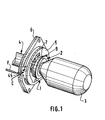
- FIG. 1 there is shown a perspective diagram of a rotor mounted in a printed circuit according to an embodiment of the invention.
- the rotor comprises an armature winding 3 and a collector 7 mounted on a rotation shaft 4.
- the collector 7 passes through a hole drilled on a printed circuit 5 which supports the electrical service circuit which will be described later.
- the printed circuit 5 is mounted on support legs (not shown) mounted on the inner face of a base 6 or intermediate piece which serves to close the carcass (141 in FIG. 10) of the machine, and to carry out its fixing. to a support or other organ such as a gear reducer.
- a wheel 2 is mounted on which is carried an indication 9 of angular position.
- This indication can be obtained, in particular by registering an optically readable mark or by recording magnetic information.
- this indication is constituted by a single indication or mark 9.
- On the printed circuit 5 is mounted a reading member 1 of the indication 9 written or recorded on the wheel 2.
- the nature of the member reading I depends on the nature of the indication (magnetic, optical, or other). This characteristic of the invention resides in that the reading member 1 is carried by the printed circuit 5.
- the intermediate part 6 comprises at least one clearance or light C through which there is access to at least one carbon holder 45, in particular for the purpose of replacing coal without having to modify the relative positioning of the carbon holder 45 and of the collector 7.
- the printed circuit 5 includes terminal blocks not referenced which are described below and which are connected by soldering, in particular to the ends of the wire of a cable F of electrical connection.
- Wheel 2; 11 is constituted by a cylindrical ring 11 mounted on a spacer 15 and fixed in rotation by at least one tongue 17.
- the cylindrical ring carries a succession of magnetic poles N and S which are inscribed therein or inserted by known means.
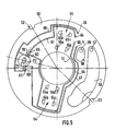
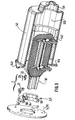
- FIG 3 there is shown a view of the intermediate piece 6 equipped before the insertion of the rotor.
- the printed circuit 5 carries in the lower part of the drawing a reading member I constituted by two Hall effect sensors 20, 22, distributed for example at an angular interval of 10 ° from one another.
- the two sensors 20 and 22 are inserted into housings of a support 21 for the sensors which allows their mechanical fixing and their orientation relative to the rotating member which bears the aforementioned magnetic mark.
- Hall effect sensors consist of a semiconductor package, one face of which must be arranged parallel to the variation in flux to be detected (Hall effect sensor face). Each sensor has three electrical access tabs, positive bias and negative bias (ground) and detection, respectively.
- each sensor 20, 22 is connected to a track 23 on the printed circuit 5.
- This track 23 opens onto a conductive area 27a of the printed circuit 5, onto which a cross member (not shown) is welded.
- the crosspiece is constituted by an elongated conducting body like a paw. It constitutes an element on which one comes to weld during the assembly of the engine, a corresponding wire of an electric cable of connection of the machine.
- each sensor is connected to a track 26 on the printed circuit 5.
- This track 26 opens onto a conductive area 27b of the printed circuit 5, on which a cross member (not shown) is welded.
- the cross member is constituted by a conductive body elongated like a lug. It constitutes an element on which one comes to weld during the assembly of the engine, a corresponding wire of an electric cable of connection of the machine.
- the assembly consisting of zones 27a, 27b, 27c and 27d and of the crosspieces constitutes a part of a terminal block 27, which constitutes in one embodiment the first part (for example, the male part) of a connector, the second of which part is carried by the end of the machine's electrical connection cable.
- the printed circuit carries components (not shown in the drawing) which make it possible to process, on the electrical service circuit 5 itself, the output signals of the sensors 20, 21, 22.
- the service circuit 5 locally executes the interface Electronic control (processing) and machine.
- the electrical supply of the machine is done by means of coals and the connecting cable which also includes wires for connection to the windings of the machine, not shown, and which reach respectively the conductive zones 30 and 31 from which the wires are welded. end wires (not shown) of the stator windings (if the stator is wound) and / or the connecting wires to the coals on the machine collector (machine supply).
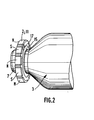
- the intermediate piece 6 has ears on which are drilled holes 37 and 38 for fixing to a flat part of the carcass (not shown) of the machine.
- the electrical service circuit 5 is mounted inside the intermediate piece 6 in a recess formed by a peripheral rim 33. This recess is turned towards the interior of the machine when the intermediate piece is mounted on the carcass.
- the intermediate part 6 carries fixing legs or shims 34 and 36 of the printed circuit on which the electrical service circuit 5 is produced (see new plan).
- fixing lugs 40 to 43 of the carbon holder cases 44 and 45 are inserted into the holes of the printed circuit 5 and are visible on one side in FIG. 3 and visible, on the side of the cases 44 and 45 to Figure 4 (see Figure 6 below).
- the collector 7 passes through a hole in the printed circuit 5 and a hole in the bottom of the intermediate piece.
- the intermediate part 6 is shown installed on the carcass, the latter not being shown.
- FIG 5 there is shown an embodiment of the bare printed circuit intended to equip the intermediate piece 6 of Figure 2.
- the printed circuit comprises an insulating substrate 50 of circular shape pierced a central hole 51 intended to allow the shaft and the rotor collector to pass.
- the outer periphery of the substrate 50 has two notches 52 and 53 for guiding the carbon holder plate on the intermediate piece. These notches are produced by circular punching with non-symmetrical angles so as to make a polarization during the mounting of the printed circuit in the motor.
- the support 50 has been pierced with two zones 54 and 55 in which fixing holes of trapezoidal shape 54a to 54d and 55a to 55d have been produced, intended to receive fixing lugs from each of the two holders. coals on the face not shown in the drawings.
- the substrate 50 carries a first conductive zone 56 intended for supplying the motor. This conductive area 56 is pierced with a hole 57 intended for the passage of a connection crosspiece. On the other hand, the substrate also carries a second conductive zone 58 intended to receive a connection of electrical power ground. This conductive area 58 is pierced with a hole 59 intended for the passage of a connection crosspiece.
- the conductive areas 56 and 58 correspond to the areas 30 and 31 of FIG. 4 and constitute means of connection to the power supply of the machine.
- the substrate 50 then carries tracks 60 and 61 respectively assigned to the common ground of the Hall effect sensors and to the information output of a first Hall effect sensor.
- the track 60 connects a connection zone 61 at the end of the link, to two zones 62 and 63 respectively to ground the first and the second Hall effect sensor respectively (not shown).
- the conductive track 61 is connected to a connection 64 and to a connection 65 on which the information output tab of the first Hall effect sensor is welded.
- the substrate 50 also carries conductive tracks 66 and 67 respectively, for supplying Hall effect sensors to a positive potential on the one hand, and to a Hall effect sensor information output on the other hand.
- the track 66 connects respectively a connection 68 to two connections respectively 69 and 70 on which are fixed the positive supply tabs of the two Hall effect sensors.
- the track 67 connects respectively a connection area 71 to a connection 72 intended to receive the corresponding tab of the second Hall effect sensor. All of the connection zones 61, 64, 69, 70 correspond to the terminal block 27 described in FIG. 3.
- the insulating substrate comprises between the two connection zones of the two Hall effect sensors, 65.70.62 on the one hand, and 72.69.63 on the other hand, a fixing hole 73 of oblong shape intended for the passage of '' a clip-on mounting bracket for the support of the two Hall effect sensors.
- FIG. 6 there is shown a mounting plan of Hall effect sensors on the printed circuit.
- the two Hall effect sensors 20 and 22 are respectively constituted by parallelepipedic housings, the lower face of which is crossed by three connection tabs. These tabs are intended to penetrate into the holes 65, 70, 62 on the one hand, and 72, 69 and 63 already described in FIG. 6.
- the two sensors 20, 22 are introduced by sliding into two housings respectively 82 and 83 of a support 21.
- the support 21 has a central part 85 which is intended to fix the distance between the two sensors 20, 22 on the one hand and which has a curvature making it possible to orient the detection face respectively 86 and 87 of the sensors 20 and 22 on the other hand.
- the support 21 has at its lower part a column 88 of a height H1 determined in function of the final installation position of the wheel 2; 11 and of the reading member 1; 20-22.
- the column 88 has a lower free end of height H2 corresponding to the thickness of the printed circuit 5 and carries two flexible lugs 89 and 90 having shoulders 91 and 92.
- the foot 89-92 is intended to penetrate into the hole 73 of the substrate 50 already described in FIG. 6. During the introduction, the two pins 89.90 hang on and are released when the shoulders 91.92 come out through the free face of the substrate 50.
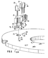
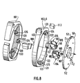
- FIG 7 there is shown a more complete assembly diagram.
- a half-collector 90 which will be mounted on the rotor shaft.
- the blades 91-1 to 91-n of the collector are on a part of a first diameter D1 corresponding to the bore of a multipole wheel 92.
- the multipole wheel comprises a first cylindrical part 93 provided with a lug or pin d 'stop in rotation 94 intended to come to engage during the mounting in a notch 95 of a second cylindrical part 96 of the multipole wheel.
- the multipole wheel has an outside diameter D2 intended to bring the magnetized zones 97 etc. to the proximity of the Hall effect sensors 20, 22 once these have been installed in the support 21, the support 21 is installed on the substrate 50.
- the multipolar wheel remains on the upper surface of the substrate 50, while the collector descends into the bore 51 so as to reach the zone Z1 or Z2 where the carbon holders are located.
- the intermediate part 6 comprises pins 130,131 and 132 respectively, the upper part of which carries lugs 133,134 and 135 intended to penetrate into corresponding housings of the aforementioned pins 122,123 on the one hand and of the pin 136 on the other hand installed in the internal bore of the intermediate piece 6.
- the intermediate piece 6 is thus wedged relative to the base of the reducer 101.
- the present invention has been described using a preferred embodiment for a collector motor. However, it is applicable to motors without a collector for certain of its aspects concerning in particular the constitution of the printed circuit 5 and its fixing.
Landscapes
- Engineering & Computer Science (AREA)
- Power Engineering (AREA)
- Dc Machiner (AREA)
- Connection Of Motors, Electrical Generators, Mechanical Devices, And The Like (AREA)
- Motor Or Generator Frames (AREA)
Applications Claiming Priority (2)
| Application Number | Priority Date | Filing Date | Title |
|---|---|---|---|
| FR9115163A FR2684817A1 (fr) | 1991-12-06 | 1991-12-06 | Machine electrodynamique a circuit electrique de service integre. |
| FR9115163 | 1991-12-06 |
Publications (1)
| Publication Number | Publication Date |
|---|---|
| EP0545794A1 true EP0545794A1 (fr) | 1993-06-09 |
Family
ID=9419764
Family Applications (1)
| Application Number | Title | Priority Date | Filing Date |
|---|---|---|---|
| EP92403213A Withdrawn EP0545794A1 (fr) | 1991-12-06 | 1992-11-27 | Machine électrodynamique à circuit électrique de service intégré |
Country Status (3)
| Country | Link |
|---|---|
| US (1) | US5319277A (OSRAM) |
| EP (1) | EP0545794A1 (OSRAM) |
| FR (1) | FR2684817A1 (OSRAM) |
Cited By (3)
| Publication number | Priority date | Publication date | Assignee | Title |
|---|---|---|---|---|
| WO1997002646A1 (de) * | 1995-06-30 | 1997-01-23 | Robert Bosch Gmbh | Elektromotor mit einer vorrichtung zur rotorlage-, drehzahl- und/oder drehrichtungserfassung |
| EP1345009A1 (de) | 2002-03-12 | 2003-09-17 | HAWE Hydraulik GmbH & Co. KG | Hydraulikbaugruppe und Steckerleiste |
| CN111465249A (zh) * | 2020-04-27 | 2020-07-28 | 深圳名仕堂贸易有限公司 | 一种插槽式pcb电路板组件 |
Families Citing this family (11)
| Publication number | Priority date | Publication date | Assignee | Title |
|---|---|---|---|---|
| FR2708395B1 (fr) * | 1993-06-30 | 1995-09-08 | Valeo Systemes Dessuyage | Platine porte-charbons pour moteur électrique à courant continu à collecteur et moteur électrique ainsi équipé. |
| DE4419215A1 (de) * | 1994-06-01 | 1995-12-07 | Bosch Gmbh Robert | Baueinheit für Regler und Bürstenhalter und dessen Herstellverfahren |
| DE19710015A1 (de) * | 1997-03-12 | 1998-09-17 | Bosch Gmbh Robert | Motor mit Drehzahlabgriff über einen Hall-Sensor |
| KR100269035B1 (ko) * | 1997-05-22 | 2000-10-16 | 성삼경 | 전기모터 |
| US6225716B1 (en) * | 1998-12-15 | 2001-05-01 | Honeywell International Inc | Commutator assembly apparatus for hall sensor devices |
| DE19924631A1 (de) * | 1999-05-29 | 2000-11-30 | Bosch Gmbh Robert | Kommutatormotor |
| US6353195B1 (en) * | 1999-11-04 | 2002-03-05 | Spencer G. Stanfield | Mechanism for interrupting current flow through two electrical cables |
| FR2810168B1 (fr) * | 2000-06-08 | 2005-06-17 | Meritor Light Vehicle Sys Ltd | Moteur electrique notamment motoreducteur pour l'activation d'equipements fonctionnels de vehicules |
| ITPD20040038U1 (it) * | 2004-04-29 | 2004-07-29 | Nuova S M E Spa | Struttura di motore elettrico |
| CN103259371B (zh) * | 2013-05-03 | 2015-12-02 | 东莞市高创电机科技有限公司 | 一种应用于马达的插槽式电路板及其组装工艺 |
| WO2021105987A1 (en) * | 2019-11-25 | 2021-06-03 | Check-Cap Ltd. | Sensor-less dc motor closed loop controller for imaging capsule |
Citations (6)
| Publication number | Priority date | Publication date | Assignee | Title |
|---|---|---|---|---|
| FR2530885A1 (fr) * | 1982-07-22 | 1984-01-27 | Marchal Equip Auto | Sous-ensemble d'alimentation pour moteur electrique, et moteur comprenant un tel sous-ensemble |
| EP0168742A2 (de) * | 1984-07-16 | 1986-01-22 | Braun Aktiengesellschaft | Kommutatorseitiges Lagerschild für Gleichstrom-Kleinstmotoren |
| FR2582872A1 (fr) * | 1985-05-30 | 1986-12-05 | Peugeot Aciers Et Outillage | Plaque porte-balais perfectionnee pour moteur electrique et son procede de fabrication |
| EP0311395A1 (en) * | 1987-10-09 | 1989-04-12 | Sanden Corporation | Flat motor |
| DE9013006U1 (de) * | 1990-09-12 | 1991-07-04 | Siemens AG, 80333 München | Kommutator-Getriebe-Antriebseinheit, insbesondere Fensterheberantrieb für ein Kraftfahrzeug |
| EP0359853B1 (de) * | 1988-09-21 | 1993-02-03 | Siemens Aktiengesellschaft | Elektromotorischer Antrieb, insbesondere Verstellantrieb für ein Kraftfahrzeug |
Family Cites Families (4)
| Publication number | Priority date | Publication date | Assignee | Title |
|---|---|---|---|---|
| US3760209A (en) * | 1972-05-25 | 1973-09-18 | Vernco Corp | Split end bell for motor housing |
| JPS59148548A (ja) * | 1983-02-15 | 1984-08-25 | Moriyama Kogyo Kk | モ−タのブラシホルダ |
| JPH0218669Y2 (OSRAM) * | 1984-08-14 | 1990-05-24 | ||
| JPH0649100Y2 (ja) * | 1989-12-04 | 1994-12-12 | 株式会社三ツ葉電機製作所 | 直流機の配線装置 |
-
1991
- 1991-12-06 FR FR9115163A patent/FR2684817A1/fr active Granted
-
1992
- 1992-11-27 EP EP92403213A patent/EP0545794A1/fr not_active Withdrawn
- 1992-12-04 US US07/986,860 patent/US5319277A/en not_active Expired - Fee Related
Patent Citations (6)
| Publication number | Priority date | Publication date | Assignee | Title |
|---|---|---|---|---|
| FR2530885A1 (fr) * | 1982-07-22 | 1984-01-27 | Marchal Equip Auto | Sous-ensemble d'alimentation pour moteur electrique, et moteur comprenant un tel sous-ensemble |
| EP0168742A2 (de) * | 1984-07-16 | 1986-01-22 | Braun Aktiengesellschaft | Kommutatorseitiges Lagerschild für Gleichstrom-Kleinstmotoren |
| FR2582872A1 (fr) * | 1985-05-30 | 1986-12-05 | Peugeot Aciers Et Outillage | Plaque porte-balais perfectionnee pour moteur electrique et son procede de fabrication |
| EP0311395A1 (en) * | 1987-10-09 | 1989-04-12 | Sanden Corporation | Flat motor |
| EP0359853B1 (de) * | 1988-09-21 | 1993-02-03 | Siemens Aktiengesellschaft | Elektromotorischer Antrieb, insbesondere Verstellantrieb für ein Kraftfahrzeug |
| DE9013006U1 (de) * | 1990-09-12 | 1991-07-04 | Siemens AG, 80333 München | Kommutator-Getriebe-Antriebseinheit, insbesondere Fensterheberantrieb für ein Kraftfahrzeug |
Non-Patent Citations (1)
| Title |
|---|
| PATENT ABSTRACTS OF JAPAN vol. 8, no. 281 (E-286)21 Décembre 1984 & JP-A-59 148 548 ( MORIYAMA KOGYO K.K. ) 25 Août 1984 * |
Cited By (3)
| Publication number | Priority date | Publication date | Assignee | Title |
|---|---|---|---|---|
| WO1997002646A1 (de) * | 1995-06-30 | 1997-01-23 | Robert Bosch Gmbh | Elektromotor mit einer vorrichtung zur rotorlage-, drehzahl- und/oder drehrichtungserfassung |
| EP1345009A1 (de) | 2002-03-12 | 2003-09-17 | HAWE Hydraulik GmbH & Co. KG | Hydraulikbaugruppe und Steckerleiste |
| CN111465249A (zh) * | 2020-04-27 | 2020-07-28 | 深圳名仕堂贸易有限公司 | 一种插槽式pcb电路板组件 |
Also Published As
| Publication number | Publication date |
|---|---|
| US5319277A (en) | 1994-06-07 |
| FR2684817B1 (OSRAM) | 1994-12-23 |
| FR2684817A1 (fr) | 1993-06-11 |
Similar Documents
| Publication | Publication Date | Title |
|---|---|---|
| EP0545794A1 (fr) | Machine électrodynamique à circuit électrique de service intégré | |
| EP0545793A1 (fr) | Machine électrodynamique à collecteur, comme un moteur à courant continu, dotée d'un capteur d'autosynchronisation et système d'essuyage de vitre utilisant un tel moteur | |
| WO2003098780A2 (fr) | Dispositif de motoreduction et connecteur de motoreducteur | |
| EP0162780B1 (fr) | Dispositif pour détecter la position angulaire du rotor d'une machine tournante | |
| EP1277030B1 (fr) | Connecteur a concentrateur de flux pour moteur electrique | |
| FR2461389A1 (fr) | Bobine a enroulement electromagnetique pour moteur electrique | |
| CN101286672A (zh) | 用于小型电机的光编码器设备 | |
| FR2679026A1 (fr) | Dispositif pour la mesure de la position angulaire d'un rotor par rapport a un stator. | |
| WO1983002042A1 (fr) | Moteur pas a pas electrique | |
| EP4324070B1 (fr) | Procédé et dispositif de recuperation d'energie electrique sur un câble de puissance monophasé ou multiphasé | |
| EP0547935A1 (fr) | Dispositif de mesure de la position angulaire instantanée d'un rotor d'une machine électrodynamique | |
| FR2757704A1 (fr) | Ensemble a generatrice electrique monte sur un essieu | |
| FR3098049A1 (fr) | Palier plastique pour machine électrique tournante | |
| EP4218121B1 (fr) | Machine électrique à n phases | |
| FR2902872A1 (fr) | Dispositif de mesure de champ magnetique. | |
| EP0527673B1 (fr) | Capteur réluctant homopolaire | |
| EP3629347B1 (fr) | Transformateur de courant electrique et appareil de mesure de courant | |
| FR3065125B1 (fr) | Moteur electrique synchrone et procede d'assemblage de ce moteur electrique | |
| EP0859222B1 (fr) | Dispositif pour mesurer la rotation d'un élément rotatif | |
| EP3443365B1 (fr) | Appareil de mesure de courants électriques | |
| FR2533085A1 (fr) | Moteur a courant continu sans balai, notamment pour ventilateur | |
| CA3165454A1 (fr) | Dispositif capteur de courant et procede d'assemblage d'un tel dispositif | |
| EP0549429A1 (fr) | Rotor à aimants permanents doté d'une indication de sa position angulaire instantanée et machine magnéto-dynamique, comme un moteur sans collecteur, équipée d'un tel rotor | |
| KR20070103587A (ko) | 스핀들 모터 | |
| JP2551168Y2 (ja) | ディスク駆動用モータ |
Legal Events
| Date | Code | Title | Description |
|---|---|---|---|
| PUAI | Public reference made under article 153(3) epc to a published international application that has entered the european phase |
Free format text: ORIGINAL CODE: 0009012 |
|
| AK | Designated contracting states |
Kind code of ref document: A1 Designated state(s): DE ES GB IT |
|
| 17P | Request for examination filed |
Effective date: 19930914 |
|
| 17Q | First examination report despatched |
Effective date: 19931210 |
|
| STAA | Information on the status of an ep patent application or granted ep patent |
Free format text: STATUS: THE APPLICATION IS DEEMED TO BE WITHDRAWN |
|
| 18D | Application deemed to be withdrawn |
Effective date: 19950613 |