EP0545474A1 - Lighting appliance, particularly for environments without natural light - Google Patents
Lighting appliance, particularly for environments without natural light Download PDFInfo
- Publication number
- EP0545474A1 EP0545474A1 EP92203646A EP92203646A EP0545474A1 EP 0545474 A1 EP0545474 A1 EP 0545474A1 EP 92203646 A EP92203646 A EP 92203646A EP 92203646 A EP92203646 A EP 92203646A EP 0545474 A1 EP0545474 A1 EP 0545474A1
- Authority
- EP
- European Patent Office
- Prior art keywords
- appliance
- frame
- screen
- light sources
- light
- Prior art date
- Legal status (The legal status is an assumption and is not a legal conclusion. Google has not performed a legal analysis and makes no representation as to the accuracy of the status listed.)
- Granted
Links
Images


Classifications
-
- F—MECHANICAL ENGINEERING; LIGHTING; HEATING; WEAPONS; BLASTING
- F21—LIGHTING
- F21S—NON-PORTABLE LIGHTING DEVICES; SYSTEMS THEREOF; VEHICLE LIGHTING DEVICES SPECIALLY ADAPTED FOR VEHICLE EXTERIORS
- F21S2/00—Systems of lighting devices, not provided for in main groups F21S4/00 - F21S10/00 or F21S19/00, e.g. of modular construction
-
- F—MECHANICAL ENGINEERING; LIGHTING; HEATING; WEAPONS; BLASTING
- F21—LIGHTING
- F21V—FUNCTIONAL FEATURES OR DETAILS OF LIGHTING DEVICES OR SYSTEMS THEREOF; STRUCTURAL COMBINATIONS OF LIGHTING DEVICES WITH OTHER ARTICLES, NOT OTHERWISE PROVIDED FOR
- F21V9/00—Elements for modifying spectral properties, polarisation or intensity of the light emitted, e.g. filters
- F21V9/02—Elements for modifying spectral properties, polarisation or intensity of the light emitted, e.g. filters for simulating daylight
-
- F—MECHANICAL ENGINEERING; LIGHTING; HEATING; WEAPONS; BLASTING
- F21—LIGHTING
- F21Y—INDEXING SCHEME ASSOCIATED WITH SUBCLASSES F21K, F21L, F21S and F21V, RELATING TO THE FORM OR THE KIND OF THE LIGHT SOURCES OR OF THE COLOUR OF THE LIGHT EMITTED
- F21Y2103/00—Elongate light sources, e.g. fluorescent tubes
-
- F—MECHANICAL ENGINEERING; LIGHTING; HEATING; WEAPONS; BLASTING
- F21—LIGHTING
- F21Y—INDEXING SCHEME ASSOCIATED WITH SUBCLASSES F21K, F21L, F21S and F21V, RELATING TO THE FORM OR THE KIND OF THE LIGHT SOURCES OR OF THE COLOUR OF THE LIGHT EMITTED
- F21Y2113/00—Combination of light sources
Definitions
- This invention relates to a lighting appliance, particularly for environments without natural light.
- the object of the present invention is to obviate the aforesaid drawbacks.
- the quality of the light emitted by the appliance can be influenced such that it resembles natural light as much as possible.
- the facility for varying the operating intensity of the individual light sources enables the light to be given the desired directionality through the translucent screen, in order to simulate the movement of the sun as the hour of the day varies.
- the lighting appliance is therefore able to operate in a manner similar to that of a traditional skylight when traversed by natural light, which as is well known varies during the day not only in terms of colour temperature and intensity but also in terms of direction.
- the translucent screen contributes to creating the desired "skylight effect”.
- the desired effect can be optimized by providing a central unit for controlling the operation of the light sources moment by moment on the basis of the type of day which it is desired to simulate, by using a predetermined software program.
- the lighting appliance according to the invention substantially comprises a frame 2, a translucent screen 3, a reflecting screen 4 and light sources 5 and 6, which are of fluorescent and halogen type respectively.
- the frame 2 which has a structure similar to or simulating that of a traditional skylight, comprises pairs 7, 8 of parallel opposing tubular elements of greater and lesser length respectively, forming a closed structure about the translucent screen 2 which they support.
- a first truss 11 and a second truss 12 are fixed to the opposing tubular elements 7 and 8 to respectively support the planes 9 and 10 holding the light sources 5 and 6.
- the planes 9 and 10 are supported in such a manner as to form an angle ⁇ of 25° to the plane in which the opposing tubular elements 7 and 8 lie. When the skylight is mounted, this plane corresponds to that of a traditional false ceiling 21.
- the support trusses 11 and 12 respectively comprise tube pieces 13 and 14 positioned at different heights than but parallel to the tubular elements 7 and 8.
- the tube pieces 13 abut against the overlying floor slab 22, to which they are fixed by traditional screws, not shown.
- the tube pieces 14 can be used as handles for transporting and/or installing the appliance.
- the reflecting screen 4 comprises three portions, namely two lateral portions 17 and one central portion 18.
- the lateral portions 17 are supported by the trusses 12 and the central portion 18 is supported by the truss 11.
- the lateral portions 17 are of parabolic cross-section with their foci lying on an axis 16 substantially parallel to the axis along which the light sources 5 and 6 are positioned, ie parallel to the tubular element 8.
- the central portion 18 of the reflecting screen 4 has its foci lying on axes 20 parallel to those along which the relative light sources 5 and 6 are positioned, ie parallel to the tubular elements 7.
- That surface of the reflecting screen 4 facing the light sources 5 and 6 is preferably of white semi-diffusing type, ie with a semi-opaque surface.
- the light sources are grouped into light source groups each comprising four fluorescent lamps 5 and at least one halogen lamp 6.
- the light source groups positioned on the support panels 9 comprise a single halogen light source, whereas the light source groups positioned on the support panels 10 comprise two halogen light sources.
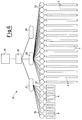
- the appliance shown in Figure 8 differs in that the light source groups positioned on the corresponding support panels 9A comprise two halogen light sources 6A.
- the translucent screen 3 is constructed in several pieces, these in the case shown being of rectangular plan shape and arranged between the opposing tubular elements 7 and 8 such that the minor sides of said screen pieces are supported by the frame 2 parallel to its major sides 7, whereas the major sides of said screen pieces are supported by curved bars 23 of T cross-section.
- the translucent screen 3 is preferably of acrylic material.
- the central control unit which controls the operation of each lamp comprises a computerized unit 25, a decoder 26, local control units 27-29 and dimmers 30 connected to the light sources 5 and 6.
- the computerized unit 25 operates on the basis of software which for example reproduces for a predetermined latitude the lighting conditions for an entire solar year of a determined climatic zone.
- the decoder 26 acts as the interface between the computerized unit 25 and the local control units 27-29 so that the signals emitted by the unit 25 can be interpreted by the local control units 27-29.
- the local control unit 27 is arranged to control the dimmer 30 of each individual incandescent lamp such as the halogen lamps.
- the local control unit 28 is arranged to control the dimmer 30 of each individual fluorescent lamp 5.
- the local control unit 23 is arranged to control the dimmer 30 of any individual capacitive discharge lamp.
- Gaskets 31 are provided between the appliance 1 and the false ceiling 21 to make the skylight simulation offered by the appliance 1 perfectly functional.
Landscapes
- Engineering & Computer Science (AREA)
- General Engineering & Computer Science (AREA)
- Physics & Mathematics (AREA)
- Spectroscopy & Molecular Physics (AREA)
- Non-Portable Lighting Devices Or Systems Thereof (AREA)
- Liquid Crystal (AREA)
- Illuminated Signs And Luminous Advertising (AREA)
Abstract
Description
- This invention relates to a lighting appliance, particularly for environments without natural light.
- Environments are known to exist, even for residential and working use, which for various reasons are without natural light.
- Artificial light is therefore used to light such environments.
- Medical research has however shown that the more a subject remains within environments lit by only artificial light, the greater is the probability of his suffering disturbances, the most frequent of which is a loss of the sense of time, which our body spontaneously assumes by virtue of the time signals implicit in natural light.
- Hence in the current state of the art the only remedy is to limit the time for which a subject remains in environments without natural light, particularly in the case of a subject particularly sensitive to such phenomena.
- The object of the present invention is to obviate the aforesaid drawbacks.
- This object is attained by a lighting appliance in accordance with the first claim.
- By providing several light sources of different colour temperature and enabling them to be powered separately, the quality of the light emitted by the appliance can be influenced such that it resembles natural light as much as possible.
- In addition the facility for varying the operating intensity of the individual light sources enables the light to be given the desired directionality through the translucent screen, in order to simulate the movement of the sun as the hour of the day varies.
- The lighting appliance is therefore able to operate in a manner similar to that of a traditional skylight when traversed by natural light, which as is well known varies during the day not only in terms of colour temperature and intensity but also in terms of direction. By preventing reflection of the single images of the light sources and favouring diffusion of the light rays emitted by said sources, the translucent screen contributes to creating the desired "skylight effect".
- The desired effect can be optimized by providing a central unit for controlling the operation of the light sources moment by moment on the basis of the type of day which it is desired to simulate, by using a predetermined software program.
- The invention is illustrated by way of non-limiting example in the figures of the accompanying drawings.
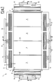
- Figure 1 is a plan view of a lighting appliance according to the invention with the reflecting screen removed in order to show the components;
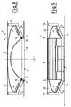
- Figure 2 is a section on the line II-II of Figure 1 complete with the reflecting screen;
- Figure 3 is a section on the line III-III of Figure 2 complete with the reflecting screen;
- Figure 4 is a side view on the major side;
- Figure 5 is a side view on the minor side;
- Figure 6 is a schematic view of the central control unit for controlling the individual light sources of the appliance;
- Figure 7 is a graph illustrating the variation in the light emission of the appliance when programmed by the central unit to simulate autumnal daylight at a latitude of about 45°;
- Figure 8 is a view corresponding to that of Figure 1 showing a further embodiment of the lighting appliance.
- Corresponding elements are indicated therein by the same reference numerals plus the letter A.
- With reference to the aforesaid figures, the lighting appliance according to the invention, indicated overall by 1, substantially comprises a
frame 2, atranslucent screen 3, a reflectingscreen 4 andlight sources frame 2, which has a structure similar to or simulating that of a traditional skylight, comprisespairs translucent screen 2 which they support. - A
first truss 11 and asecond truss 12 are fixed to the opposingtubular elements planes light sources - The
planes tubular elements false ceiling 21. - The
support trusses tube pieces tubular elements - When the
appliance 1 is installed, thetube pieces 13 abut against theoverlying floor slab 22, to which they are fixed by traditional screws, not shown. - The
tube pieces 14 can be used as handles for transporting and/or installing the appliance. The reflectingscreen 4 comprises three portions, namely twolateral portions 17 and onecentral portion 18. Thelateral portions 17 are supported by thetrusses 12 and thecentral portion 18 is supported by thetruss 11. - The
lateral portions 17 are of parabolic cross-section with their foci lying on anaxis 16 substantially parallel to the axis along which thelight sources tubular element 8. - Likewise the
central portion 18 of the reflectingscreen 4 has its foci lying onaxes 20 parallel to those along which therelative light sources tubular elements 7. - That surface of the reflecting
screen 4 facing thelight sources - In the particular case illustrated the light sources are grouped into light source groups each comprising four
fluorescent lamps 5 and at least onehalogen lamp 6. - The light source groups positioned on the
support panels 9 comprise a single halogen light source, whereas the light source groups positioned on thesupport panels 10 comprise two halogen light sources. - The appliance shown in Figure 8 differs in that the light source groups positioned on the
corresponding support panels 9A comprise twohalogen light sources 6A. - The
translucent screen 3 is constructed in several pieces, these in the case shown being of rectangular plan shape and arranged between the opposingtubular elements frame 2 parallel to itsmajor sides 7, whereas the major sides of said screen pieces are supported bycurved bars 23 of T cross-section. - The
translucent screen 3 is preferably of acrylic material. - With particular reference to Figure 6, the central control unit, indicated overall by 24, which controls the operation of each lamp comprises a
computerized unit 25, adecoder 26, local control units 27-29 anddimmers 30 connected to thelight sources - The
computerized unit 25 operates on the basis of software which for example reproduces for a predetermined latitude the lighting conditions for an entire solar year of a determined climatic zone. - In this context the term "lighting conditions" means the intensity, colour temperature and exit direction of the light leaving the skylight. The
decoder 26 acts as the interface between thecomputerized unit 25 and the local control units 27-29 so that the signals emitted by theunit 25 can be interpreted by the local control units 27-29. Thelocal control unit 27 is arranged to control thedimmer 30 of each individual incandescent lamp such as the halogen lamps. Thelocal control unit 28 is arranged to control thedimmer 30 of each individualfluorescent lamp 5. - The
local control unit 23 is arranged to control thedimmer 30 of any individual capacitive discharge lamp. -
Gaskets 31 are provided between theappliance 1 and thefalse ceiling 21 to make the skylight simulation offered by theappliance 1 perfectly functional.
Claims (13)
- A lighting appliance (1) in particular for environments without natural light, characterised by comprising the following elements in combination:- a frame (2) totally surrounding a translucent screen (3);- a reflecting screen (4) side by side with said frame (2) and said translucent screen (3);- light sources (5, 6) positioned between said frame (2) and said reflecting screen (4) along the entire extension of said frame (2) so that the emitted light beams are mixedly reflected by the reflecting screen (4) and conveyed to the outside of the appliance (1) through the translucent screen (3), said light sources (5, 6) being of different colour temperatures in terms of illumination and being electrically powerable separately in a such a manner as to enable them to provide a luminous flux of variable intensity.
- An appliance as claimed in claim 1, characterised in that said light sources (5, 6) are powered separately via a central control unit which varies their electrical quantities on the basis of the hour of the day.
- An appliance as claimed in claim 1, characterised in that the frame (2) is rectangular in plan, the translucent screen (3) being concave with opposite concavity to the reflecting screen (4).
- An appliance as claimed in claim 3, characterised in that the translucent screen (3) is formed from a plurality of screen elements of rectangular plan, the minor sides of which are supported by the frame (2) parallel to its major sides, and the major sides of which are supported by bars (23) of T cross-section parallel to the minor sides of the frame (2).
- An appliance as claimed in claim 4, characterised in that the translucent screen (3) is constructed of acrylic material.
- An appliance as claimed in claim 1, characterised in that the light sources comprise fluorescent lamps (5) and halogen lamps (6).
- An appliance as claimed in claim 6, characterised in that the fluorescent lamps (5) are arranged in several rows with their major axis parallel to the sides of the frame (2) and have a colour temperature variable between 2700 and 6000°K, the halogen lamps (6) being arranged parallel thereto in the most outer row and having a colour temperature of up to about 2600°K.
- An appliance as claimed in claim 1, characterised in that the reflecting screen (4) comprises for each side of the frame (2) a laminar element of parabolic cross-section with the axes through its foci (16, 20) substantially parallel to the axes along which the light sources (5, 6) lie, these latter being supported in planes (9, 10) incident with the plane in which the frame (2) lies.
- An appliance as claimed in claim 8, characterised in that the angle (α) between the planes (9, 10) in which the light sources (5, 6) are supported and the plane in which the frame lies is indicatively 25°.
- An appliance as claimed in claim 8, characterised in that the reflecting screen (4) is of the semi-diffusing type, ie has a semi-opaque surface.
- An appliance as claimed in claim 10, characterised in that the semi-diffusing surface is white in colour.
- An appliance as claimed in claim 3, characterised in that the length and width of the frame (2) are multiples of 60 cm.
- An appliance as claimed in claim 1, characterised in that the frame (2) comprises gaskets (31) along the tubular elements (7, 8).
Applications Claiming Priority (2)
| Application Number | Priority Date | Filing Date | Title |
|---|---|---|---|
| ITMI913197 | 1991-11-29 | ||
| ITMI913197A IT1252026B (en) | 1991-11-29 | 1991-11-29 | LIGHTING APPARATUS IN PARTICULAR FOR ENVIRONMENTS WITHOUT NATURAL LIGHT |
Publications (2)
| Publication Number | Publication Date |
|---|---|
| EP0545474A1 true EP0545474A1 (en) | 1993-06-09 |
| EP0545474B1 EP0545474B1 (en) | 1995-08-30 |
Family
ID=11361220
Family Applications (1)
| Application Number | Title | Priority Date | Filing Date |
|---|---|---|---|
| EP92203646A Expired - Lifetime EP0545474B1 (en) | 1991-11-29 | 1992-11-26 | Lighting appliance, particularly for environments without natural light |
Country Status (6)
| Country | Link |
|---|---|
| US (1) | US5285356A (en) |
| EP (1) | EP0545474B1 (en) |
| CA (1) | CA2083998C (en) |
| DE (1) | DE69204429T2 (en) |
| ES (1) | ES2078649T3 (en) |
| IT (1) | IT1252026B (en) |
Cited By (6)
| Publication number | Priority date | Publication date | Assignee | Title |
|---|---|---|---|---|
| US5577131A (en) * | 1993-05-05 | 1996-11-19 | U.S. Philips Corporation | Device for segmenting textured images and image segmentation system comprising such a device |
| GB2306636A (en) * | 1995-10-20 | 1997-05-07 | Ashley & Rock Ltd | Controlled Operation of Lamps |
| EP1323976A3 (en) * | 2001-12-23 | 2006-08-02 | Der Kluth: Decke und Licht GmbH | Lighting apparatus |
| EP1746338A1 (en) * | 2005-07-22 | 2007-01-24 | ERCO Leuchten GmbH | Luminaire |
| EP2096351A2 (en) | 2005-06-13 | 2009-09-02 | Zumbotel Lighting GmbH | Lighting assembly for supporting human optics and well-being |
| WO2017162916A1 (en) | 2016-03-23 | 2017-09-28 | Light Cognitive Oy | A lighting system, and a method of producing a light projection |
Families Citing this family (32)
| Publication number | Priority date | Publication date | Assignee | Title |
|---|---|---|---|---|
| DE19925893A1 (en) * | 1999-06-07 | 2000-12-21 | Markus Thiermeyer | Unit for producing diffused light comprises a curved reflector and at least one light source whose light reaches the objective to be illuminated via the reflector and a diffuser incorporated in the frame of the unit |
| EP1610593B2 (en) | 1999-11-18 | 2020-02-19 | Signify North America Corporation | Generation of white light with Light Emitting Diodes having different spectrum |
| AU2001289573A1 (en) * | 2000-11-20 | 2002-05-27 | Manfred Kluth | Lighting element |
| CN1653297B (en) * | 2002-05-08 | 2010-09-29 | 佛森技术公司 | High efficiency solid-state light source and methods of use and manufacture |
| US6980949B2 (en) * | 2003-03-14 | 2005-12-27 | Sonum Technologies, Inc. | Natural language processor |
| US6991029B2 (en) * | 2003-06-06 | 2006-01-31 | Orfield Laboratories, Inc. | Architectural dynamic control: intelligent environmental control and feedback system for architectural settings including offices |
| JP2008545904A (en) * | 2005-06-01 | 2008-12-18 | コーニンクレッカ フィリップス エレクトロニクス エヌ ヴィ | Fake window |
| US20070067155A1 (en) * | 2005-09-20 | 2007-03-22 | Sonum Technologies, Inc. | Surface structure generation |
| JP2009026584A (en) * | 2007-07-19 | 2009-02-05 | Okuju Co Ltd | Luminaire |
| ES2335042T3 (en) * | 2007-08-02 | 2010-03-18 | Hartmut S. Engel | LAMP. |
| US8523389B2 (en) * | 2007-12-18 | 2013-09-03 | Koninklijke Philips N.V. | Illumination system with inclined light source |
| US8021008B2 (en) * | 2008-05-27 | 2011-09-20 | Abl Ip Holding Llc | Solid state lighting using quantum dots in a liquid |
| US20100103655A1 (en) * | 2008-10-29 | 2010-04-29 | Smith Andrew N | Electronic skylight system |
| EP2863117B1 (en) * | 2009-11-09 | 2016-07-13 | LG Innotek Co., Ltd. | Lighting device |
| US8568000B2 (en) * | 2011-08-29 | 2013-10-29 | Tai-Her Yang | Annular-arranged lamp capable of backward projecting by concave sphere |
| EP3078903B1 (en) * | 2011-09-08 | 2018-04-11 | LG Innotek Co., Ltd. | Lighting module |
| WO2013061189A1 (en) | 2011-10-25 | 2013-05-02 | Koninklijke Philips Electronics N.V. | Methods and apparatus for control of illumination in an interior space |
| US9080763B2 (en) | 2012-05-17 | 2015-07-14 | GE Lighting Solutions, LLC | Edge lit luminaires for windows |
| EP3702685A1 (en) | 2012-08-28 | 2020-09-02 | Delos Living LLC | Environmental control system and method of operation such system |
| US20140071673A1 (en) * | 2012-09-11 | 2014-03-13 | Abl Ip Holding Llc | Recessed Luminaire |
| US20140177219A1 (en) * | 2012-12-20 | 2014-06-26 | Ecolite Manufacturing Co. | Low Profile Light Fixture |
| AU2015223112B2 (en) | 2014-02-28 | 2020-07-09 | Delos Living Llc | Systems, methods and articles for enhancing wellness associated with habitable environments |
| CN107251031A (en) | 2015-01-13 | 2017-10-13 | 戴尔斯生活有限责任公司 | System, method and product for monitoring and strengthening health |
| US9894729B2 (en) | 2015-12-15 | 2018-02-13 | Arborlight, Inc. | Artificial light configured for daylight emulation |
| US11338107B2 (en) | 2016-08-24 | 2022-05-24 | Delos Living Llc | Systems, methods and articles for enhancing wellness associated with habitable environments |
| DE102017000190A1 (en) | 2017-01-11 | 2018-07-12 | Osram Gmbh | Skylight assembly and method of making a skylight assembly |
| WO2019046580A1 (en) | 2017-08-30 | 2019-03-07 | Delos Living Llc | Systems, methods and articles for assessing and/or improving health and well-being |
| WO2020055872A1 (en) | 2018-09-14 | 2020-03-19 | Delos Living Llc | Systems and methods for air remediation |
| WO2020176503A1 (en) | 2019-02-26 | 2020-09-03 | Delos Living Llc | Method and apparatus for lighting in an office environment |
| US10976036B2 (en) | 2019-03-05 | 2021-04-13 | Abl Ip Holding Llc | Rotatable linear downlight |
| US11898898B2 (en) | 2019-03-25 | 2024-02-13 | Delos Living Llc | Systems and methods for acoustic monitoring |
| USD979826S1 (en) | 2020-02-25 | 2023-02-28 | Abl Ip Holding Llc | Luminaire |
Citations (4)
| Publication number | Priority date | Publication date | Assignee | Title |
|---|---|---|---|---|
| US3180978A (en) * | 1962-07-20 | 1965-04-27 | Dynamic Instr Corp | Lighting systems for dwellings |
| FR2151121A1 (en) * | 1971-09-04 | 1973-04-13 | Philips Nv | |
| WO1985001566A1 (en) * | 1983-10-03 | 1985-04-11 | Heinrich Wendel | Reflector device |
| DE3916997A1 (en) * | 1988-06-16 | 1989-12-21 | Tetsuhiro Kano | Illumination device |
Family Cites Families (9)
| Publication number | Priority date | Publication date | Assignee | Title |
|---|---|---|---|---|
| US1326393A (en) * | 1919-02-24 | 1919-12-30 | Fernand E D Humy | Electric-light fixture. |
| US1784171A (en) * | 1927-05-14 | 1930-12-09 | Bertling Herbert | Artificial lighting having a daylight effect |
| US2725461A (en) * | 1952-11-12 | 1955-11-29 | Analite Corp | Artificial daylight lamp |
| US3093319A (en) * | 1959-11-26 | 1963-06-11 | Gamain Charles Henri Alfred | Apparatus for producing artificial daylight |
| GB1138878A (en) * | 1966-09-09 | 1969-01-01 | British Lighting Ind Ltd | Artificial sun-bathing enclosure |
| US3517180A (en) * | 1969-04-21 | 1970-06-23 | Zinovia Semotan | Artificial lighting system |
| US4423469A (en) * | 1981-07-21 | 1983-12-27 | Dset Laboratories, Inc. | Solar simulator and method |
| US4933813A (en) * | 1986-04-14 | 1990-06-12 | Berger Daniel S | Sunlight simulator |
| US5060118A (en) * | 1989-04-06 | 1991-10-22 | Frank A. Arone | Apparatus for daylight color duplication |
-
1991
- 1991-11-29 IT ITMI913197A patent/IT1252026B/en active IP Right Grant
-
1992
- 1992-11-23 US US07/980,340 patent/US5285356A/en not_active Expired - Lifetime
- 1992-11-26 ES ES92203646T patent/ES2078649T3/en not_active Expired - Lifetime
- 1992-11-26 DE DE69204429T patent/DE69204429T2/en not_active Expired - Lifetime
- 1992-11-26 EP EP92203646A patent/EP0545474B1/en not_active Expired - Lifetime
- 1992-11-27 CA CA002083998A patent/CA2083998C/en not_active Expired - Fee Related
Patent Citations (4)
| Publication number | Priority date | Publication date | Assignee | Title |
|---|---|---|---|---|
| US3180978A (en) * | 1962-07-20 | 1965-04-27 | Dynamic Instr Corp | Lighting systems for dwellings |
| FR2151121A1 (en) * | 1971-09-04 | 1973-04-13 | Philips Nv | |
| WO1985001566A1 (en) * | 1983-10-03 | 1985-04-11 | Heinrich Wendel | Reflector device |
| DE3916997A1 (en) * | 1988-06-16 | 1989-12-21 | Tetsuhiro Kano | Illumination device |
Cited By (8)
| Publication number | Priority date | Publication date | Assignee | Title |
|---|---|---|---|---|
| US5577131A (en) * | 1993-05-05 | 1996-11-19 | U.S. Philips Corporation | Device for segmenting textured images and image segmentation system comprising such a device |
| GB2306636A (en) * | 1995-10-20 | 1997-05-07 | Ashley & Rock Ltd | Controlled Operation of Lamps |
| EP1323976A3 (en) * | 2001-12-23 | 2006-08-02 | Der Kluth: Decke und Licht GmbH | Lighting apparatus |
| EP2096351A2 (en) | 2005-06-13 | 2009-09-02 | Zumbotel Lighting GmbH | Lighting assembly for supporting human optics and well-being |
| EP2096351A3 (en) * | 2005-06-13 | 2009-09-09 | Zumbotel Lighting GmbH | Lighting assembly for supporting human optics and well-being |
| EP1746338A1 (en) * | 2005-07-22 | 2007-01-24 | ERCO Leuchten GmbH | Luminaire |
| US7497587B2 (en) | 2005-07-22 | 2009-03-03 | Erco Gmbh | Lamp |
| WO2017162916A1 (en) | 2016-03-23 | 2017-09-28 | Light Cognitive Oy | A lighting system, and a method of producing a light projection |
Also Published As
| Publication number | Publication date |
|---|---|
| ES2078649T3 (en) | 1995-12-16 |
| CA2083998C (en) | 2004-03-16 |
| US5285356A (en) | 1994-02-08 |
| DE69204429T2 (en) | 1996-05-02 |
| EP0545474B1 (en) | 1995-08-30 |
| IT1252026B (en) | 1995-05-27 |
| CA2083998A1 (en) | 1993-05-30 |
| DE69204429D1 (en) | 1995-10-05 |
| ITMI913197A0 (en) | 1991-11-29 |
| ITMI913197A1 (en) | 1993-05-29 |
Similar Documents
| Publication | Publication Date | Title |
|---|---|---|
| US5285356A (en) | Lighting appliance, particularly for environments without natural light | |
| US4091441A (en) | Full-spectrum luminaire | |
| US4557565A (en) | Beam sunlighting device for building interiors | |
| US4336576A (en) | Lighting apparatus | |
| US5020252A (en) | Illuminated sign system | |
| FI101586B (en) | The method for adjusting the illumination intensity of the sum light is according to the external light | |
| US20100039799A1 (en) | Combined daylight electric light fixture for buildings using electrochromic and mechanical methods | |
| EP0151850A3 (en) | Reflector systems for lighting fixtures and methods of installing such system | |
| NO168387C (en) | INDIRECT MIRROR LIGHTING | |
| US8569977B2 (en) | Lighting system combining natural and artificial light | |
| US3009054A (en) | Prismatic lighting fixture | |
| US2990470A (en) | Reflecting fluorescent light fixture | |
| US4453201A (en) | Electrically illuminated cross | |
| US20040095771A1 (en) | Reduced shadow system for illuminating an activity area | |
| CH697541B1 (en) | Luminaire for use as pendant luminaire mounted in ceiling of room of building for e.g. emergency lighting, has light-reflection/light-distribution units e.g. diffuser, designed for reflecting and/or distributing light produced by LEDs | |
| JPH03226903A (en) | Underground lighting device imitating natural light | |
| JPH1012019A (en) | Guided sunlight system | |
| JP4540789B2 (en) | LIGHTING DEVICE, ROOM EQUIPPED WITH THE SAME, AND LIGHTING METHOD | |
| JP2775218B2 (en) | Atrium lighting equipment | |
| JPH04212035A (en) | Irradiation device of artificial sky | |
| KR100841255B1 (en) | A circumferential lighting apparatus for roofs with curved surfaces | |
| Carpenter et al. | Further aspects of the artificial illumination of plant growth chambers | |
| JP2793080B2 (en) | Lighting equipment | |
| Cockram et al. | Lighting of hospital circulation spaces which are open to bed bays | |
| DE20205820U1 (en) | Signage |
Legal Events
| Date | Code | Title | Description |
|---|---|---|---|
| PUAI | Public reference made under article 153(3) epc to a published international application that has entered the european phase |
Free format text: ORIGINAL CODE: 0009012 |
|
| AK | Designated contracting states |
Kind code of ref document: A1 Designated state(s): CH DE ES FR GB LI NL SE |
|
| 17P | Request for examination filed |
Effective date: 19930618 |
|
| 17Q | First examination report despatched |
Effective date: 19940609 |
|
| GRAA | (expected) grant |
Free format text: ORIGINAL CODE: 0009210 |
|
| AK | Designated contracting states |
Kind code of ref document: B1 Designated state(s): CH DE ES FR GB LI NL SE |
|
| PG25 | Lapsed in a contracting state [announced via postgrant information from national office to epo] |
Ref country code: NL Free format text: LAPSE BECAUSE OF FAILURE TO SUBMIT A TRANSLATION OF THE DESCRIPTION OR TO PAY THE FEE WITHIN THE PRESCRIBED TIME-LIMIT Effective date: 19950830 |
|
| REF | Corresponds to: |
Ref document number: 69204429 Country of ref document: DE Date of ref document: 19951005 |
|
| PG25 | Lapsed in a contracting state [announced via postgrant information from national office to epo] |
Ref country code: SE Effective date: 19951130 |
|
| REG | Reference to a national code |
Ref country code: ES Ref legal event code: FG2A Ref document number: 2078649 Country of ref document: ES Kind code of ref document: T3 |
|
| ET | Fr: translation filed | ||
| NLV1 | Nl: lapsed or annulled due to failure to fulfill the requirements of art. 29p and 29m of the patents act | ||
| PLBE | No opposition filed within time limit |
Free format text: ORIGINAL CODE: 0009261 |
|
| STAA | Information on the status of an ep patent application or granted ep patent |
Free format text: STATUS: NO OPPOSITION FILED WITHIN TIME LIMIT |
|
| 26N | No opposition filed | ||
| REG | Reference to a national code |
Ref country code: GB Ref legal event code: IF02 |
|
| REG | Reference to a national code |
Ref country code: CH Ref legal event code: PCAR Free format text: AMMANN PATENTANWAELTE AG BERN;SCHWARZTORSTRASSE 31;3001 BERN (CH) |
|
| PGFP | Annual fee paid to national office [announced via postgrant information from national office to epo] |
Ref country code: CH Payment date: 20091113 Year of fee payment: 18 Ref country code: ES Payment date: 20091201 Year of fee payment: 18 Ref country code: DE Payment date: 20091119 Year of fee payment: 18 |
|
| PGFP | Annual fee paid to national office [announced via postgrant information from national office to epo] |
Ref country code: FR Payment date: 20091123 Year of fee payment: 18 Ref country code: GB Payment date: 20091125 Year of fee payment: 18 |
|
| REG | Reference to a national code |
Ref country code: CH Ref legal event code: PL |
|
| GBPC | Gb: european patent ceased through non-payment of renewal fee |
Effective date: 20101126 |
|
| PG25 | Lapsed in a contracting state [announced via postgrant information from national office to epo] |
Ref country code: LI Free format text: LAPSE BECAUSE OF NON-PAYMENT OF DUE FEES Effective date: 20101130 Ref country code: CH Free format text: LAPSE BECAUSE OF NON-PAYMENT OF DUE FEES Effective date: 20101130 |
|
| REG | Reference to a national code |
Ref country code: FR Ref legal event code: ST Effective date: 20110801 |
|
| REG | Reference to a national code |
Ref country code: DE Ref legal event code: R119 Ref document number: 69204429 Country of ref document: DE Effective date: 20110601 Ref country code: DE Ref legal event code: R119 Ref document number: 69204429 Country of ref document: DE Effective date: 20110531 |
|
| PG25 | Lapsed in a contracting state [announced via postgrant information from national office to epo] |
Ref country code: DE Free format text: LAPSE BECAUSE OF NON-PAYMENT OF DUE FEES Effective date: 20110531 |
|
| PG25 | Lapsed in a contracting state [announced via postgrant information from national office to epo] |
Ref country code: FR Free format text: LAPSE BECAUSE OF NON-PAYMENT OF DUE FEES Effective date: 20101130 |
|
| PG25 | Lapsed in a contracting state [announced via postgrant information from national office to epo] |
Ref country code: GB Free format text: LAPSE BECAUSE OF NON-PAYMENT OF DUE FEES Effective date: 20101126 |
|
| REG | Reference to a national code |
Ref country code: ES Ref legal event code: FD2A Effective date: 20120110 |
|
| PG25 | Lapsed in a contracting state [announced via postgrant information from national office to epo] |
Ref country code: ES Free format text: LAPSE BECAUSE OF NON-PAYMENT OF DUE FEES Effective date: 20101127 |