EP0544961B2 - Weatherstrip for vehicle closures and method for its manufacture - Google Patents
Weatherstrip for vehicle closures and method for its manufacture Download PDFInfo
- Publication number
- EP0544961B2 EP0544961B2 EP91403244A EP91403244A EP0544961B2 EP 0544961 B2 EP0544961 B2 EP 0544961B2 EP 91403244 A EP91403244 A EP 91403244A EP 91403244 A EP91403244 A EP 91403244A EP 0544961 B2 EP0544961 B2 EP 0544961B2
- Authority
- EP
- European Patent Office
- Prior art keywords
- shaped portion
- length
- tubular
- tubular element
- section
- Prior art date
- Legal status (The legal status is an assumption and is not a legal conclusion. Google has not performed a legal analysis and makes no representation as to the accuracy of the status listed.)
- Expired - Lifetime
Links
Images

Classifications
-
- E—FIXED CONSTRUCTIONS
- E06—DOORS, WINDOWS, SHUTTERS, OR ROLLER BLINDS IN GENERAL; LADDERS
- E06B—FIXED OR MOVABLE CLOSURES FOR OPENINGS IN BUILDINGS, VEHICLES, FENCES OR LIKE ENCLOSURES IN GENERAL, e.g. DOORS, WINDOWS, BLINDS, GATES
- E06B7/00—Special arrangements or measures in connection with doors or windows
- E06B7/16—Sealing arrangements on wings or parts co-operating with the wings
- E06B7/22—Sealing arrangements on wings or parts co-operating with the wings by means of elastic edgings, e.g. elastic rubber tubes; by means of resilient edgings, e.g. felt or plush strips, resilient metal strips
- E06B7/23—Plastic, sponge rubber, or like strips or tubes
- E06B7/2314—Plastic, sponge rubber, or like strips or tubes characterised by the material
-
- B—PERFORMING OPERATIONS; TRANSPORTING
- B60—VEHICLES IN GENERAL
- B60J—WINDOWS, WINDSCREENS, NON-FIXED ROOFS, DOORS, OR SIMILAR DEVICES FOR VEHICLES; REMOVABLE EXTERNAL PROTECTIVE COVERINGS SPECIALLY ADAPTED FOR VEHICLES
- B60J10/00—Sealing arrangements
- B60J10/15—Sealing arrangements characterised by the material
- B60J10/16—Sealing arrangements characterised by the material consisting of two or more plastic materials having different physical or chemical properties
-
- B—PERFORMING OPERATIONS; TRANSPORTING
- B60—VEHICLES IN GENERAL
- B60J—WINDOWS, WINDSCREENS, NON-FIXED ROOFS, DOORS, OR SIMILAR DEVICES FOR VEHICLES; REMOVABLE EXTERNAL PROTECTIVE COVERINGS SPECIALLY ADAPTED FOR VEHICLES
- B60J10/00—Sealing arrangements
- B60J10/15—Sealing arrangements characterised by the material
- B60J10/18—Sealing arrangements characterised by the material provided with reinforcements or inserts
-
- B—PERFORMING OPERATIONS; TRANSPORTING
- B60—VEHICLES IN GENERAL
- B60J—WINDOWS, WINDSCREENS, NON-FIXED ROOFS, DOORS, OR SIMILAR DEVICES FOR VEHICLES; REMOVABLE EXTERNAL PROTECTIVE COVERINGS SPECIALLY ADAPTED FOR VEHICLES
- B60J10/00—Sealing arrangements
- B60J10/20—Sealing arrangements characterised by the shape
- B60J10/21—Sealing arrangements characterised by the shape having corner parts or bends
-
- B—PERFORMING OPERATIONS; TRANSPORTING
- B60—VEHICLES IN GENERAL
- B60J—WINDOWS, WINDSCREENS, NON-FIXED ROOFS, DOORS, OR SIMILAR DEVICES FOR VEHICLES; REMOVABLE EXTERNAL PROTECTIVE COVERINGS SPECIALLY ADAPTED FOR VEHICLES
- B60J10/00—Sealing arrangements
- B60J10/20—Sealing arrangements characterised by the shape
- B60J10/22—Sealing arrangements characterised by the shape having varying cross-section in the longitudinal direction
-
- B—PERFORMING OPERATIONS; TRANSPORTING
- B60—VEHICLES IN GENERAL
- B60J—WINDOWS, WINDSCREENS, NON-FIXED ROOFS, DOORS, OR SIMILAR DEVICES FOR VEHICLES; REMOVABLE EXTERNAL PROTECTIVE COVERINGS SPECIALLY ADAPTED FOR VEHICLES
- B60J10/00—Sealing arrangements
- B60J10/20—Sealing arrangements characterised by the shape
- B60J10/24—Sealing arrangements characterised by the shape having tubular parts
- B60J10/244—Sealing arrangements characterised by the shape having tubular parts inflatable or deflatable
-
- B—PERFORMING OPERATIONS; TRANSPORTING
- B60—VEHICLES IN GENERAL
- B60J—WINDOWS, WINDSCREENS, NON-FIXED ROOFS, DOORS, OR SIMILAR DEVICES FOR VEHICLES; REMOVABLE EXTERNAL PROTECTIVE COVERINGS SPECIALLY ADAPTED FOR VEHICLES
- B60J10/00—Sealing arrangements
- B60J10/80—Sealing arrangements specially adapted for opening panels, e.g. doors
-
- Y—GENERAL TAGGING OF NEW TECHNOLOGICAL DEVELOPMENTS; GENERAL TAGGING OF CROSS-SECTIONAL TECHNOLOGIES SPANNING OVER SEVERAL SECTIONS OF THE IPC; TECHNICAL SUBJECTS COVERED BY FORMER USPC CROSS-REFERENCE ART COLLECTIONS [XRACs] AND DIGESTS
- Y10—TECHNICAL SUBJECTS COVERED BY FORMER USPC
- Y10T—TECHNICAL SUBJECTS COVERED BY FORMER US CLASSIFICATION
- Y10T156/00—Adhesive bonding and miscellaneous chemical manufacture
- Y10T156/10—Methods of surface bonding and/or assembly therefor
- Y10T156/1002—Methods of surface bonding and/or assembly therefor with permanent bending or reshaping or surface deformation of self sustaining lamina
- Y10T156/1043—Subsequent to assembly
Definitions
- the present invention relates to a seal, for framing an opening of a automobile bodywork or the like.
- the invention has also relates to a process for manufacturing this seal.
- joints for framing automobile door or trunk include usually a U-shaped section forming clamp, of a thermoplastic material provided with a metal frame, this profile being intended to cover a protruding part of the frame for join the seal, and an element elastically deformable tubular, generally made of cellular material, which is attached to the profile forming a clamp and which is intended to be compressed between the frame and the corresponding mobile element automotive to seal.
- the clamp profile and the tubular element can be coextruded from the same head extrusion. They can also be made separately and then be united to each other by collage.
- the element tubular which is of relatively large volume and whose cross section generally has a complex profile, tends, on the one hand, to form folds all the more marked as the curvature coaching is more important, on the other hand, offset with respect to the profile in the form of clamp and deform.
- the present invention aims to remedy a different way to this disadvantage by not joining not locally the profile forming a clamp and the tubular sealing element, at the time of the assembly of the elements of the seal, and by giving the portion of this tubular element not attached to the profile a length slightly greater than that of the corresponding portion of the profiled, this portion then being assembled by collage.
- this part of the seal in the corner of the frame of door which has a radius of curvature strongly marked, the tubular sealing element will have a degree of freedom with respect to the profile forming clamp and it will be able to occupy itself of the most favorable position, without folds, sagging or other deformations, during its installation on the frame, by its local offset in the angle relative to the clamp member.
- the subject of the invention is therefore a seal for framing an opening an automobile body, this joint comprising a reinforced profile forming a U-section clamp, made of a thermoplastic material, and an element tubular sealing in a deformable material elastically, which adheres laterally to the surface external of the U-shaped section,
- a seal for framing an opening an automobile body this joint comprising a reinforced profile forming a U-section clamp, made of a thermoplastic material, and an element tubular sealing in a deformable material elastically, which adheres laterally to the surface external of the U-shaped section,
- the tubular sealing element has a length greater than that of the part of the profile, to which it adheres, the portion of the tubular element of length greater than that of the part of the profile having been made non-adherent to said corresponding part of the profile by elevation, being offset laterally with respect to it, then having been glued to this profile.
- the tubular profile will therefore best fit the corresponding shape of the frame angle door that the seal is intended to equip.
- the invention also relates to a method of manufacturing such a seal for framing the opening of an automobile body, this joint comprising a reinforced profile forming U-section pliers, of a thermoplastic material, and a tubular sealing element, in an elastically deformable material, which adheres laterally to the external surface of the section profile U-shaped, this process being of the type in which the U-section profile and tubular sealing element are made separately and are assembled by bonding, this process being characterized in that that during the bonding phase, the profile to U-section and tubular sealing element are separated according to at least part of their length by a shim opposing their joining in this location, this wedge being arranged in such a way that the tubular element forms a bridge over the length of the profile greater than that of the corresponding part of the profile, this wedge then being released from the joint, and the previously separated parts being then assembled by gluing.
- the shim used can also used to offset laterally with respect to the profile the portion of the tubular member that does not adhere to this one.
- the part of the element tubular longer than the profile can be reinforced internally, either by a tubular insert, for example made of cellular material, either by plastic foam polymerized in situ. This part may also suffer permanent hot deformation so as to locally increase its cross section.
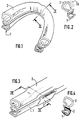
- the seal for opening frame of an automobile body which is represented in Figures 1 and 2 includes, so known, a profile 1 forming a clamp, with cross section U-shaped, which has a metal frame, also U-shaped, embedded in the mass of the polymer constituting the profile, of the polychloride vinyl for example.
- This profile 1 is intended to style and pinch a protruding edge of the body opening to be fitted and, on the face external of the U branch intended to be turned towards the outside of the body is stuck an element sealing tube 2, intended to be compressed between the opening frame and the body mobile closing this opening, one door per example.
- the tubular element 2 is made of a material elastically deformable and preferably in cellular rubber.
- the present invention proposes, during the bonding phase of the tubular element 2 on profile 1, to interpose them at the location corresponding to the angle of the frame door to be fitted, a thickness 3 wedge, formed for example, as shown in Figures 3 and 4, by pliers or a clip suitable for styling transversely the profile over a certain length (see figures 3 and 4). Due to the presence of the hold 3, the profile 1 and the tubular element 2 will not adhere to each other at this location and the unglued part of element 2 will be raised relative to the corresponding part of the profile 1, thus having a length greater than that of this part. These two parts will then joined together by gluing.
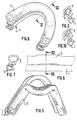
- the seal thus produced can be folded with strong curvature, without the element tubular 2 creases, collapses or deforms in any way, in the portion angle subject to curvature (see Figures 5 to 7), due to the excess length of element 2 by compared to profile 1.
- Element 2 can thus keep a tubular shape not affected by the curvature and occupy the most appropriate position in the corner.
- wedge 3 used during the bonding phase can also have a shape such that it offset laterally element 2 with respect to profile 1, to favor the placement of this element 2 in the angle of door frame.
- an insert can be accommodated tubular 4 in the open portion of the element tubular 2, in order to increase its resistance in the curved part.
- the invention provides so a simple and effective way to keep to the tubular sealing elements the shape which is theirs even in parts with very curvature marked with framing of bodywork openings of automobiles.
Abstract
Description
La présente invention concerne un joint d'étanchéite, pour encadrement d'une ouverture d'une carrosserie d'automobile ou similaire. L'invention a également pour objet un procédé de fabrication de ce joint d'étanchéité.The present invention relates to a seal, for framing an opening of a automobile bodywork or the like. The invention has also relates to a process for manufacturing this seal.
On sait que de tels joints pour encadrements de porte ou de coffre d'automobile comprennent habituellement un profilé à section en U formant pince, en une matière thermoplastique munie d'une armature métallique, ce profilé étant destiné à coiffer une partie saillante de l'encadrement pour en rendre solidaire le joint d'étanchéité, et un élément tubulaire déformable élastiquement, généralement en un matériau cellulaire, qui est attenant au profilé formant pince et qui est destiné à être comprimé entre l'encadrement et l'élément mobile correspondant de l'automobile pour assurer l'étanchéité.We know that such joints for framing automobile door or trunk include usually a U-shaped section forming clamp, of a thermoplastic material provided with a metal frame, this profile being intended to cover a protruding part of the frame for join the seal, and an element elastically deformable tubular, generally made of cellular material, which is attached to the profile forming a clamp and which is intended to be compressed between the frame and the corresponding mobile element automotive to seal.
Le profilé formant pince et l'élément tubulaire peuvent être coextrudés à partir d'une même tête d'extrusion. Ils peuvent aussi être fabriqués séparément et être ensuite rendus solidaires l'un de l'autre par collage.The clamp profile and the tubular element can be coextruded from the same head extrusion. They can also be made separately and then be united to each other by collage.
C'est à ce dernier processus de fabrication que s'intéresse la présente invention et elle vise à remédier aux inconvénients rencontrés lors de la mise en place de ces joints d'étanchéité sur des encadrements d'ouverture de carrosserie présentant dans certains angles des courbures très accentuées.It is to this last manufacturing process that is interested in the present invention and it aims to remedy the drawbacks encountered during the placement of these seals on body opening frames presenting in certain angles very marked curvatures.
En effet, en de tels emplacements, l'élément tubulaire, qui est d'un volume relativement important et dont la section transversale a généralement un profil complexe, a tendance, d'une part, à former des plis d'autant plus accusés que la courbure de l'encadrement est plus importante, d'autre part, à se décaler par rapport au profilé en forme de pince et à se déformer.Indeed, in such locations, the element tubular, which is of relatively large volume and whose cross section generally has a complex profile, tends, on the one hand, to form folds all the more marked as the curvature coaching is more important, on the other hand, offset with respect to the profile in the form of clamp and deform.
Cet inconvénient est bien connu dans la technique (voir les brevets et demandes de brevet français n° FR-A-2 247 341, FR-A-2 133 107, FR-A-2 469 321 et FR-A-2 624 191 de la Demanderesse) et l'on a proposé diverses solutions à ce problème, mais elles sont toutes relativement compliquées et coûteuses, car elles impliquent la plupart du temps que l'on rapporte un excès local de matière sur la partie du joint située dans l'angle de l'encadrement.This drawback is well known in the art (see French patents and patent applications n ° FR-A-2 247 341, FR-A-2 133 107, FR-A-2 469 321 and FR-A-2 624 191 by the Applicant) and we have proposed various solutions to this problem, but they are all relatively complicated and expensive, because they involve most of the time that we report a local excess of matter on the part of the joint located in the corner of the frame.
La présente invention vise à remédier d'une manière différente à cet inconvénient en ne solidarisant pas localement le profilé formant pince et l'élément tubulaire d'étanchéité, au moment de l'assemblage des éléments du joint d'étanchéité, et en donnant à la portion de cet élément tubulaire non solidaire du profilé une longueur légèrement supérieure à celle de la portion correspondante du profilé, cette portion étant ensuite assemblée par collage. De cette manière, en disposant cette partie du joint d'étanchéité dans l'angle de l'encadrement de porte qui a un rayon de courbure fortement marqué, l'élément tubulaire d'étanchéité disposera d'un degré de liberté par rapport au profilé formant pince et il pourra ainsi occuper de lui-même la position la plus favorable, sans plis, affaissements ou autres déformations, lors de sa mise en place sur l'encadrement, par son décalage local dans l'angle par rapport à l'élément formant pince.The present invention aims to remedy a different way to this disadvantage by not joining not locally the profile forming a clamp and the tubular sealing element, at the time of the assembly of the elements of the seal, and by giving the portion of this tubular element not attached to the profile a length slightly greater than that of the corresponding portion of the profiled, this portion then being assembled by collage. In this way, by arranging this part of the seal in the corner of the frame of door which has a radius of curvature strongly marked, the tubular sealing element will have a degree of freedom with respect to the profile forming clamp and it will be able to occupy itself of the most favorable position, without folds, sagging or other deformations, during its installation on the frame, by its local offset in the angle relative to the clamp member.
L'invention a par conséquent pour objet un joint d'étanchéité pour encadrement d'une ouverture d'une carrosserie d'automobile, ce joint comprenant un profilé armé formant pince à section en U, en un matériau thermoplastique, et un élément tubulaire d'étanchéité en un matériau déformable élastiquement, qui adhère latéralement à la surface externe du profilé à section en U, (Joint du type divulgué, par exemple, dans l'un quelconque des documents précités, caractérisé en ce que, suivant une partie au moins de sa longueur, correspondant à l'emplacement d'un angle de l'encadrement d'ouverture à équiper, l'élément tubulaire d'étanchéité présente une longueur supérieure à celle de la partie du profilé, auquel il adhère, la portion de l'élément tubulaire de longeur supérieure à celle de la partie correspondante du profilé ayant été rendue non adhérente à ladite partie correspondante du profilé par surélévation, en étant décalée latéralement par rapport à celui-ci, puis ayant été collée sur ce profilé. The subject of the invention is therefore a seal for framing an opening an automobile body, this joint comprising a reinforced profile forming a U-section clamp, made of a thermoplastic material, and an element tubular sealing in a deformable material elastically, which adheres laterally to the surface external of the U-shaped section, (Joint type disclosed, for example, in any of aforementioned documents, characterized in that, according to at least part of its length, corresponding at the location of a corner of the opening frame to be fitted, the tubular sealing element has a length greater than that of the part of the profile, to which it adheres, the portion of the tubular element of length greater than that of the part of the profile having been made non-adherent to said corresponding part of the profile by elevation, being offset laterally with respect to it, then having been glued to this profile.
Le profilé tubulaire épousera ainsi au mieux la forme correspondante de l'angle de l'encadrement de porte que le joint est destiné à équiper.The tubular profile will therefore best fit the corresponding shape of the frame angle door that the seal is intended to equip.
L'invention a également pour objet un procédé de fabrication d'un tel joint d'étanchéité pour encadrement d'une ouverture d'une carrosserie d'automobile, ce joint comprenant un profilé armé formant pince à section en U, en un matériau thermoplastique, et un élément tubulaire d'étanchéité, en un matériau déformable élastiquement, qui adhère latéralement à la surface externe du profilé à section en U, ce procédé étant du type dans lequel le profilé à section en U et l'élément tubulaire d'étanchéité sont réalisés séparément et sont assemblés par collage, ce procédé étant caractérisé en ce que, pendant la phase de collage, le profilé à section en U et l'élément tubulaire d'étanchéité sont séparés suivant une partie au moins de leur longueur par une cale d'épaisseur s'opposant à leur solidarisation en cet emplacement, cette cale étant disposée de façon telle que l'élément tubulaire forme au-dessus du profilé un pont d'une longueur supérieure à celle de la partie correspondante du profilé, cette cale étant ensuite dégagée du joint, et les parties précédemment séparées étant alors assemblées par collage.The invention also relates to a method of manufacturing such a seal for framing the opening of an automobile body, this joint comprising a reinforced profile forming U-section pliers, of a thermoplastic material, and a tubular sealing element, in an elastically deformable material, which adheres laterally to the external surface of the section profile U-shaped, this process being of the type in which the U-section profile and tubular sealing element are made separately and are assembled by bonding, this process being characterized in that that during the bonding phase, the profile to U-section and tubular sealing element are separated according to at least part of their length by a shim opposing their joining in this location, this wedge being arranged in such a way that the tubular element forms a bridge over the length of the profile greater than that of the corresponding part of the profile, this wedge then being released from the joint, and the previously separated parts being then assembled by gluing.
La cale d'épaisseur utilisée pourra également servir à décaler latéralement par rapport au profilé la portion de l'élément tubulaire qui n'adhère pas à celui-ci. The shim used can also used to offset laterally with respect to the profile the portion of the tubular member that does not adhere to this one.
Ce procédé est donc très facile à mettre en oeuvre et l'invention permet ainsi de remédier de façon simple et très peu coûteuse aux inconvénients de la technique antérieure rappelés ci-dessus.This process is therefore very easy to implement. work and the invention thus makes it possible to remedy simple and very inexpensive way to drawbacks of the prior art recalled above.
De façon connue en soi, la partie de l'élément tubulaire de longueur supérieure à celle du profilé pourra être renforcée intérieurement, soit par un insert tubulaire, par exemple en un matériau cellulaire, soit par une mousse de matière plastique polymérisée in situ. Cette partie pourra aussi subir une déformation permanente à chaud de manière à accroítre localement sa section transversale.In a manner known per se, the part of the element tubular longer than the profile can be reinforced internally, either by a tubular insert, for example made of cellular material, either by plastic foam polymerized in situ. This part may also suffer permanent hot deformation so as to locally increase its cross section.
Les dessins annexés, qui n'ont pas de caractère
limitatif, illustrent diverses formes de mise en
oeuvre de l'invention. Sur ces dessins :
Le joint d'étanchéité pour encadrement d'ouverture
d'une carrosserie d'automobile qui est représenté
sur les figures 1 et 2 comprend, de façon
connue, un profilé 1 formant pince, à section transversale
en U, qui comporte une armature métallique,
également à section en U, noyée dans la
masse du polymère constituant le profilé, du polychlorure
de vinyle par exemple. Ce profilé 1 est
destiné à coiffer et pincer un bord saillant de
l'ouverture de carrosserie à équiper et, sur la face
externe de la branche du U destinée à être tournée
vers l'extérieur de la carrosserie est collé un élément
tubulaire d'étanchéité 2, destiné à être comprimé
entre l'encadrement de l'ouverture et l'organe
mobile obturant cette ouverture, une porte par
exemple. L'élément tubulaire 2 est en un matériau
élastiquement déformable et, de préférence, en
caoutchouc cellulaire.The seal for opening frame
of an automobile body which is represented
in Figures 1 and 2 includes, so
known, a profile 1 forming a clamp, with cross section
U-shaped, which has a metal frame,
also U-shaped, embedded in the
mass of the polymer constituting the profile, of the polychloride
vinyl for example. This profile 1 is
intended to style and pinch a protruding edge of
the body opening to be fitted and, on the face
external of the U branch intended to be turned
towards the outside of the body is stuck an
Comme on le voit sur les figures 1 et 2, lorsqu'un
tel joint est replié fortement, par exemple
pour épouser la forme d'un encadrement de porte
dont un angle a une courbure accusée, l'élément
tubulaire 2 se plisse dans l'angle et a tendance à
s'affaisser par rapport à la position 2a qui devrait
être la sienne (position représentée en traits interrompus
sur la figure 2).As can be seen in FIGS. 1 and 2, when such a seal is folded back strongly, for example to match the shape of a door frame whose angle has a marked curvature, the
C'est à cet inconvénient que vise à remédier la
présente invention et, dans ce but, elle propose,
pendant la phase de collage de l'élément tubulaire
2 sur le profilé 1, d'interposer entre eux, à l'emplacement
correspondant à l'angle de l'encadrement
de porte à équiper, une cale d'épaisseur 3, formée
par exemple, comme représenté sur les figures 3
et 4, par une pince ou un clip apte à coiffer
transversalement le profilé sur une certaine longueur
(voir figures 3 et 4). Du fait de la présence
de la cale 3, le profilé 1 et l'élément tubulaire 2
n'adhéreront pas l'un à l'autre à cet emplacement
et la partie non collée de l'élément 2 sera surélevée
par rapport à la partie correspondante du profilé
1, en ayant ainsi une longueur supérieure à celle
de cette partie. Ces deux parties seront ensuite
assemblées entre elles par collage.It is to this disadvantage that the
present invention and, for this purpose, it proposes,
during the bonding phase of the
Comme on Te voit sur les figures 5 à 14, le
joint d'étanchéité ainsi réalisé peut être replié avec
une forte courbure, sans pour autant que l'élément
tubulaire 2 se plisse, s'affaisse ou se déforme
d'une quelconque façon, dans la portion
d'angle soumise à la courbure (voir figures 5 à 7),
du fait de l'excès de longueur de l'élément 2 par
rapport au profilé 1. L'élément 2 peut ainsi conserver
une forme tubulaire non affectée par la courbure
et occuper dans l'angle la position la plus appropriée.
Ainsi qu'il a été indiqué ci-dessus, la cale 3
utilisée pendant la phase de collage peut d'ailleurs
avoir une forme telle qu'elle déporte latéralement
l'élément 2 par rapport au profilé 1, pour favoriser
la mise en place de cet élément 2 dans l'angle de
l'encadrement de porte.As you see in Figures 5 to 14, the
seal thus produced can be folded with
strong curvature, without the element
tubular 2 creases, collapses or deforms
in any way, in the portion
angle subject to curvature (see Figures 5 to 7),
due to the excess length of
Après retrait de la cale 3, les parties non
solidaires du profilé 1 et de l'élément 2 seront
assemblées par collage de leurs portions d'angle.After removal of wedge 3, the parts not
integral with profile 1 and
Pour accroítre la résistance de l'élément tubulaire
2 à la déformation dans la portion d'angle de
l'encadrement de porte, avant de le rendre solidaire
du profilé 1, différents moyens pourront être
utilisés.To increase the resistance of the
On peut simplement, comme représenté sur
les figures 8 et 9, loger de façon connue dans le
tube 2, en cet emplacement, un insert tubulaire 4,
par exemple en un matériau cellulaire.We can simply, as shown on
Figures 8 and 9, house in a known manner in the
On peut aussi introduire une résine de matière
plastique 7 dans la partie de l'élément tubulaire 2
destinée à être coudée (figure 10) et provoquer
ensuite la polymérisation et éventuellement l'expansion
in situ de cette résine.You can also introduce a material resin
plastic 7 in the part of the
Enfin, comme illustré par les figures 11 à 14,
où le profilé 1 est représenté en position d'utilisation,
c'est-à-dire chevauchant et pinçant une partie
saillante 5 d'un encadrement de porte 6, on peut
déformer à chaud de façon permanente la portion
d'angle de l'élément tubulaire 2 avant de la rendre
solidaire du profilé, afin de l'épanouir en cet emplacement,
pour qu'elle présente une section transversale
supérieure et occupe un volume plus important,
en l'empêchant ainsi de se plisser ou de se
déformer.Finally, as illustrated by Figures 11 to 14,
where the profile 1 is shown in the position of use,
that is to say overlapping and pinching part
protruding 5 of a
Dans ce cas, également, comme représenté sur les figures 12 à 14, on peut loger un insert tubulaire 4 dans la portion épanouie de l'élément tubulaire 2, afin d'accroítre sa résistance dans la partie incurvée. On pourrait également y injecter et y faire polymériser et expanser in situ une résine.In this case, also, as shown in Figures 12 to 14, an insert can be accommodated tubular 4 in the open portion of the element tubular 2, in order to increase its resistance in the curved part. We could also inject it and polymerize and expand a resin in situ.
Toutes ces formes de mise en oeuvre de l'invention seront donc faciles à mettre en oeuvre et d'une manière peu coûteuse. L'invention apporte donc un moyen simple et efficace pour conserver aux éléments tubulaires d'étanchéité la forme qui est la leur même dans des parties à courbure très marquée des encadrements d'ouvertures de carrosserie d'automobiles.All these forms of implementation of the invention will therefore be easy to implement and in an inexpensive way. The invention provides so a simple and effective way to keep to the tubular sealing elements the shape which is theirs even in parts with very curvature marked with framing of bodywork openings of automobiles.
Claims (10)
- A seal for a frame structure surrounding an opening of a motor vehicle body, said seal comprising a reinforced shaped portion (1) forming a gripping portion of U-shaped section, of a thermoplastic material, and a tubular sealing element (2) of an elastically deformable material, which adheres laterally to the outside surface of the portion of U-shaped section (1), characterised in that, along a part at least of its length, corresponding to the location of a corner of the frame structure surrounding the opening to be equipped, the tubular element (2) is of a length which is greater than that of the corresponding part of the shaped portion (1) to which it adheres, the portion of the tubular element (2) of a length greater than that of the corresponding part of the shaped portion (1) having been caused not to adhere to the corresponding part of the shaped portion (1) by being raised, while being laterally displaced with respect thereto, and then having been glued to said shaped portion.
- A seal according to claim 1 characterised in that the portion of the tubular element (2) of a length which is greater than that of the corresponding part of the shaped portion (1) comprises an enlargement of larger cross-section resulting from permanent deformation in the hot condition of that part of the tubular element.
- A seal according to one of claims 1 and 2 characterised in that the part of the tubular element (2) of a length greater than that of the corresponding part of the shaped portion (1) is reinforced internally by a tubular insert (4), in particular of a cellular material.
- A seal according to one of claims 1 and 2 characterised in that the part of the tubular element (2) of a length greater than that of the corresponding part of the shaped portion (1) is reinforced internally by a foam of plastics material which is polymerised in situ.
- A process for the production of a seal according to one of the preceding claims, said process being of the type in which the shaped portion of U-shaped section and the tubular sealing element are produced separately and are assembled by glueing, said process being characterised in that, during the glueing phase, the portion of U-shaped section (1) and the tubular sealing element (2) are separated along a part at least of their length by a packing piece (3) which prevents them from being secured together at said location, said packing piece (3) being disposed in such a way that one tubular element (2) forms above the shaped portion (1) a bridge of a length which is greater than that of the corresponding part of the shaped portion, said packing piece (3) than being removed from the seal and the parts which were previously separated then being assembled by glueing.
- A process according to claim 5 characterised in that the packing piece is formed by a gripping member or clip (3) which fits over the shaped portion (1) over a part of its length.
- A process according to one of claims 5 and 6 characterised in that the packing piece (3) is of a shape such that during the glueing phase it laterally displaces the portion of the tubular element (2), which is separated from the shaped portion (1) by said packing piece.
- A process according to one of claims 5 to 7 characterised in that the portion of the tubular element (2) of a length which is greater than that of the corresponding part of the shaped portion (1) is deformed in the hot condition in such a way as locally to increase its cross-section before being feed with respect to the shaped portion (1).
- A process according to one of claims 5 to 8 characterised in that, in the part of the tubular element (2) of a length which is greater than that of the shaped portion (1), a reinforcing element formed by a tubular insert (4), preferably of a cellular material, is introduced before said portion is fixed with respect to the shaped portion (1).
- A process according to one of claims 5 to 8 characterised in that, in the portion of the tubular element (2) of a length which is greater than that of the corresponding part of the shaped portion (1), there is introduced a resin of which polymerisation and possibly expansion in situ is caused.
Priority Applications (7)
| Application Number | Priority Date | Filing Date | Title |
|---|---|---|---|
| FR9014434A FR2669279B1 (en) | 1990-11-20 | 1990-11-20 | GASKET FOR FRAMING AN OPENING OF A MOTOR VEHICLE BODY AND METHOD OF MANUFACTURING THIS GASKET. |
| EP91403244A EP0544961B2 (en) | 1990-11-20 | 1991-11-29 | Weatherstrip for vehicle closures and method for its manufacture |
| DE69108916T DE69108916T3 (en) | 1990-11-20 | 1991-11-29 | Sealing profile strip for openings in motor vehicle bodies and their method of manufacture. |
| AT91403244T ATE121028T1 (en) | 1990-11-20 | 1991-11-29 | SEALING PROFILE STRIP FOR OPENINGS OF MOTOR VEHICLE BODIES AND THEIR PRODUCTION METHOD. |
| ES91403244T ES2073708T5 (en) | 1990-11-20 | 1991-11-29 | SEALING BOARD FOR FRAMING AN AUTOMOBILE BODY AND MANUFACTURING PROCEDURE FOR THIS BOARD. |
| US07/805,103 US5296067A (en) | 1990-11-20 | 1991-12-10 | Process for production of a seal for the frame of an aperture of the body of an automobile |
| CA002057677A CA2057677A1 (en) | 1990-11-20 | 1991-12-16 | Gasket for a vehicle bodywork opening and process for producing such gasket |
Applications Claiming Priority (4)
| Application Number | Priority Date | Filing Date | Title |
|---|---|---|---|
| FR9014434A FR2669279B1 (en) | 1990-11-20 | 1990-11-20 | GASKET FOR FRAMING AN OPENING OF A MOTOR VEHICLE BODY AND METHOD OF MANUFACTURING THIS GASKET. |
| EP91403244A EP0544961B2 (en) | 1990-11-20 | 1991-11-29 | Weatherstrip for vehicle closures and method for its manufacture |
| US07/805,103 US5296067A (en) | 1990-11-20 | 1991-12-10 | Process for production of a seal for the frame of an aperture of the body of an automobile |
| CA002057677A CA2057677A1 (en) | 1990-11-20 | 1991-12-16 | Gasket for a vehicle bodywork opening and process for producing such gasket |
Publications (3)
| Publication Number | Publication Date |
|---|---|
| EP0544961A1 EP0544961A1 (en) | 1993-06-09 |
| EP0544961B1 EP0544961B1 (en) | 1995-04-12 |
| EP0544961B2 true EP0544961B2 (en) | 1998-01-21 |
Family
ID=27426885
Family Applications (1)
| Application Number | Title | Priority Date | Filing Date |
|---|---|---|---|
| EP91403244A Expired - Lifetime EP0544961B2 (en) | 1990-11-20 | 1991-11-29 | Weatherstrip for vehicle closures and method for its manufacture |
Country Status (7)
| Country | Link |
|---|---|
| US (1) | US5296067A (en) |
| EP (1) | EP0544961B2 (en) |
| AT (1) | ATE121028T1 (en) |
| CA (1) | CA2057677A1 (en) |
| DE (1) | DE69108916T3 (en) |
| ES (1) | ES2073708T5 (en) |
| FR (1) | FR2669279B1 (en) |
Families Citing this family (17)
| Publication number | Priority date | Publication date | Assignee | Title |
|---|---|---|---|---|
| FR2669279B1 (en) * | 1990-11-20 | 1993-01-29 | Mesnel Sa Ets | GASKET FOR FRAMING AN OPENING OF A MOTOR VEHICLE BODY AND METHOD OF MANUFACTURING THIS GASKET. |
| FR2688452B1 (en) * | 1992-03-10 | 1995-08-11 | Hutchinson | SEALING DEVICE WITH TUBULAR PROFILE MEMBER, ESPECIALLY FOR A MOTOR VEHICLE. |
| FR2751913B1 (en) * | 1996-08-02 | 1998-10-30 | Mesnel | METHOD AND DEVICE FOR MANUFACTURING BY EXTRUSION OF A PROFILE WITH LOCALLY VARIABLE SECTION, AND PROFILE THUS PRODUCED |
| DE19714002A1 (en) * | 1997-04-04 | 1998-10-08 | Audi Ag | Height adjustable door stop buffer for especially motor vehicle door |
| US6395355B1 (en) * | 1997-10-30 | 2002-05-28 | Toyoda Gosei Co., Ltd. | Weather strip |
| GB2339230B (en) * | 1998-07-08 | 2002-09-04 | George Ioannou Sergides | Weather seal for doors, windows and the like |
| DE19933617C2 (en) * | 1999-07-17 | 2002-09-19 | Audi Ag | Adjustable stop element |
| WO2003097393A1 (en) * | 2002-05-16 | 2003-11-27 | Decoma International Inc. | Process for fabricating weatherseals |
| DE10307948A1 (en) * | 2003-02-25 | 2004-09-09 | Veritas Ag | seal means |
| US20050161886A1 (en) * | 2004-01-28 | 2005-07-28 | Berry David H. | Heat-activated expandable seal and method for producing same |
| DE102006060390B3 (en) | 2006-12-20 | 2008-02-07 | Metzeler Automotive Profile Systems Gmbh | Door sealing profile for e.g. car, has sealing section with sealing lip extending in longitudinal direction, and auxiliary section provided and arranged in area of curvature at base of sealing lip |
| DE102007018792B4 (en) * | 2007-04-20 | 2009-12-31 | Metzeler Automotive Profile Systems Gmbh | Method for producing a seal and device for producing a seal |
| JP4277920B2 (en) * | 2007-05-25 | 2009-06-10 | トヨタ自動車株式会社 | Weather strip structure |
| DE202009000906U1 (en) | 2009-01-23 | 2009-03-26 | Meteor Gummiwerke K.H. Bädje GmbH & Co. KG | Sealing strip with a reinforcing profile |
| GB201219264D0 (en) * | 2012-10-26 | 2012-12-12 | Jaguar Cars | Door member |
| JP2016190523A (en) * | 2015-03-31 | 2016-11-10 | アイシン精機株式会社 | Weather strip of sunroof device |
| JP6771029B2 (en) * | 2016-05-17 | 2020-10-21 | 三井化学株式会社 | Seal members and their manufacturing methods and vehicle doors and building doors |
Family Cites Families (16)
| Publication number | Priority date | Publication date | Assignee | Title |
|---|---|---|---|---|
| US2899238A (en) * | 1959-08-11 | Swanson | ||
| US2794221A (en) * | 1954-02-25 | 1957-06-04 | Pawling Rubber Corp | Sealing gasket and method of making it |
| US3033733A (en) * | 1958-06-26 | 1962-05-08 | Johns Manville | Method and apparatus for forming flexible seals of irregular contour |
| CH472567A (en) * | 1968-07-10 | 1969-05-15 | Plastana Ag | Seal, especially for doors |
| FR2133107A5 (en) * | 1971-04-08 | 1972-11-24 | Mesnel Sa Ets | |
| US3837957A (en) * | 1972-04-28 | 1974-09-24 | Mesnel Sa Ets | Method of shaping a sealing strip |
| FR2247341B1 (en) * | 1973-10-12 | 1977-03-11 | Mesnel Sa Ets | |
| ES446727A1 (en) * | 1975-07-08 | 1977-06-01 | Mesnel Sa Ets | Sealing joints for automobile body and an extrusion head for extruding such joints |
| GB1544420A (en) * | 1975-11-21 | 1979-04-19 | Draftex Dev Ag | Channel-shaped sealing strips |
| FR2332409A1 (en) * | 1975-11-21 | 1977-06-17 | Draftex Dev Ag | Profiled strip for sealing door or window opening - with corner section applied by low-temp. pressing |
| US4078959A (en) * | 1976-02-13 | 1978-03-14 | The Dow Chemical Company | Curved laminate panels |
| FR2469321A1 (en) * | 1979-11-13 | 1981-05-22 | Mesnel Sa Ets | IMPROVEMENTS ON BODY JOINTS, IN PARTICULAR FOR AUTOMOBILES AND NEW INDUSTRIAL PRODUCTS THEREFROM |
| DE3608222C2 (en) * | 1985-03-21 | 2001-06-07 | Draftex Ind Ltd | Sealing strip |
| FR2624191B1 (en) * | 1987-12-04 | 1993-10-22 | Mesnel Ets | |
| CA1323648C (en) * | 1988-04-14 | 1993-10-26 | Keizo Hayashi | Door weather strip |
| FR2669279B1 (en) * | 1990-11-20 | 1993-01-29 | Mesnel Sa Ets | GASKET FOR FRAMING AN OPENING OF A MOTOR VEHICLE BODY AND METHOD OF MANUFACTURING THIS GASKET. |
-
1990
- 1990-11-20 FR FR9014434A patent/FR2669279B1/en not_active Expired - Fee Related
-
1991
- 1991-11-29 AT AT91403244T patent/ATE121028T1/en not_active IP Right Cessation
- 1991-11-29 EP EP91403244A patent/EP0544961B2/en not_active Expired - Lifetime
- 1991-11-29 ES ES91403244T patent/ES2073708T5/en not_active Expired - Lifetime
- 1991-11-29 DE DE69108916T patent/DE69108916T3/en not_active Expired - Fee Related
- 1991-12-10 US US07/805,103 patent/US5296067A/en not_active Expired - Fee Related
- 1991-12-16 CA CA002057677A patent/CA2057677A1/en not_active Abandoned
Also Published As
| Publication number | Publication date |
|---|---|
| FR2669279A1 (en) | 1992-05-22 |
| EP0544961B1 (en) | 1995-04-12 |
| US5296067A (en) | 1994-03-22 |
| DE69108916D1 (en) | 1995-05-18 |
| CA2057677A1 (en) | 1993-06-17 |
| ES2073708T3 (en) | 1995-08-16 |
| FR2669279B1 (en) | 1993-01-29 |
| ES2073708T5 (en) | 1998-06-16 |
| ATE121028T1 (en) | 1995-04-15 |
| DE69108916T2 (en) | 1995-08-24 |
| EP0544961A1 (en) | 1993-06-09 |
| DE69108916T3 (en) | 1998-07-16 |
Similar Documents
| Publication | Publication Date | Title |
|---|---|---|
| EP0544961B2 (en) | Weatherstrip for vehicle closures and method for its manufacture | |
| EP0354082B1 (en) | Sliding groove for movable window panes, in particular for motor-vehicle window panes | |
| EP0381552B1 (en) | Flush glazing system for a motor vehicle door | |
| EP0479643B1 (en) | Sealing joint based on plastic or the like, method of producing such a joint and its mounting on a support structure | |
| EP1181164B1 (en) | Automobile novel sealing joint for a motor vehicle body opening frame | |
| WO2016174315A1 (en) | Run seal for vehicle window and sealing module incorporating means for guiding the window in the seal and an element of the door frame | |
| EP0560663B1 (en) | Sealing device with tubular profile, in particular for motor-vehicle | |
| EP0330546A1 (en) | Sealing run channel for sliding glass, particularly for a motor vehicle window | |
| FR2630051A1 (en) | CORNER STRUCTURE FOR A PASSAGE CHANNEL OF A VEHICLE GLASS | |
| EP1518734B1 (en) | Perimetric tubular sealing to be mounted on the edge of an opening frame, especially on an automotive body | |
| FR2648858A1 (en) | GUIDE AND SEAL ASSEMBLY FOR AUTOMOTIVE DOOR WINDOW TRAVERSE | |
| CA2799745A1 (en) | Thermoplastic reinforcement for profiled seal or profiled molding in a motor vehicle, profile comprising the reinforcement and production method for reinforcements | |
| EP1037758B1 (en) | Self-adhesive strip constituting for example a joint for motor vehicle | |
| CA2443727C (en) | Window pane capable of bonding with tear-away cord | |
| FR2585436A3 (en) | GUTTER-SHAPED ARMY BODY FOR SEALING, ENLARGING AND GUIDING JONES | |
| EP0568443B1 (en) | Frame for a sealing strip and sealing strip using such a frame | |
| FR2624191A1 (en) | ||
| EP1060927A1 (en) | U-shaped elastomer or plastomer profile and method for fixing the same on a frame | |
| FR2635299A1 (en) | SEALING AND GUIDING PROFILE FOR MOBILE GLAZING OF A MOTOR VEHICLE | |
| EP0666191B1 (en) | Self positioning sealing joint for motor vehicle door | |
| EP0456561B1 (en) | Strengthening core for sections used particularly in the motor industry | |
| WO2011095748A1 (en) | Seal having a trim provided with a lining | |
| EP0938995A1 (en) | Sealing profile for sliding window, especially for a motor vehicle door and method for making same | |
| EP0561711A1 (en) | Column for vehicle door with fixed or moveable window | |
| EP1586476A1 (en) | New grip-forming profile made of elastomer or plastomer to be mounted on a projecting motor vehicle body part |
Legal Events
| Date | Code | Title | Description |
|---|---|---|---|
| PUAI | Public reference made under article 153(3) epc to a published international application that has entered the european phase |
Free format text: ORIGINAL CODE: 0009012 |
|
| AK | Designated contracting states |
Kind code of ref document: A1 Designated state(s): AT BE CH DE ES GB IT LI LU NL SE |
|
| 17P | Request for examination filed |
Effective date: 19930604 |
|
| 17Q | First examination report despatched |
Effective date: 19940919 |
|
| GRAA | (expected) grant |
Free format text: ORIGINAL CODE: 0009210 |
|
| AK | Designated contracting states |
Kind code of ref document: B1 Designated state(s): AT BE CH DE ES GB IT LI LU NL SE |
|
| REF | Corresponds to: |
Ref document number: 121028 Country of ref document: AT Date of ref document: 19950415 Kind code of ref document: T |
|
| GBT | Gb: translation of ep patent filed (gb section 77(6)(a)/1977) |
Effective date: 19950410 |
|
| REF | Corresponds to: |
Ref document number: 69108916 Country of ref document: DE Date of ref document: 19950518 |
|
| ITF | It: translation for a ep patent filed |
Owner name: STUDIO TORTA SOCIETA' SEMPLICE |
|
| REG | Reference to a national code |
Ref country code: ES Ref legal event code: FG2A Ref document number: 2073708 Country of ref document: ES Kind code of ref document: T3 |
|
| PLBQ | Unpublished change to opponent data |
Free format text: ORIGINAL CODE: EPIDOS OPPO |
|
| PLBI | Opposition filed |
Free format text: ORIGINAL CODE: 0009260 |
|
| PLBF | Reply of patent proprietor to notice(s) of opposition |
Free format text: ORIGINAL CODE: EPIDOS OBSO |
|
| 26 | Opposition filed |
Opponent name: GIE PSA PEUGEOT CITROEN Effective date: 19960105 |
|
| NLR1 | Nl: opposition has been filed with the epo |
Opponent name: GIE PSA PEUGEOT CITROEN |
|
| PLBF | Reply of patent proprietor to notice(s) of opposition |
Free format text: ORIGINAL CODE: EPIDOS OBSO |
|
| PLAW | Interlocutory decision in opposition |
Free format text: ORIGINAL CODE: EPIDOS IDOP |
|
| PLAW | Interlocutory decision in opposition |
Free format text: ORIGINAL CODE: EPIDOS IDOP |
|
| PUAH | Patent maintained in amended form |
Free format text: ORIGINAL CODE: 0009272 |
|
| STAA | Information on the status of an ep patent application or granted ep patent |
Free format text: STATUS: PATENT MAINTAINED AS AMENDED |
|
| 27A | Patent maintained in amended form |
Effective date: 19980121 |
|
| AK | Designated contracting states |
Kind code of ref document: B2 Designated state(s): AT BE CH DE ES GB IT LI LU NL SE |
|
| RAP2 | Party data changed (patent owner data changed or rights of a patent transferred) |
Owner name: BTR SEALING SYSTEMS FRANCE |
|
| REG | Reference to a national code |
Ref country code: CH Ref legal event code: AEN Free format text: MAINTIEN DU BREVET DONT L'ETENDUE A ETE MODIFIEE |
|
| GBTA | Gb: translation of amended ep patent filed (gb section 77(6)(b)/1977) | ||
| NLR2 | Nl: decision of opposition | ||
| NLR3 | Nl: receipt of modified translations in the netherlands language after an opposition procedure | ||
| NLT2 | Nl: modifications (of names), taken from the european patent patent bulletin |
Owner name: BTR SEALING SYSTEMS FRANCE |
|
| NLXE | Nl: other communications concerning ep-patents (part 3 heading xe) |
Free format text: PAT. BUL. 16/95 PAGE 2772: SHOULD BE MODIFIED INTO: BTR SEALING SYSTEMS FRANCE |
|
| ITF | It: translation for a ep patent filed |
Owner name: STUDIO TORTA S.R.L. |
|
| REG | Reference to a national code |
Ref country code: ES Ref legal event code: DC2A Kind code of ref document: T5 Effective date: 19980421 |
|
| PGFP | Annual fee paid to national office [announced via postgrant information from national office to epo] |
Ref country code: SE Payment date: 19981027 Year of fee payment: 8 |
|
| PGFP | Annual fee paid to national office [announced via postgrant information from national office to epo] |
Ref country code: NL Payment date: 19981028 Year of fee payment: 8 |
|
| PGFP | Annual fee paid to national office [announced via postgrant information from national office to epo] |
Ref country code: AT Payment date: 19981029 Year of fee payment: 8 |
|
| PGFP | Annual fee paid to national office [announced via postgrant information from national office to epo] |
Ref country code: CH Payment date: 19981104 Year of fee payment: 8 |
|
| PGFP | Annual fee paid to national office [announced via postgrant information from national office to epo] |
Ref country code: LU Payment date: 19981105 Year of fee payment: 8 |
|
| PGFP | Annual fee paid to national office [announced via postgrant information from national office to epo] |
Ref country code: BE Payment date: 19981117 Year of fee payment: 8 |
|
| PG25 | Lapsed in a contracting state [announced via postgrant information from national office to epo] |
Ref country code: LU Free format text: LAPSE BECAUSE OF NON-PAYMENT OF DUE FEES Effective date: 19991129 Ref country code: AT Free format text: LAPSE BECAUSE OF NON-PAYMENT OF DUE FEES Effective date: 19991129 |
|
| PG25 | Lapsed in a contracting state [announced via postgrant information from national office to epo] |
Ref country code: SE Free format text: LAPSE BECAUSE OF NON-PAYMENT OF DUE FEES Effective date: 19991130 Ref country code: LI Free format text: LAPSE BECAUSE OF NON-PAYMENT OF DUE FEES Effective date: 19991130 Ref country code: CH Free format text: LAPSE BECAUSE OF NON-PAYMENT OF DUE FEES Effective date: 19991130 Ref country code: BE Free format text: LAPSE BECAUSE OF NON-PAYMENT OF DUE FEES Effective date: 19991130 |
|
| BERE | Be: lapsed |
Owner name: BTR SEALING SYSTEMS FRANCE Effective date: 19991130 |
|
| PG25 | Lapsed in a contracting state [announced via postgrant information from national office to epo] |
Ref country code: NL Free format text: LAPSE BECAUSE OF NON-PAYMENT OF DUE FEES Effective date: 20000601 |
|
| REG | Reference to a national code |
Ref country code: CH Ref legal event code: PL |
|
| EUG | Se: european patent has lapsed |
Ref document number: 91403244.6 |
|
| NLV4 | Nl: lapsed or anulled due to non-payment of the annual fee |
Effective date: 20000601 |
|
| REG | Reference to a national code |
Ref country code: GB Ref legal event code: IF02 |
|
| PGFP | Annual fee paid to national office [announced via postgrant information from national office to epo] |
Ref country code: GB Payment date: 20021122 Year of fee payment: 12 |
|
| PGFP | Annual fee paid to national office [announced via postgrant information from national office to epo] |
Ref country code: ES Payment date: 20021125 Year of fee payment: 12 |
|
| PGFP | Annual fee paid to national office [announced via postgrant information from national office to epo] |
Ref country code: DE Payment date: 20021127 Year of fee payment: 12 |
|
| PG25 | Lapsed in a contracting state [announced via postgrant information from national office to epo] |
Ref country code: GB Free format text: LAPSE BECAUSE OF NON-PAYMENT OF DUE FEES Effective date: 20031129 |
|
| PG25 | Lapsed in a contracting state [announced via postgrant information from national office to epo] |
Ref country code: ES Free format text: LAPSE BECAUSE OF NON-PAYMENT OF DUE FEES Effective date: 20031201 |
|
| PG25 | Lapsed in a contracting state [announced via postgrant information from national office to epo] |
Ref country code: DE Free format text: LAPSE BECAUSE OF NON-PAYMENT OF DUE FEES Effective date: 20040602 |
|
| GBPC | Gb: european patent ceased through non-payment of renewal fee |
Effective date: 20031129 |
|
| REG | Reference to a national code |
Ref country code: ES Ref legal event code: FD2A Effective date: 20031201 |
|
| PG25 | Lapsed in a contracting state [announced via postgrant information from national office to epo] |
Ref country code: IT Free format text: LAPSE BECAUSE OF NON-PAYMENT OF DUE FEES Effective date: 20051129 |