EP0544799B1 - Marker light - Google Patents
Marker light Download PDFInfo
- Publication number
- EP0544799B1 EP0544799B1 EP91916008A EP91916008A EP0544799B1 EP 0544799 B1 EP0544799 B1 EP 0544799B1 EP 91916008 A EP91916008 A EP 91916008A EP 91916008 A EP91916008 A EP 91916008A EP 0544799 B1 EP0544799 B1 EP 0544799B1
- Authority
- EP
- European Patent Office
- Prior art keywords
- cover plate
- saw
- light
- prism
- tooth
- Prior art date
- Legal status (The legal status is an assumption and is not a legal conclusion. Google has not performed a legal analysis and makes no representation as to the accuracy of the status listed.)
- Expired - Lifetime
Links
- 239000003550 marker Substances 0.000 title claims abstract description 24
- 230000015572 biosynthetic process Effects 0.000 claims abstract description 18
- 238000007731 hot pressing Methods 0.000 claims description 2
- 238000009434 installation Methods 0.000 claims description 2
- 238000005755 formation reaction Methods 0.000 abstract description 17
- 239000000463 material Substances 0.000 description 7
- 230000003287 optical effect Effects 0.000 description 5
- 230000001154 acute effect Effects 0.000 description 3
- 210000002105 tongue Anatomy 0.000 description 3
- 239000011248 coating agent Substances 0.000 description 2
- 238000000576 coating method Methods 0.000 description 2
- 238000010276 construction Methods 0.000 description 2
- 239000004035 construction material Substances 0.000 description 2
- 230000003993 interaction Effects 0.000 description 2
- 238000004519 manufacturing process Methods 0.000 description 2
- 239000004033 plastic Substances 0.000 description 2
- 229920003023 plastic Polymers 0.000 description 2
- 229920002972 Acrylic fiber Polymers 0.000 description 1
- 229910000838 Al alloy Inorganic materials 0.000 description 1
- 239000004593 Epoxy Substances 0.000 description 1
- 229910000831 Steel Inorganic materials 0.000 description 1
- 230000003292 diminished effect Effects 0.000 description 1
- 230000000694 effects Effects 0.000 description 1
- 239000011521 glass Substances 0.000 description 1
- 238000012423 maintenance Methods 0.000 description 1
- 229910052751 metal Inorganic materials 0.000 description 1
- 239000002184 metal Substances 0.000 description 1
- 230000001012 protector Effects 0.000 description 1
- 239000010959 steel Substances 0.000 description 1
Images

Classifications
-
- B—PERFORMING OPERATIONS; TRANSPORTING
- B64—AIRCRAFT; AVIATION; COSMONAUTICS
- B64F—GROUND OR AIRCRAFT-CARRIER-DECK INSTALLATIONS SPECIALLY ADAPTED FOR USE IN CONNECTION WITH AIRCRAFT; DESIGNING, MANUFACTURING, ASSEMBLING, CLEANING, MAINTAINING OR REPAIRING AIRCRAFT, NOT OTHERWISE PROVIDED FOR; HANDLING, TRANSPORTING, TESTING OR INSPECTING AIRCRAFT COMPONENTS, NOT OTHERWISE PROVIDED FOR
- B64F1/00—Ground or aircraft-carrier-deck installations
- B64F1/18—Visual or acoustic landing aids
- B64F1/20—Arrangement of optical beacons
- B64F1/205—Arrangement of optical beacons arranged underground, e.g. underground runway lighting units
-
- B—PERFORMING OPERATIONS; TRANSPORTING
- B64—AIRCRAFT; AVIATION; COSMONAUTICS
- B64F—GROUND OR AIRCRAFT-CARRIER-DECK INSTALLATIONS SPECIALLY ADAPTED FOR USE IN CONNECTION WITH AIRCRAFT; DESIGNING, MANUFACTURING, ASSEMBLING, CLEANING, MAINTAINING OR REPAIRING AIRCRAFT, NOT OTHERWISE PROVIDED FOR; HANDLING, TRANSPORTING, TESTING OR INSPECTING AIRCRAFT COMPONENTS, NOT OTHERWISE PROVIDED FOR
- B64F1/00—Ground or aircraft-carrier-deck installations
- B64F1/18—Visual or acoustic landing aids
- B64F1/20—Arrangement of optical beacons
-
- E—FIXED CONSTRUCTIONS
- E01—CONSTRUCTION OF ROADS, RAILWAYS, OR BRIDGES
- E01F—ADDITIONAL WORK, SUCH AS EQUIPPING ROADS OR THE CONSTRUCTION OF PLATFORMS, HELICOPTER LANDING STAGES, SIGNS, SNOW FENCES, OR THE LIKE
- E01F9/00—Arrangement of road signs or traffic signals; Arrangements for enforcing caution
- E01F9/50—Road surface markings; Kerbs or road edgings, specially adapted for alerting road users
- E01F9/553—Low discrete bodies, e.g. marking blocks, studs or flexible vehicle-striking members
- E01F9/559—Low discrete bodies, e.g. marking blocks, studs or flexible vehicle-striking members illuminated
-
- F—MECHANICAL ENGINEERING; LIGHTING; HEATING; WEAPONS; BLASTING
- F21—LIGHTING
- F21W—INDEXING SCHEME ASSOCIATED WITH SUBCLASSES F21K, F21L, F21S and F21V, RELATING TO USES OR APPLICATIONS OF LIGHTING DEVICES OR SYSTEMS
- F21W2111/00—Use or application of lighting devices or systems for signalling, marking or indicating, not provided for in codes F21W2102/00 – F21W2107/00
- F21W2111/06—Use or application of lighting devices or systems for signalling, marking or indicating, not provided for in codes F21W2102/00 – F21W2107/00 for aircraft runways or the like
Definitions
- the invention relates to a marker light according to the preamble of claim 1.
- marker lights are previously known from WO88/00157 wherein a marker light for airfields, e.g. for runways, taxistrips or the like is described.
- the marker light according to the invention is, however, generally useful also in other applications, where it is desired to have two oppositely directed light beams being emitted from a light fitting which is flush-mounted in the ground, e.g. in road-ways, particularly as a lane marker, in interchanges, parking areas, storage areas and in other vehicle or pedestrian areas.
- the main object with the present invention is to achieve a marker light making it possible to obtain a high luminous efficiency and a high light intensity in spite of a relatively moderate temperature within the fitting and thus to maintain the strenght and other functional properties as well as the necessary working life of the construction materials.
- the prism being located between the light source and the upper cover plate, has an essentially planar lower surface, being perpendicular to the upwardly directed light bundle from the light source, and an upper surface with at least one saw-tooth formation, the inclined surface portions of which having such angles of inclination that the inciding light will be redirected through total reflection at the respective inclined surface portion and be emitted under the least possible refraction in the respective adjacent, inclined surface portion, while at the same time maintaining said essentially perpendicular angle of incidence onto the lower saw-tooth surface portions of the cover plate and said desired vertical angle for the two light beams being emitted from the upper surface of the cover plate.
- the rays of the bundle portions form approximately, in practice however not exactly, a right angle to the inclined surface portion in question, whereby the heat development caused by refraction in the internal optic components of the marker light will be very small with associated advantages as to strenght, in particular impact and wear resistance of the upper surface of the cover plate, dimensional stability and functional reliability during operation as well as increased working life.
- Optimizing the dimensioning of the respective angles of inclination can be carried out by one skilled in the art without too great an effort with the aid of classical optic laws, particularly Snell's refraction law, according to which the refractive index multiplied by sinus for the respective angle of incidence (to the normal) are equal on each side of a boundary surface between two different media.
- the saw-tooth shaped surface of the prism extends partly into the lower saw-tooth shaped surface of the cover plate, as set forth in claim 2.
- the saw-tooth shaped surface portions of the cover plate comprise an angle of inclination that exceeds 45° relative to the ground level plane (i.e. the plane of the cover plate).
- the saw-tooth surface of the prism therefore should project so far into the area of the saw-tooth surface of the cover plate that each emitted bundle portion from the respective inclined surface portion of the prism will incide onto the corresponding inclined surface portion of the cover plate and then pass above the adjacent inclined surface portion without interacting with the latter. Such an interaction could bring about the above mentioned undesired additional refraction.
- the total vertical extension of the optical components may be reduced which will result in a compact construction.
- the construction will be even more compact if the upper cover plate as well as the prism include a number of saw-tooth surface portions, particularly partly projecting into one another, as is stated in claim 3.
- the total depth of the marker light may be relatively small and the casing of the fitting may be designed for installation into relatively shallow, particularly existing, holes in the ground.
- a cover plate and/or prism is manufactured by hot pressing of a moulded work piece in a tool (c.f. claim 4), whereby subsegment treatment of the optically active surfaces in question will be unnecessary.
- a tool c.f. claim 4
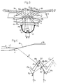
- the marker light shown in figures 1 and 2 comprises (as well as the above mentioned marker light according to WO88/00157) an essentially cylindrical metal casing 1, particularly of an aluminium alloy, having a reflector lamp 2 mounted in its lower part and a transparent cover plate 3 disposed in its upper part and a likewise transparent prism 4 located there-under, for dividing the upwardly directed, collected light bundle from the reflector lamp into two opposite bundle portions (c.f. fig. 3) directed obliquely upwards. From the upper cover plate, oppositely directed light beams are emitted at a desired, particularly small angle to the ground level plane.
- the casing 1 is in this case divided into two parts with an upper, essentially annular cover part 1a and a lower cylindrical part 1b containing the reflector lamp 2 and at its top being provided with an outwardly directed flange portion 1c with an inner seat 5 for the prism 4.
- the cover part 1a of the casing is fixed in a well housing 6, which is indicated with dotted lines, by means of four screws 7, being countersunk in the upper surface of the cover part 1a.
- a cable connection 8 with a contact means 8a for electric supply to the reflector lamp 2 is contained in the lower free space of the well housing, and led through an opening 6a at the side of the well housing 6 to a cable channel (not shown) being disposed in the ground.
- the lower part 1b of the casing is connected to the cover part 1a at the flange portion 1c by means of a number of screws 9, being inserted from below, a ring seal 10 being provided to guarantee the necessary tightness.
- the cover plate is fixed in rotational direction by means of two oppositely disposed somewhat raised tongues 12, projecting a certain distance into the inward recess of the cover part 1a and fitting into a complementarily formed recess 13 in the transparent cover plate 3.
- these tongues 12 serve as wear protectors, particularly against snow clearance by means of steel scraper blades or the like, and also to relieve from vertical loads (deriving from wheels of aeroplanes or vehicles), so that the stresses on the transparent, optically active cover plate 3 are diminished .
- the underlying prism 4 is held in a fixed position between the inward seat 5 of the flange portion 1c and the seal 10 against the lower side of the cover plate 3 at its radially outward side portion.
- the prism is fixed against rotation by means of a number of fixing pins 14, preferably irregularly disposed and fitting into corresponding bores in the prism 4.
- the securing against rotation can of course also be achieved by special shoulders or the like at the seat 5 and corresponding recesses in the prism 4.
- the cover plate 3 is provided with a number of saw-tooth shaped, mutually parallel formations or recesses (four in the shown embodiment), forming in groups mutually parallel, inclined saw-tooth surface portions 16a and 16b, respectively (four of each in the shown embodiment, c.f. fig. 3), and correspondingly the prism 4 is provided with an equally large number of saw-tooth shaped, likewise parallel formations or elevations, forming in groups parallel, inclined saw-tooth surface portions 17a and 17b, respectivly.
- the saw-tooth shaped formations project into each other in a gear-tooth-like manner, however, without contacting each other.
- the angles of inclination are generally different for the surface portions 16a, 16b, on the one hand and the surface portions 17a, 17b, on the other hand.
- the light source i.e. the reflector lamp 2 in the shown embodiment, emits a collected, upwardly directed bundle with mutually parallel, vertically directed light rays L1, L2 , striking the planar lower side 4a of the prism 4 at a right angle, so that the inavoidable losses due to certain reflection becomes minimal.
- the reflection ratio in the lower surface of the prism 4 may be reduced from normally about 4% to considerabely lower values by application of an anti-reflex coating to the lower surface 4a.
- the light rays L1, L2 continue vertically upwards through the prism 4 still in the form of a collected light bundle.
- the light rays L1 (c.f. fig.4), which strike against the inclined surface portions 17b (the right part of the respective saw-tooth formation) are totally reflected at the boundary surface to the air between the lower and the upper saw-tooth formations (at B1 for the ray L1 in fig. 4), so that these light rays L1 are redirected obliquely upwards (to the left in figures 3 and 4) and pass through the upper part of the adjacent inclined surface portion 17a of the same saw-tooth formation (at A1 in fig. 4).
- the light rays L2 are correspondingly totally reflected against said adjacent surface portion 17a (at B2 in fig. 4) and redirected obliquely upwards (to the right in figures 3 and 4), so that they will pass through the respective surface portion 17b (at A2 in fig. 4).
- the thickness of the cover plate 3 is such, that the bundle portions L1' and L2' will be completely separated at the top in the vicinity of the upper side of the cover plate 3, whereby thus an optical dead zone will be formed in the central strip-like portion 3c between the slightly inclined portions 3a, 3b.
- this strip-like portion 3c which extends between the opposite tongues 12 of the cover portion 1a, has a planar configuration. If the cover plate 3 is made thinner (or if the saw-tooth formations occupy a greater area transversely to the edges of the saw-teeth, i.e. an area of extension in the plane of the drawing according to fig.
- the emitted light beams L1'' and L2'' may partially overlap one another, if the upper surface of the cover plate 3 is entirely planar, which is possible if a material with a higher refractive index, and more obtuse saw-tooth formations, are chosen or if the elevational angle ⁇ of the emitted light beams is essentially greater than 3°.
- the emitted light beams L1'' and L2'' could be given a desired colour through arrangement of a colour filter between the light source 2 and the prism 4, for instance in the form of a filter plate 18 (fig. 1) above the reflector lamp 2 or as a surface coating on the planar lower side of the prism 4.
- the geometry (the thickness of the cover plate 3 and the prism 4 and the angles ⁇ , ⁇ , ⁇ , and ⁇ ) as well as the materials (and thus the refractive index) of the cover plate 3 and the prism 4 may be chosen at will by those skilled in the art with proper adjustment of the different parameters.
- a great freedom in the choice of materials and geometry is obtained by making the saw-tooth formations either acute or obtuse and choosing mutually different angles of inclination of the lower saw-tooth formations 16a, 16b of the cover plate 3, on the one hand and the upper saw-tooth formations 17a, 17b of the prism 4 on the other hand.
- cover plate 3 and or the prism 4 one can choose either glass or various types of plastic materials, e.g. epoxy or acrylic plastics or the plastic material, which is marketed under the name MEGITHAN.
Landscapes
- Engineering & Computer Science (AREA)
- Physics & Mathematics (AREA)
- Acoustics & Sound (AREA)
- Mechanical Engineering (AREA)
- Aviation & Aerospace Engineering (AREA)
- Architecture (AREA)
- Civil Engineering (AREA)
- Structural Engineering (AREA)
- Road Signs Or Road Markings (AREA)
- Non-Portable Lighting Devices Or Systems Thereof (AREA)
- Securing Globes, Refractors, Reflectors Or The Like (AREA)
- Optical Elements Other Than Lenses (AREA)
Abstract
Description
- The invention relates to a marker light according to the preamble of
claim 1. - Such marker lights are previously known from WO88/00157 wherein a marker light for airfields, e.g. for runways, taxistrips or the like is described. The marker light according to the invention is, however, generally useful also in other applications, where it is desired to have two oppositely directed light beams being emitted from a light fitting which is flush-mounted in the ground, e.g. in road-ways, particularly as a lane marker, in interchanges, parking areas, storage areas and in other vehicle or pedestrian areas.
- A well known problem with marker lights of this kind, particularly in airfields where relatively great light intensity is necessary in the emitted light beams, is associated with the heat development originating from the light source and the interaction of the light with different optical components in the fitting. Thus, there always has to be a compromise between the luminous efficiency, on the one hand, and the strenght and the functional reliability of the construction materials under working conditions, the working life thereof, etc., on the other hand.
- Against this background, the main object with the present invention is to achieve a marker light making it possible to obtain a high luminous efficiency and a high light intensity in spite of a relatively moderate temperature within the fitting and thus to maintain the strenght and other functional properties as well as the necessary working life of the construction materials.
- Secondary, although equally important objects are to achieve a compact fitting structure, relatively simple and non-expensive manufacture and assembly and low maintenance costs.
- The above main object is achieved for a marker light of the kind defined above in that the prism, being located between the light source and the upper cover plate, has an essentially planar lower surface, being perpendicular to the upwardly directed light bundle from the light source, and an upper surface with at least one saw-tooth formation, the inclined surface portions of which having such angles of inclination that the inciding light will be redirected through total reflection at the respective inclined surface portion and be emitted under the least possible refraction in the respective adjacent, inclined surface portion, while at the same time maintaining said essentially perpendicular angle of incidence onto the lower saw-tooth surface portions of the cover plate and said desired vertical angle for the two light beams being emitted from the upper surface of the cover plate.
- In this connection it should be mentioned that a prism with upwardly directed, inclined surface portions and a lower, horizontal surface is previously known per se from US-A-4 161 770. In the marker light according to this publication, however, the light beams are emitted directly from the upper pointed portion of the prism, which portion therefore protrudes above the slotted cover of the housing, said cover being located essentially in the ground-level plane. Thus, in this case, the marker light does not comprise an approximately planar transparent cover plate, but the pointed edge portion (with large angles of inclination) protrudes through the slot of the cover, which will lead to considerable inconveniences e.g. by snow clearance, wherein the prism could be damaged or displaced from its accurately adjusted position.
- Through appropiate dimensioning of the angles of inclination of the inclined surface portions, taken into account the refractive index of the materials of the cover plate and the prism as well as the desired vertical angle relative to the ground level plane for the emitted light beams, it is possible to optimize the optical arrangements of the marker light been totally reflected at the respective inclined surface portion within the prism, the bundle portions, being directed obliquely upwards in opposite directions will be refracted very little when being emitted from the adjacent inclined surface portions of the prism, as well as when entering into the corresponding saw-tooth portions of the lower side of the cover plate. Here, the rays of the bundle portions form approximately, in practice however not exactly, a right angle to the inclined surface portion in question, whereby the heat development caused by refraction in the internal optic components of the marker light will be very small with associated advantages as to strenght, in particular impact and wear resistance of the upper surface of the cover plate, dimensional stability and functional reliability during operation as well as increased working life. Optimizing the dimensioning of the respective angles of inclination can be carried out by one skilled in the art without too great an effort with the aid of classical optic laws, particularly Snell's refraction law, according to which the refractive index multiplied by sinus for the respective angle of incidence (to the normal) are equal on each side of a boundary surface between two different media.
- Prefarebly, the saw-tooth shaped surface of the prism extends partly into the lower saw-tooth shaped surface of the cover plate, as set forth in
claim 2. Hereby a satisfactory luminous efficiency will be obtained even if the saw-tooth shaped surface portions of the cover plate comprise an angle of inclination that exceeds 45° relative to the ground level plane (i.e. the plane of the cover plate). By letting the saw-tooth shaped surface portions of the prism project into the areas between the saw-tooth shaped surface portions of the cover plate, no shading effect will appear, nor will there be any undesired additional refraction in the adjacent surface portions or any secondary light beam caused thereby and directed in the wrong direction. - The saw-tooth surface of the prism therefore should project so far into the area of the saw-tooth surface of the cover plate that each emitted bundle portion from the respective inclined surface portion of the prism will incide onto the corresponding inclined surface portion of the cover plate and then pass above the adjacent inclined surface portion without interacting with the latter. Such an interaction could bring about the above mentioned undesired additional refraction.
- By arranging the saw-tooth surface portions partly within each other, the total vertical extension of the optical components may be reduced which will result in a compact construction. The construction will be even more compact if the upper cover plate as well as the prism include a number of saw-tooth surface portions, particularly partly projecting into one another, as is stated in
claim 3. Hereby, the total depth of the marker light may be relatively small and the casing of the fitting may be designed for installation into relatively shallow, particularly existing, holes in the ground. - Preferably a cover plate and/or prism is manufactured by hot pressing of a moulded work piece in a tool (c.f. claim 4), whereby subsegment treatment of the optically active surfaces in question will be unnecessary. Hereby, the manufacture will be considerably simplified and costworthy.
- Further features and advantages of the invention will be apparent from the following detailed description of a preferred embodiment, with reference to the appended drawings.
- Fig. 1 shows a marker light according to the invention in a perspective view, a part of the fitting being cut away for increased clarity;
- Fig. 2 shows the marker light from above;
- Fig. 3 shows the optical components schematically with the principal light beams; and
- Fig. 4 shows a part of fig. 3 with light beams in an increased scale.
- The marker light shown in figures 1 and 2 comprises (as well as the above mentioned marker light according to WO88/00157) an essentially
cylindrical metal casing 1, particularly of an aluminium alloy, having areflector lamp 2 mounted in its lower part and atransparent cover plate 3 disposed in its upper part and a likewisetransparent prism 4 located there-under, for dividing the upwardly directed, collected light bundle from the reflector lamp into two opposite bundle portions (c.f. fig. 3) directed obliquely upwards. From the upper cover plate, oppositely directed light beams are emitted at a desired, particularly small angle to the ground level plane. - The
casing 1 is in this case divided into two parts with an upper, essentially annular cover part 1a and a lower cylindrical part 1b containing thereflector lamp 2 and at its top being provided with an outwardly directedflange portion 1c with aninner seat 5 for theprism 4. - The cover part 1a of the casing is fixed in a
well housing 6, which is indicated with dotted lines, by means of four screws 7, being countersunk in the upper surface of the cover part 1a. Acable connection 8 with a contact means 8a for electric supply to thereflector lamp 2 is contained in the lower free space of the well housing, and led through an opening 6a at the side of thewell housing 6 to a cable channel (not shown) being disposed in the ground. - The lower part 1b of the casing is connected to the cover part 1a at the
flange portion 1c by means of a number of screws 9, being inserted from below, aring seal 10 being provided to guarantee the necessary tightness. By the connection of the two parts 1a, 1b of the casing it is at the same time guaranteed that the uppertransparent cover plate 3 and theunderlying prism 4 are being fixed in well defined positions since theupper cover plate 3 fits into an upwardly tapering,conical seat 11, being formed by the side portion of the inward recess of the cover part 1a, and lies with its radially outward, planar lower side against thering seal 10 on top of theflange portion 1c. The cover plate is fixed in rotational direction by means of two oppositely disposed somewhat raisedtongues 12, projecting a certain distance into the inward recess of the cover part 1a and fitting into a complementarily formedrecess 13 in thetransparent cover plate 3. Besides fixing the cover plate against rotation, thesetongues 12 serve as wear protectors, particularly against snow clearance by means of steel scraper blades or the like, and also to relieve from vertical loads (deriving from wheels of aeroplanes or vehicles), so that the stresses on the transparent, opticallyactive cover plate 3 are diminished . - The
underlying prism 4 is held in a fixed position between theinward seat 5 of theflange portion 1c and theseal 10 against the lower side of thecover plate 3 at its radially outward side portion. In the shown embodiment the prism is fixed against rotation by means of a number offixing pins 14, preferably irregularly disposed and fitting into corresponding bores in theprism 4. The securing against rotation can of course also be achieved by special shoulders or the like at theseat 5 and corresponding recesses in theprism 4. - At the lower side of its center portion 15 (c.f. fig. 2) the
cover plate 3 is provided with a number of saw-tooth shaped, mutually parallel formations or recesses (four in the shown embodiment), forming in groups mutually parallel, inclined saw-tooth surface portions prism 4 is provided with an equally large number of saw-tooth shaped, likewise parallel formations or elevations, forming in groups parallel, inclined saw-tooth surface portions surface portions surface portions - The light source, i.e. the
reflector lamp 2 in the shown embodiment, emits a collected, upwardly directed bundle with mutually parallel, vertically directed light rays L₁, L₂ , striking the planar lower side 4a of theprism 4 at a right angle, so that the inavoidable losses due to certain reflection becomes minimal. The reflection ratio in the lower surface of theprism 4 may be reduced from normally about 4% to considerabely lower values by application of an anti-reflex coating to the lower surface 4a. - Thus, the light rays L₁, L₂, continue vertically upwards through the
prism 4 still in the form of a collected light bundle. The light rays L₁ (c.f. fig.4), which strike against theinclined surface portions 17b (the right part of the respective saw-tooth formation) are totally reflected at the boundary surface to the air between the lower and the upper saw-tooth formations (at B₁ for the ray L₁ in fig. 4), so that these light rays L₁ are redirected obliquely upwards (to the left in figures 3 and 4) and pass through the upper part of the adjacentinclined surface portion 17a of the same saw-tooth formation (at A₁ in fig. 4). The light rays L₂ are correspondingly totally reflected against saidadjacent surface portion 17a (at B₂ in fig. 4) and redirected obliquely upwards (to the right in figures 3 and 4), so that they will pass through therespective surface portion 17b (at A₂ in fig. 4). - Provided that
- the
cover plate 3 has a refractive index of 1.4 whereas the prism has a refractive index of 1.5; - the upper
inclined portions cover plate 3 have an angle of inclination δ = 9° to the ground level plane; - the emitted light beams L₁'' and L₂'' form an elevational angle ε = 3° to the ground level plane;
- Thus, the angle of incidence against the slightly inclined (δ = 9°)
upper surface portions cover plate 3, will become 90° - 37° - 9° = 44° to the normal, which will lead to an outgoing angle of 78° to the normal (refractive index 1.4 in the cover plate 3), i.e. the desired elevational angle ε = 90° - 78° - 9° = 3°. - It is obvious from fig. 4 that even the light ray L₂, which incides onto the point B₂ of the
surface portion 17a, i.e. close to the lower edge portion between theadjacent surface portions tooth formation cover plate 3 after refraction at A₂, passage through the intermediate air space and entrance into thecover plate 3 through thesurface portion 16b. Thus, no matter where the total reflection against thesurfaces cover plate 3 without meeting any boundary surfaces, until the respective bundle portion L₁, L₂ reaches the upper, slightlyinclined surfaces - In the shown embodiment the thickness of the
cover plate 3 is such, that the bundle portions L₁' and L₂' will be completely separated at the top in the vicinity of the upper side of thecover plate 3, whereby thus an optical dead zone will be formed in the central strip-like portion 3c between the slightlyinclined portions like portion 3c, which extends between theopposite tongues 12 of the cover portion 1a, has a planar configuration. If thecover plate 3 is made thinner (or if the saw-tooth formations occupy a greater area transversely to the edges of the saw-teeth, i.e. an area of extension in the plane of the drawing according to fig. 3), such a dead zone may be left out, theinclined portions cover plate 3 is entirely planar, which is possible if a material with a higher refractive index, and more obtuse saw-tooth formations, are chosen or if the elevational angle ε of the emitted light beams is essentially greater than 3°. - The emitted light beams L₁'' and L₂'' could be given a desired colour through arrangement of a colour filter between the
light source 2 and theprism 4, for instance in the form of a filter plate 18 (fig. 1) above thereflector lamp 2 or as a surface coating on the planar lower side of theprism 4. - It is obvious that the geometry (the thickness of the
cover plate 3 and theprism 4 and the angles α, β, γ, and δ) as well as the materials (and thus the refractive index) of thecover plate 3 and theprism 4 may be chosen at will by those skilled in the art with proper adjustment of the different parameters. Hereby, a great freedom in the choice of materials and geometry is obtained by making the saw-tooth formations either acute or obtuse and choosing mutually different angles of inclination of the lower saw-tooth formations cover plate 3, on the one hand and the upper saw-tooth formations prism 4 on the other hand. At the same time, however, established norms concerning strenght and resistance at occuring temperatures must be taken into acount. For example, as a material of thecover plate 3 and or theprism 4 one can choose either glass or various types of plastic materials, e.g. epoxy or acrylic plastics or the plastic material, which is marketed under the name MEGITHAN.
Claims (4)
- Marker light comprising a casing (1) to be flush-mounted into the ground, comprising- a lower light source (2) adapted to emit a collected upwardly directed light bundle (L₁,L₂),- a prism (4) placed above the light source with inclined surfaces adapted to divide said upwardly directed light bundle into two bundle portions (L₁',L₂') being directed obliquely upwards in opposite directions, and- an upper cover plate (3), being transparent at least in the area of said bundle portions, with an upper, essentially planar surface (3a,3b), possibly being slightly inclined in two opposite directions and, upon installation of the marker light, lying essentially in the ground level plane, and with a lower surface (16a,16b), being saw-tooth shaped at least in said area,said prism (4) and said saw-tooth shaped surface (16a,16b) being mutually adapted in such a way that said obliquely upwards directed bundle portions will incide essentially perpendicularly onto the respective saw-tooth surface portion (16a,16b) and, after passage through the upper cover plate (3), be refracted in the upper surface (3a,3b) thereof, so that two light beams (L₁'',L₂'') are emitted in opposite directions at a desired vertical angle (ε) to the ground level plane, characterized in that said prism (4) has an essentially planar lower surface (4a) being perpendicular to the upwardly directed light bundle (L₁,L₂) from the light source (2), and an upper surface with at least one saw-tooth formation, the inclined surface portions (17a,17b) of which having such angles of inclination that the inciding light will be redirected through total reflection at the respective inclined surface portion (17a,17b) and be emitted under the least possible refraction in the respective adjacent, inclined surface portion (17a,17b) while at the same time maintaining said essentially perpendicular angle of incidence onto the lower saw-tooth surface portions of the cover plate and said desired vertical angle (ε) for the two light beams (L₁'',L₂'') being emitted from the upper surface of the cover plate.
- Marker light according to claim 1, characterized in that the upper saw-tooth shaped surface (17a,17b) of the prism (4) extends partly into the lower saw-tooth shaped surface (16a,16b) of the cover plate (3).
- Marker light according to claims 1 or 2, characterized in that the upper cover plate (3) as well as the prism (4) are provided with a number of saw-tooth surface portions (16a,16b,17a,17b).
- Marker light according to any one of the previous claims, characterized in that the cover plate (3) and/or the prism (4) are manufactured through hot pressing of a, moulded work piece in a tool.
Applications Claiming Priority (3)
| Application Number | Priority Date | Filing Date | Title |
|---|---|---|---|
| SE9002784A SE465265B (en) | 1990-08-31 | 1990-08-31 | marker lights |
| SE9002784 | 1990-08-31 | ||
| PCT/SE1991/000572 WO1992004232A1 (en) | 1990-08-31 | 1991-08-30 | Marker light |
Publications (2)
| Publication Number | Publication Date |
|---|---|
| EP0544799A1 EP0544799A1 (en) | 1993-06-09 |
| EP0544799B1 true EP0544799B1 (en) | 1995-04-12 |
Family
ID=20380249
Family Applications (1)
| Application Number | Title | Priority Date | Filing Date |
|---|---|---|---|
| EP91916008A Expired - Lifetime EP0544799B1 (en) | 1990-08-31 | 1991-08-30 | Marker light |
Country Status (9)
| Country | Link |
|---|---|
| US (1) | US5335151A (en) |
| EP (1) | EP0544799B1 (en) |
| JP (1) | JP2865864B2 (en) |
| AU (1) | AU8494491A (en) |
| CA (1) | CA2089886A1 (en) |
| DE (1) | DE69108915T2 (en) |
| ES (1) | ES2072012T3 (en) |
| SE (1) | SE465265B (en) |
| WO (1) | WO1992004232A1 (en) |
Cited By (2)
| Publication number | Priority date | Publication date | Assignee | Title |
|---|---|---|---|---|
| DE19615965A1 (en) * | 1996-04-22 | 1997-10-23 | Siemens Ag | Omnidirectional flush-mounted airfield lighting |
| WO1999003729A1 (en) | 1997-07-15 | 1999-01-28 | Siemens Aktiengesellschaft | Inset light |
Families Citing this family (51)
| Publication number | Priority date | Publication date | Assignee | Title |
|---|---|---|---|---|
| US6572240B2 (en) * | 1996-07-26 | 2003-06-03 | Gary L. Reinert, Sr. | Stainless steel airport light cannister apparatus and method |
| US5779349A (en) * | 1993-01-08 | 1998-07-14 | Reinert, Sr.; Gary L. | Adjustable airport runway apparatus and method |
| FR2712564B1 (en) * | 1993-11-17 | 1996-02-09 | Thorn Europhane Sa | Beacon light for aircraft runways or taxiways. |
| US5450300A (en) * | 1994-05-31 | 1995-09-12 | Airport Lighting Systems, Inc. | Lighting device |
| JP2597311B2 (en) * | 1994-06-22 | 1997-04-02 | 日本ライナー株式会社 | Light-emitting road tack |
| DE29505397U1 (en) * | 1995-03-30 | 1995-07-27 | Behnisch, Gerd, Dipl.-Ing., 67227 Frankenthal | Plate lamp for road markings |
| US5556189A (en) * | 1995-04-05 | 1996-09-17 | Hughey & Phillips | Omni-directional airport taxiway light and fixture |
| US5927845A (en) * | 1995-08-28 | 1999-07-27 | Stantech | Integrally formed linear light strip with light emitting diodes |
| US5848837A (en) * | 1995-08-28 | 1998-12-15 | Stantech | Integrally formed linear light strip with light emitting diodes |
| FR2751674B1 (en) * | 1996-07-29 | 1998-09-11 | Mas Philippe | DEVICE FOR FIXING A ROAD EQUIPMENT ELEMENT IN AN ASSOCIATED RECEPTION ELEMENT |
| US5743622A (en) * | 1996-08-14 | 1998-04-28 | Architectural Landscape Lighting | Landscape light with anti-wicking elements and elongated base |
| US5868630A (en) * | 1997-02-06 | 1999-02-09 | Cansak Products Limited | Golf course indicator device |
| US6163247A (en) * | 1997-12-17 | 2000-12-19 | O'meara; James C. | Laser lighting system |
| WO1999031432A1 (en) | 1997-12-17 | 1999-06-24 | Meara James C O | Laser lighting system |
| US6688755B2 (en) | 1997-12-17 | 2004-02-10 | O'meara James C. | Laser lighting system |
| US6007219A (en) * | 1997-12-17 | 1999-12-28 | O'meara; James C. | Laser lighting system |
| EP0940626A1 (en) | 1998-03-02 | 1999-09-08 | Ernst R. Erni | Signal lamp for installation in traffic surfaces |
| DE19809253A1 (en) * | 1998-03-05 | 1999-09-09 | Aqua Signal Ag | Underfloor light and group of underfloor lights |
| US6068384A (en) * | 1998-04-07 | 2000-05-30 | Nsi Enterprises, Inc. | Lighting system |
| US6231206B1 (en) * | 1998-04-15 | 2001-05-15 | Nbbj, Llc | Fiber-optic lighting display |
| US7988316B2 (en) * | 1998-07-10 | 2011-08-02 | Mfpf, Inc. | Stainless steel airport light cannister apparatus and method |
| US6210017B1 (en) * | 1999-05-28 | 2001-04-03 | Minolta Co., Ltd. | Self-emission road device for straight or curved road surface |
| NO318247B1 (en) * | 1999-12-22 | 2005-02-21 | Advanced Light As | Lighting device for installation on a flat surface |
| NO313112B1 (en) * | 1999-12-22 | 2002-08-12 | Advanced Light As | Lighting device for installation on a flat surface |
| JP3818439B2 (en) * | 2000-02-17 | 2006-09-06 | 積水樹脂株式会社 | Road marking device and self-luminous marking system used in the device |
| DE10021725A1 (en) * | 2000-05-04 | 2001-11-15 | Osram Opto Semiconductors Gmbh | Faceted reflector |
| US6612728B2 (en) | 2000-07-07 | 2003-09-02 | Truck-Lite Co., Inc. | Marker lamp with picture frame optics |
| ATE445810T1 (en) * | 2000-08-22 | 2009-10-15 | Koninkl Philips Electronics Nv | LUMINAIRE BASED ON LED LIGHT EMISSION |
| DE50010570D1 (en) * | 2000-10-11 | 2005-07-21 | Swarovski & Co | Marking element for roadways |
| DE10112623A1 (en) * | 2001-03-14 | 2002-10-02 | Siemens Ag | Underfloor fire for traffic areas, e.g. at airports |
| US6969181B1 (en) | 2001-05-08 | 2005-11-29 | Genlyte Thomas Group Llc | Fully recessed unit equipment luminaire |
| US20050122728A1 (en) * | 2002-05-09 | 2005-06-09 | Reinert Gary L.Sr. | Stainless steel airport lighting |
| US7556394B2 (en) * | 2003-01-16 | 2009-07-07 | Anthony Patti | Paver light |
| US7070294B2 (en) * | 2003-01-16 | 2006-07-04 | Anthony Patti | Paver light |
| USD498323S1 (en) | 2003-02-28 | 2004-11-09 | Advanced Light As | Lighting device |
| US7688222B2 (en) | 2003-09-18 | 2010-03-30 | Spot Devices, Inc. | Methods, systems and devices related to road mounted indicators for providing visual indications to approaching traffic |
| US7273301B2 (en) | 2004-05-06 | 2007-09-25 | Genlyte Thomas Group, Llc | Luminaire construction |
| DE102004043194A1 (en) * | 2004-09-03 | 2006-03-09 | Carmen Kotulla | Lighting system for a wall, a ceiling or a floor |
| US7384167B1 (en) | 2005-04-04 | 2008-06-10 | Genlyte Thomas Group, Llc | Optimal wall washing kick reflector |
| US7607794B1 (en) | 2006-08-18 | 2009-10-27 | Genlyte Thomas Group Llc | Recessed wall-wash kick reflector |
| US7722208B1 (en) | 2007-09-30 | 2010-05-25 | Genlyte Thomas Group, Llc | Recessed luminaire trim assembly |
| US7905621B1 (en) | 2008-01-18 | 2011-03-15 | Genlyte Thomas Group, Llc | In-grade lighting fixture |
| US7524078B1 (en) | 2008-01-18 | 2009-04-28 | Genlyte Thomas Group Llc | In-grade lighting fixture |
| US7883234B2 (en) * | 2008-04-18 | 2011-02-08 | Spot Devices, Inc | Embeddable lighting systems |
| DE102010018178A1 (en) * | 2010-04-22 | 2011-10-27 | Hella Kgaa Hueck & Co. | Lighting device for an airport runway |
| US9157210B2 (en) | 2013-03-15 | 2015-10-13 | Anthony Patti | Architectural wall drain assembly |
| US9175840B2 (en) | 2013-03-15 | 2015-11-03 | Evening Star Lighting Inc. | LED wall light fixture |
| US20160281965A1 (en) * | 2015-03-24 | 2016-09-29 | Cooper Technologies Company | Bolt-less Inset Light Fixture & Base |
| CN110873300A (en) * | 2018-08-30 | 2020-03-10 | 中山市叶一照明有限公司 | Right-angle double-sided light-emitting LED wall washer lamp |
| CN113446575B (en) * | 2020-03-25 | 2023-06-27 | 霍尼韦尔国际公司 | Airport runway light |
| US20230324492A1 (en) * | 2022-03-22 | 2023-10-12 | Sheaumann Laser, Inc. | Iris cap for beacon |
Family Cites Families (15)
| Publication number | Priority date | Publication date | Assignee | Title |
|---|---|---|---|---|
| CA805529A (en) * | 1969-02-04 | Brunner Fritz | Recessed marking and projection lamp | |
| CA696555A (en) * | 1964-10-27 | Her Majesty The Queen, In Right Of Canada, As Represented By The Ministe R Of The National Research Council Of Canada | Runway light | |
| US1730325A (en) * | 1922-01-25 | 1929-10-01 | Gen Railway Signal Co | Light signal |
| FR624579A (en) * | 1926-11-15 | 1927-07-21 | Anti-glare device for automobile headlights and other destinations | |
| US2165305A (en) * | 1936-07-24 | 1939-07-11 | Robert J Ruths | Signal device |
| GB537896A (en) * | 1940-01-18 | 1941-07-11 | Frederick Mason | Improvements in or relating to lamps |
| US3007034A (en) * | 1959-09-23 | 1961-10-31 | Oxford Corp | Runway light |
| US3233088A (en) * | 1963-06-27 | 1966-02-01 | Multi Electric Mfg Inc | Lighting apparatus |
| DE1497339C3 (en) * | 1966-09-30 | 1975-10-09 | Siemens Ag, 1000 Berlin Und 8000 Muenchen | Omnidirectional lens body for airfield underfloor lights |
| US3705303A (en) * | 1971-03-12 | 1972-12-05 | Gen Electric | Luminaire |
| CH618654A5 (en) * | 1976-09-17 | 1980-08-15 | Erni & Co Elektro Ind | |
| US4345303A (en) * | 1979-10-02 | 1982-08-17 | Cibie Projecteurs | Optical systems permitting controlled shifting of the beam pattern in headlamps, especially for vehicles |
| US4316241A (en) * | 1979-12-13 | 1982-02-16 | Koehler Manufacturing Company | Method and apparatus for controlling reflected energy including dual light transmitting means for producing a spot to flood configuration |
| GB8505809D0 (en) * | 1985-03-06 | 1985-04-11 | Conway D H | Airport lighting unit |
| SE453425B (en) * | 1986-07-07 | 1988-02-01 | Tetis Plasttetningar Ab | AIRPORT MARKING LIGHT |
-
1990
- 1990-08-31 SE SE9002784A patent/SE465265B/en not_active IP Right Cessation
-
1991
- 1991-08-30 CA CA002089886A patent/CA2089886A1/en not_active Abandoned
- 1991-08-30 US US07/979,878 patent/US5335151A/en not_active Expired - Fee Related
- 1991-08-30 DE DE69108915T patent/DE69108915T2/en not_active Expired - Fee Related
- 1991-08-30 ES ES91916008T patent/ES2072012T3/en not_active Expired - Lifetime
- 1991-08-30 AU AU84944/91A patent/AU8494491A/en not_active Abandoned
- 1991-08-30 EP EP91916008A patent/EP0544799B1/en not_active Expired - Lifetime
- 1991-08-30 JP JP3515029A patent/JP2865864B2/en not_active Expired - Lifetime
- 1991-08-30 WO PCT/SE1991/000572 patent/WO1992004232A1/en not_active Ceased
Cited By (3)
| Publication number | Priority date | Publication date | Assignee | Title |
|---|---|---|---|---|
| DE19615965A1 (en) * | 1996-04-22 | 1997-10-23 | Siemens Ag | Omnidirectional flush-mounted airfield lighting |
| DE19615965C2 (en) * | 1996-04-22 | 1998-09-17 | Siemens Ag | Omnidirectional underfloor fire for airport fields or the like |
| WO1999003729A1 (en) | 1997-07-15 | 1999-01-28 | Siemens Aktiengesellschaft | Inset light |
Also Published As
| Publication number | Publication date |
|---|---|
| JP2865864B2 (en) | 1999-03-08 |
| DE69108915T2 (en) | 1995-08-24 |
| SE9002784D0 (en) | 1990-08-31 |
| US5335151A (en) | 1994-08-02 |
| ES2072012T3 (en) | 1995-07-01 |
| SE465265B (en) | 1991-08-19 |
| JPH06500608A (en) | 1994-01-20 |
| EP0544799A1 (en) | 1993-06-09 |
| AU8494491A (en) | 1992-03-30 |
| DE69108915D1 (en) | 1995-05-18 |
| WO1992004232A1 (en) | 1992-03-19 |
| CA2089886A1 (en) | 1992-03-01 |
Similar Documents
| Publication | Publication Date | Title |
|---|---|---|
| US5335151A (en) | Marker light | |
| US6168294B1 (en) | Airport taxi signal light having LED light array with light processing assembly and dichroic filter | |
| US4231080A (en) | Luminaire with reflecting louvers | |
| US6707435B1 (en) | Optical signaling or display device | |
| US4860182A (en) | Airport lighting | |
| AU589284B2 (en) | An airfield marker light | |
| CA1073423A (en) | Runway light signal assembly | |
| US4621309A (en) | Elongated luminaire | |
| US4731714A (en) | Luminaire | |
| RU2093430C1 (en) | Lighting system for runway and taxying strip and module radiating insert for this system | |
| US4542448A (en) | Lamp assembly | |
| US4910649A (en) | Airfield light having a light source arranged in a house | |
| KR20230021280A (en) | Floor type crosswalk | |
| US4651260A (en) | Roadway luminaire | |
| US4059754A (en) | Louver for light distribution | |
| US4689728A (en) | Lamp assembly | |
| JP3738633B2 (en) | Light irradiation device | |
| KR102435282B1 (en) | Lenses used for road signs | |
| US3398274A (en) | Optically round, mechanically ovate reflector with radially stepped sections | |
| EP1257469B1 (en) | Lighting device for installation in plane surface | |
| CN1069396C (en) | Liminaires | |
| KR100196814B1 (en) | A post for marking road verges | |
| US3188457A (en) | Airport runway luminaire | |
| KR970006280Y1 (en) | Lighting lamp using fresnel lens | |
| CN208670912U (en) | polarized lens |
Legal Events
| Date | Code | Title | Description |
|---|---|---|---|
| PUAI | Public reference made under article 153(3) epc to a published international application that has entered the european phase |
Free format text: ORIGINAL CODE: 0009012 |
|
| 17P | Request for examination filed |
Effective date: 19930211 |
|
| AK | Designated contracting states |
Kind code of ref document: A1 Designated state(s): DE ES FR GB |
|
| 17Q | First examination report despatched |
Effective date: 19940614 |
|
| GRAA | (expected) grant |
Free format text: ORIGINAL CODE: 0009210 |
|
| AK | Designated contracting states |
Kind code of ref document: B1 Designated state(s): DE ES FR GB |
|
| REF | Corresponds to: |
Ref document number: 69108915 Country of ref document: DE Date of ref document: 19950518 |
|
| ET | Fr: translation filed | ||
| REG | Reference to a national code |
Ref country code: ES Ref legal event code: FG2A Ref document number: 2072012 Country of ref document: ES Kind code of ref document: T3 |
|
| PLBI | Opposition filed |
Free format text: ORIGINAL CODE: 0009260 |
|
| PLBF | Reply of patent proprietor to notice(s) of opposition |
Free format text: ORIGINAL CODE: EPIDOS OBSO |
|
| 26 | Opposition filed |
Opponent name: SIEMENS AG ABTLG. ZFE GR PA 1 Effective date: 19960111 |
|
| PLBF | Reply of patent proprietor to notice(s) of opposition |
Free format text: ORIGINAL CODE: EPIDOS OBSO |
|
| PLBO | Opposition rejected |
Free format text: ORIGINAL CODE: EPIDOS REJO |
|
| APAC | Appeal dossier modified |
Free format text: ORIGINAL CODE: EPIDOS NOAPO |
|
| APAE | Appeal reference modified |
Free format text: ORIGINAL CODE: EPIDOS REFNO |
|
| APAC | Appeal dossier modified |
Free format text: ORIGINAL CODE: EPIDOS NOAPO |
|
| PLBN | Opposition rejected |
Free format text: ORIGINAL CODE: 0009273 |
|
| PLAE | Information related to rejection of opposition modified |
Free format text: ORIGINAL CODE: 0009299REJO |
|
| STAA | Information on the status of an ep patent application or granted ep patent |
Free format text: STATUS: OPPOSITION REJECTED |
|
| 27O | Opposition rejected |
Effective date: 19980518 |
|
| R27O | Information related to the rejection of opposition modified: opposition rejected |
Free format text: 980528 |
|
| PGFP | Annual fee paid to national office [announced via postgrant information from national office to epo] |
Ref country code: GB Payment date: 19990728 Year of fee payment: 9 |
|
| PGFP | Annual fee paid to national office [announced via postgrant information from national office to epo] |
Ref country code: FR Payment date: 19990806 Year of fee payment: 9 |
|
| PGFP | Annual fee paid to national office [announced via postgrant information from national office to epo] |
Ref country code: DE Payment date: 19990823 Year of fee payment: 9 |
|
| PGFP | Annual fee paid to national office [announced via postgrant information from national office to epo] |
Ref country code: ES Payment date: 20000131 Year of fee payment: 9 |
|
| PG25 | Lapsed in a contracting state [announced via postgrant information from national office to epo] |
Ref country code: GB Free format text: LAPSE BECAUSE OF NON-PAYMENT OF DUE FEES Effective date: 20000830 |
|
| PG25 | Lapsed in a contracting state [announced via postgrant information from national office to epo] |
Ref country code: ES Free format text: LAPSE BECAUSE OF NON-PAYMENT OF DUE FEES Effective date: 20000831 |
|
| GBPC | Gb: european patent ceased through non-payment of renewal fee |
Effective date: 20000830 |
|
| PG25 | Lapsed in a contracting state [announced via postgrant information from national office to epo] |
Ref country code: FR Free format text: LAPSE BECAUSE OF NON-PAYMENT OF DUE FEES Effective date: 20010430 |
|
| PG25 | Lapsed in a contracting state [announced via postgrant information from national office to epo] |
Ref country code: DE Free format text: LAPSE BECAUSE OF NON-PAYMENT OF DUE FEES Effective date: 20010501 |
|
| REG | Reference to a national code |
Ref country code: FR Ref legal event code: ST |
|
| REG | Reference to a national code |
Ref country code: ES Ref legal event code: FD2A Effective date: 20010911 |
|
| APAH | Appeal reference modified |
Free format text: ORIGINAL CODE: EPIDOSCREFNO |