EP0544253A1 - Damper and method of controlling a door - Google Patents
Damper and method of controlling a door Download PDFInfo
- Publication number
- EP0544253A1 EP0544253A1 EP92120082A EP92120082A EP0544253A1 EP 0544253 A1 EP0544253 A1 EP 0544253A1 EP 92120082 A EP92120082 A EP 92120082A EP 92120082 A EP92120082 A EP 92120082A EP 0544253 A1 EP0544253 A1 EP 0544253A1
- Authority
- EP
- European Patent Office
- Prior art keywords
- cylinder
- housing
- piston
- relative
- door
- Prior art date
- Legal status (The legal status is an assumption and is not a legal conclusion. Google has not performed a legal analysis and makes no representation as to the accuracy of the status listed.)
- Granted
Links
Images


Classifications
-
- E—FIXED CONSTRUCTIONS
- E05—LOCKS; KEYS; WINDOW OR DOOR FITTINGS; SAFES
- E05F—DEVICES FOR MOVING WINGS INTO OPEN OR CLOSED POSITION; CHECKS FOR WINGS; WING FITTINGS NOT OTHERWISE PROVIDED FOR, CONCERNED WITH THE FUNCTIONING OF THE WING
- E05F3/00—Closers or openers with braking devices, e.g. checks; Construction of pneumatic or liquid braking devices
- E05F3/04—Closers or openers with braking devices, e.g. checks; Construction of pneumatic or liquid braking devices with liquid piston brakes
- E05F3/10—Closers or openers with braking devices, e.g. checks; Construction of pneumatic or liquid braking devices with liquid piston brakes with a spring, other than a torsion spring, and a piston, the axes of which are the same or lie in the same direction
- E05F3/104—Closers or openers with braking devices, e.g. checks; Construction of pneumatic or liquid braking devices with liquid piston brakes with a spring, other than a torsion spring, and a piston, the axes of which are the same or lie in the same direction with cam-and-slide transmission between driving shaft and piston within the closer housing
-
- E—FIXED CONSTRUCTIONS
- E05—LOCKS; KEYS; WINDOW OR DOOR FITTINGS; SAFES
- E05F—DEVICES FOR MOVING WINGS INTO OPEN OR CLOSED POSITION; CHECKS FOR WINGS; WING FITTINGS NOT OTHERWISE PROVIDED FOR, CONCERNED WITH THE FUNCTIONING OF THE WING
- E05F3/00—Closers or openers with braking devices, e.g. checks; Construction of pneumatic or liquid braking devices
- E05F3/22—Additional arrangements for closers, e.g. for holding the wing in opened or other position
- E05F3/225—Additional arrangements for closers, e.g. for holding the wing in opened or other position mounted at the bottom of wings, e.g. details related to seals, covers, connections to the wings, embedding in the floor
-
- E—FIXED CONSTRUCTIONS
- E05—LOCKS; KEYS; WINDOW OR DOOR FITTINGS; SAFES
- E05Y—INDEXING SCHEME RELATING TO HINGES OR OTHER SUSPENSION DEVICES FOR DOORS, WINDOWS OR WINGS AND DEVICES FOR MOVING WINGS INTO OPEN OR CLOSED POSITION, CHECKS FOR WINGS AND WING FITTINGS NOT OTHERWISE PROVIDED FOR, CONCERNED WITH THE FUNCTIONING OF THE WING
- E05Y2600/00—Mounting or coupling arrangements for elements provided for in this subclass
- E05Y2600/10—Adjustable or movable
-
- E—FIXED CONSTRUCTIONS
- E05—LOCKS; KEYS; WINDOW OR DOOR FITTINGS; SAFES
- E05Y—INDEXING SCHEME RELATING TO HINGES OR OTHER SUSPENSION DEVICES FOR DOORS, WINDOWS OR WINGS AND DEVICES FOR MOVING WINGS INTO OPEN OR CLOSED POSITION, CHECKS FOR WINGS AND WING FITTINGS NOT OTHERWISE PROVIDED FOR, CONCERNED WITH THE FUNCTIONING OF THE WING
- E05Y2800/00—Details, accessories and auxiliary operations not otherwise provided for
- E05Y2800/20—Combinations of elements
- E05Y2800/21—Combinations of elements of identical elements, e.g. of identical compression springs
-
- E—FIXED CONSTRUCTIONS
- E05—LOCKS; KEYS; WINDOW OR DOOR FITTINGS; SAFES
- E05Y—INDEXING SCHEME RELATING TO HINGES OR OTHER SUSPENSION DEVICES FOR DOORS, WINDOWS OR WINGS AND DEVICES FOR MOVING WINGS INTO OPEN OR CLOSED POSITION, CHECKS FOR WINGS AND WING FITTINGS NOT OTHERWISE PROVIDED FOR, CONCERNED WITH THE FUNCTIONING OF THE WING
- E05Y2800/00—Details, accessories and auxiliary operations not otherwise provided for
- E05Y2800/20—Combinations of elements
- E05Y2800/22—Combinations of elements of not identical elements of the same category, e.g. combinations of not identical springs
-
- E—FIXED CONSTRUCTIONS
- E05—LOCKS; KEYS; WINDOW OR DOOR FITTINGS; SAFES
- E05Y—INDEXING SCHEME RELATING TO HINGES OR OTHER SUSPENSION DEVICES FOR DOORS, WINDOWS OR WINGS AND DEVICES FOR MOVING WINGS INTO OPEN OR CLOSED POSITION, CHECKS FOR WINGS AND WING FITTINGS NOT OTHERWISE PROVIDED FOR, CONCERNED WITH THE FUNCTIONING OF THE WING
- E05Y2900/00—Application of doors, windows, wings or fittings thereof
- E05Y2900/10—Application of doors, windows, wings or fittings thereof for buildings or parts thereof
- E05Y2900/13—Application of doors, windows, wings or fittings thereof for buildings or parts thereof characterised by the type of wing
- E05Y2900/132—Doors
Definitions
- the present invention relates to the use of a damper for controlling the swinging of a pivoted door.
- dampers which are used for controlling the swinging of a door and which comprise a cam and follower mechanism, the cam being connected with the door to turn with the door and the follower being urged by a spring towards the cam so that the spring is compressed when the door is opened and the spring urges the door to swing towards the closed position.
- the damper restricts the speed of closing.
- a door closer For closing and holding closed large and heavy doors, there is a requirement for a door closer having a strong spring. There is also a requirement to restrict the overall dimensions of the door closer. It is possible to provide a strong spring in a housing of acceptable size. However, it is more difficult to provide an adequate damping action in a door closer having a cam and follower mechanism and a strong spring, if the throw of the cam is restricted by the overall dimensions of the door closer. Typically, the throw of the cam of a door closer having acceptable overall dimensions cannot be more than about 20mm. To compensate for the limited throw of the cam, it has been proposed to amplify the movement by means of a lever and apply the amplified movement to the damper. However, this arrangement is not entirely satisfactory. The present invention provides an alternative damper arrangement which is more satisfactory than is the use of a lever.
- a damper comprising a housing, an operating member mounted for movement relative to the housing, a cylinder mounted in the housing for reciprocation relative thereto, a piston movable in the cylinder in a direction parallel to the direction of reciprocation of the cylinder and drive means for transmitting motion between the operating member and the cylinder and transmitting motion between the operating member and the piston to move both the cylinder and the piston relative to the housing and relative to each other when the operating member is moved relative to the housing and is then returned to its initial position.
- the volume of fluid displaced is increased, relative to that which is displaced if only one of the piston and the cylinder is moved and a better damping action can be achieved.
- the preferred damper incorporates a plurality of pistons and relative movement of the cylinder and each piston contributes further to the displacement of fluid and therefore to the damping action.
- the preferred damper comprises first and second guide means adjacent to respective end portions of the cylinder for guiding the cylinder for reciprocation relative to the housing.
- the guide means adjacent to the drive means preferably comprises a pair of outer guide elements incorporated in the housing and a pair of inner guide elements incorporated in the cylinder and lying between the outer guide elements.
- the guide elements of one of these pairs may be rollers.
- the inner guide elements may also guide a piston rod of a first piston, this piston rod extending between the inner guide elements to the drive means.
- the second guide means preferably slides inside the cylinder.
- the damper may further comprise a main spring which drives the cylinder in one direction relative to the housing.
- the cylinder preferably lies inside the main spring. It will be understood that disposing the cylinder inside the main spring facilitates the provision of a relatively short damper, as compared with the overall length which would be required if the cylinder and the main spring are arranged end-to-end.
- the volume of fluid displaced by movement of the cylinder and of a plurality of pistons within the cylinder is sufficient to ensure a good damping action, even when the diameter of the cylinder is sufficiently small for the cylinder to be received in the main spring.
- the outer guide elements may be adjustable relative to the housing in a direction transverse to the direction of reciprocation of the cylinder for adjusting the path along which the cylinder reciprocates and thereby adjusting the position to which the operating member is urged.
- the drive means preferably includes a cam and follower mechanism, the cam being mounted in the housing for turning relative thereto about a cam axis which is transverse to the direction of reciprocation of the piston and the cylinder.
- a pair of transmission elements which occupy respective positions which are fixed with respect to the cylinder or with respect to at least one of the pistons, the transmission elements being spaced apart in a direction transverse to the cam axis and transverse to the direction of reciprocation of the cylinder, and the follower being trapped between the cam and the transmission elements but being free to undergo limited movement relative to those elements.
- the follower is thus able to remain in firm engagement with both of the transmission elements, even if components of the damper are subjected to wear during the service life of the damper.
- a method of controlling the swinging of a pivoted door wherein there is connected with the door a rotary member supported in a housing for turning with the door, upon swinging of the door from a rest position, a piston and a cylinder are moved in opposite directions to draw liquid into the cylinder and, during return of the door to the rest position, the movement of both the piston and the cylinder is reversed, expelling liquid from the cylinder through an orifice.
- the device illustrated in the accompanying drawings comprises a hollow housing 10 in which there is mounted by bearings 59, 60 for turning about an axis 11 a rotary member 12.
- An end portion 13 of the member 12 protrudes at the outside of the housing 10 and receives an arm 14, by means of which the rotary member 12 is connected with a door for turning with the door relative to the housing 10.
- the housing 10 is embedded in a floor and the door is supported for pivoting at the axis 11.
- the arm 14 may be attached to the bottom of the door and is typically received in a recess formed in the door.
- the end portion 13 is non-circular and is received in a complementary opening in the arm at one end thereof.
- a coiled compression spring 15 There is disposed inside the housing 10 a coiled compression spring 15 and a drive mechanism for transmitting motion between the spring and the rotary member 12.
- the drive mechanism is arranged to compress the spring 15 when the door and member 12 are turned from a rest position. The spring then urges the door and member 12 towards the rest position.
- the device illustrated in the drawings is constructed to act as a damper and damp movement of the door towards the rest position under the action of the spring. It will be appreciated that, without the damping action, the door would be accelerated by the spring throughout movement towards the rest position, which would be unacceptably dangerous. In a case where the door is free to swing in either direction from the rest position, damping also enables the door to be brought to rest, when it reaches the rest position, rather than to pass through the rest position and then to oscillate about the rest position.
- a cylinder 16 is mounted inside the housing 10 for reciprocation relative thereto along an axis 17 of the cylinder.
- the axis 17 extends centrally along the length of the housing 10 and either intersects the axis 11 or passes near to that axis.
- the cylinder 16 has at one end an enlarged, hollow head 18, on which there is formed a seat for one end of the spring 15. That part of the cylinder 16 other than the head 18 lies inside the spring 15.
- the spring extends beyond the cylinder 16 to a further seat 19, on which an end of the spring remote from the head 18 bears.
- the cylinder is open at both of its ends.
- the seat 19 is mounted on a carrier 20 which is supported in one end portion of the housing 10 against movement outwards of the housing.
- the carrier 20 can turn relative to the housing about the axis 17 and a non-circular end portion 21 of the carrier protrudes from the end of the housing to facilitate turning of the carrier by means of a suitable tool.
- the seat 19 is annular and has a female screw thread cooperating with a male screw thread on the carrier 20.
- the seat 19 is restrained against turning relative to the housing by the spring 15. This may be achieved by friction between the spring and the seat. Additionally, there may be formed on the seat 19 an axially projecting lug which cooperates with the spring to prevent turning of the seat relative to the spring. Accordingly, by turning of the carrier 20 relative to the housing 10, the seat 19 can be screwed along the housing to increase or decrease the stress in the spring 15.
- the carrier 20 is integral with a hollow piston 22 over which the cylinder 16 slides.
- the piston has an annular seal for bearing on the wall of the cylinder to establish an oil-tight relation between the piston and the cylinder.
- the piston 22 serves to guide the adjacent end portion of the cylinder 16 for movement relative to the housing along the axis 17.
- the further guide means is represented in Figure 3 and comprises a pair of outer guide elements 23 and 24 incorporated in the housing 10 and a pair of inner guide elements 25 and 26 incorporated in the head 18 of the cylinder.
- the inner guide elements are formed as rollers and are mounted for free rotation relative to the head 18 about respective axes 27 and 28 which lie on opposite sides of the axis 17, are equally spaced from that axis and are perpendicular to that axis.
- the roller axes 27 and 28 are parallel to the axis 11.
- the outer guide elements 23 and 24 have respective flat, mutually parallel faces on which the rollers 25 and 26 run.
- a first cam 29 lies inside the housing 10, adjacent to the cylinder head 18, and is fixed with respect to the rotary operating member 12.
- the cylinder 16 is provided with a cam follower for cooperating with the cam 29.
- the cam follower is a roller 30 which engages the periphery of the cam 29.
- a pair of rollers 31 and 32 mounted for free rotation relative to the head 18 about the axes 27 and 28.
- the roller 30 is, however, free to undergo limited movement relative to the cylinder, although the roller 30 is trapped in the head 18.
- the cylinder 16 is urged towards the axis 11 by the main spring 15. Accordingly, the rollers 31 and 32 are held in firm engagement with the cam follower roller 30 and the latter roller is held in firm engagement with the first cam 29. This relationship is achieved, irrespective of manufacturing tolerances and irrespective of normal wear of components which may occur during the service life of the device.
- a second cam 33 which is identical with the cam 29, is mounted in fixed relation to, but spaced along the axis 11 from, the first cam 29.
- the cylinder head 18 is provided with a further pair of rollers corresponding to the rollers 31 and 32 and mounted for rotation relative to the head about the axes 27 and 28 and with a further floating roller 36 corresponding to the floating roller 30, the roller 36 cooperating with the second cam and with the further pair of rollers in the same manner as that in which the floating roller 30 cooperates with the first cam and with the rollers 31 and 32.
- a movable piston 37 is mounted inside the cylinder 16 for reciprocation relative thereto.
- the piston 37 comprises a head 38 bearing a peripheral seal which cooperates with the wall of the cylinder and a piston rod 39 extending from the head 38 in a direction towards the axis 11.
- the piston rod 39 passes between the guide rollers 25 and 26 and is thereby guided for movement along the axis 17.
- the piston rod 39 carries a cam follower in the form of a roller 40.
- the roller 40 bears on the periphery of a cam 41 interposed between the cams 29 and 33 and fixed with respect thereto.
- a third piston 43 is also mounted in the cylinder 16 for reciprocation relative thereto.
- the third piston comprises a head 44 bearing a peripheral seal which cooperates with the wall of the cylinder and a piston rod 45 which extends from the head 44 in a direction towards the piston 37 and the axis 11.
- a coiled compression spring 46 which lies mainly inside the hollow piston 22 and which protrudes therefrom to the head 44 of the piston 43 urges the piston 43 towards the piston 37 and thereby urges the piston 37 towards the axis 11. This maintains the roller 40 in engagement with the periphery of the cam 41.
- the cylinder 16 contains an annular plug 47 which lies between the piston head 38 and the piston head 44.
- This plug is fixed with respect to the cylinder and is sealed to the cylinder.
- the cylinder may be formed in two parts, which meet at the plug 47.
- the plug may be employed to connect these parts of the cylinder together.
- the piston rod 45 extends through the plug 47 and is sealed with respect thereto by an annular seal mounted in the plug.
- the plug divides a first chamber 48 in the cylinder 16, lying between the piston head 38 and the plug, from a second chamber 49 lying between the plug and the piston head 44.
- a third chamber 50 inside the cylinder extends from the piston head 44 to the fixed piston 22 and includes the interior of that piston. Passages are provided for the flow of oil between these chambers and the space 51 outside the cylinder 16 which contains the main spring 15.
- a passage providing communication between the third chamber 50 and the space 51 contains an adjustable needle valve 52.
- the needle valve is screwed into a threaded bore formed in the carrier 20 and a portion of the valve protrudes at the outside of the carrier 20, so that a tool can be applied to the needle valve to adjust the degree of constriction of the flow path past the needle valve.
- the needle valve extends into an annular restrictor disposed in the central bore of the carrier 20. Lateral ports extend from this central bore to the space 51 at a position between the restrictor and the adjacent end of the housing 10.
- a port 53 is formed in the cylinder 16 at a position between the plug 47 and the piston head 44. This port provides for relatively free flow of oil between the space 51 and the second chamber 49.
- a filter may be provided in the port 53 to prevent solid matter entering the cylinder.
- Communication between the second chamber 49 and the third chamber 50 is provided by a passage 54 formed in the piston head 44. This passage contains a non-return valve which permits flow in a direction from the second chamber to the third chamber but prevents flow through the passage 54 from the third chamber to the second chamber.
- the third chamber 50 is in communication with the first chamber 48 via passages formed in the piston head 44 and the piston rod 45, which is hollow along its entire length.
- a recess is formed in that face of the piston head 38 which abuts the piston rod 45, to ensure free flow between the interior of the piston rod 45 and the first chamber 48.
- the housing 10 including the interior of the cylinder 16 and all other hollow components, is charged with oil.
- Figure 2 illustrates the positions of the first cam 29, cylinder 16 and the pistons 22, 37 and 43, when the rotary operating member 12 is in a rest position relative to the housing 10. This is the position occupied when the main spring 15 is extended. It corresponds to the closed position of a door connected with the operating member 12.
- Figure 3 illustrates the positions of the cam 41, guide rollers 25 and 26, the cylinder and the pistons also when the operating member 12 is in the rest position.
- the cam 29 drives the floating roller 30 away from the axis 11, a small, initial, angular movement of the cam causing a relatively large displacement of the roller.
- the spring 46 causes the pistons 37 and 43 to move with the roller 40 so that the pistons move relative to the housing 10 in a direction opposite to that in which the cylinder 16 moves relative to the housing. Accordingly, the piston head 38 moves away from the plug 47 through a distance equal to the combined strokes of the cylinder and the pistons.
- the first chamber 48 is therefore enlarged considerably.
- the volume of the third chamber 50 also is increased, although by a smaller amount, as the piston 43 moves away from the fixed piston 22. As the volumes of the chambers are increased, oil flows from the space 51 through the port 53 and the passage 54 to the third chamber and from there through the hollow piston rod 45 to the first chamber.
- the cam 41 As the cam 41 is turned towards the rest position, it drives the roller 40 away from the axis 11.
- the piston head 38 is moved towards the plug 47 so that the volume of the first chamber 48 is reduced. Oil is expelled from that chamber along the interior of the hollow piston rod 45 to the third chamber 50.
- the piston 43 also is moved away from the axis 11 towards the fixed piston 22 so that the volume of the third chamber 50 also is reduced. Flow of oil from the third chamber to the second chamber 49 is prevented by the non-return valve in the passage 54. Accordingly, all of the oil expelled from the first chamber 48 and from the third chamber 50 must flow through the orifice restricted by the needle valve 52. Closing movement of the door is thereby controlled.
- the shape of the cam 29 is selected to provide that the action of the floating roller 30 on the cam, when the operating member 12 is in the rest position, is a strong centring action, driving the cam to and holding the cam in the rest position.
- the orientation of the cam relative to the housing 10, when in the rest position, can be adjusted through a small range by adjusting the outer guide elements 23 and 24 in a direction transverse to the axis 11.
- the cams 29 and 33 can be turned from the rest position in either direction beyond 90° towards 180°.
- the external dimensions of the housing 10 can be sufficiently small for the housing to be incorporated in a transom above a door. In some cases, the size of the housing, relative to that of the door, may be such that the housing can be incorporated in the door.
- Each of the outer guide elements 23 and 24 is formed with a male screw thread and is screwed into a threaded opening in the housing 10.
- the guide elements are screwed towards each other until they are in firm engagement with respective ones of the guide rollers 25 and 26.
- the outer guide elements may be set in positions such that the axis 17 intersects the axis 11.
- both guide elements may be moved in the same direction relative to the housing to shift the axis 17 to one side of the axis 11 and thereby adjust the rest position of the operating member 12.
- each of the outer guide elements may be adapted to receive a tool.
- a slot may be formed in the face of the guide element which is exposed at the outside of the housing 10.
- transmission means for transmitting rotary drive to both of the outer drive elements concurrently.
- the transmission means includes a sprocket 56 mounted in the body adjacent to the guide element 23 and having teeth meshing with teeth formed at the periphery of the guide element.
- a corresponding sprocket 57 is mounted in the body adjacent to the guide element 24.
- Each of the sprockets includes a hub in which there are formed a number of radial bores for receiving a bar or other tool, by means of which the sprocket can be turned relative to the housing. There is in the housing an opening which permits access to a part of the hub of each sprocket.
- the sprockets 56 and 57 have a common axis and are connected together by a shaft 58 which extends across the housing 10.
- the sprockets are fixed on opposite end portions of the shaft 58 so that the sprockets are constrained to turn with the shaft.
- the shaft 58 is maintained under torsional stress. This stress tends to turn the outer guide elements 23 and 24 in respective directions corresponding to screwing of the guide elements towards each other. Accordingly, the guide elements exert pressure on the guide rollers 25 and 26. The reaction to this pressure resists the turning moment exerted on the sprockets 56 and 57 by the shaft 58. The guide rollers 25 and 26 maintain between the outer guide elements 23 and 24 a separation which is greater than the separation between the guide elements when the shaft 58 is unstressed.
Abstract
Description
- From one aspect, the present invention relates to the use of a damper for controlling the swinging of a pivoted door. There are known dampers which are used for controlling the swinging of a door and which comprise a cam and follower mechanism, the cam being connected with the door to turn with the door and the follower being urged by a spring towards the cam so that the spring is compressed when the door is opened and the spring urges the door to swing towards the closed position. The damper restricts the speed of closing.
- For closing and holding closed large and heavy doors, there is a requirement for a door closer having a strong spring. There is also a requirement to restrict the overall dimensions of the door closer. It is possible to provide a strong spring in a housing of acceptable size. However, it is more difficult to provide an adequate damping action in a door closer having a cam and follower mechanism and a strong spring, if the throw of the cam is restricted by the overall dimensions of the door closer. Typically, the throw of the cam of a door closer having acceptable overall dimensions cannot be more than about 20mm. To compensate for the limited throw of the cam, it has been proposed to amplify the movement by means of a lever and apply the amplified movement to the damper. However, this arrangement is not entirely satisfactory. The present invention provides an alternative damper arrangement which is more satisfactory than is the use of a lever.
- According to a first aspect of the invention, there is provided a damper comprising a housing, an operating member mounted for movement relative to the housing, a cylinder mounted in the housing for reciprocation relative thereto, a piston movable in the cylinder in a direction parallel to the direction of reciprocation of the cylinder and drive means for transmitting motion between the operating member and the cylinder and transmitting motion between the operating member and the piston to move both the cylinder and the piston relative to the housing and relative to each other when the operating member is moved relative to the housing and is then returned to its initial position.
- By moving both the cylinder and the piston, the volume of fluid displaced is increased, relative to that which is displaced if only one of the piston and the cylinder is moved and a better damping action can be achieved.
- The preferred damper incorporates a plurality of pistons and relative movement of the cylinder and each piston contributes further to the displacement of fluid and therefore to the damping action. The preferred damper comprises first and second guide means adjacent to respective end portions of the cylinder for guiding the cylinder for reciprocation relative to the housing. The guide means adjacent to the drive means preferably comprises a pair of outer guide elements incorporated in the housing and a pair of inner guide elements incorporated in the cylinder and lying between the outer guide elements. The guide elements of one of these pairs may be rollers.
- The inner guide elements may also guide a piston rod of a first piston, this piston rod extending between the inner guide elements to the drive means.
- The second guide means preferably slides inside the cylinder.
- The damper may further comprise a main spring which drives the cylinder in one direction relative to the housing. The cylinder preferably lies inside the main spring. It will be understood that disposing the cylinder inside the main spring facilitates the provision of a relatively short damper, as compared with the overall length which would be required if the cylinder and the main spring are arranged end-to-end. In the preferred damper, the volume of fluid displaced by movement of the cylinder and of a plurality of pistons within the cylinder is sufficient to ensure a good damping action, even when the diameter of the cylinder is sufficiently small for the cylinder to be received in the main spring.
- The outer guide elements may be adjustable relative to the housing in a direction transverse to the direction of reciprocation of the cylinder for adjusting the path along which the cylinder reciprocates and thereby adjusting the position to which the operating member is urged.
- The drive means preferably includes a cam and follower mechanism, the cam being mounted in the housing for turning relative thereto about a cam axis which is transverse to the direction of reciprocation of the piston and the cylinder.
- In the preferred damper, there is provided a pair of transmission elements which occupy respective positions which are fixed with respect to the cylinder or with respect to at least one of the pistons, the transmission elements being spaced apart in a direction transverse to the cam axis and transverse to the direction of reciprocation of the cylinder, and the follower being trapped between the cam and the transmission elements but being free to undergo limited movement relative to those elements. The follower is thus able to remain in firm engagement with both of the transmission elements, even if components of the damper are subjected to wear during the service life of the damper.
- It is a common problem with known dampers used for controlling the swinging of a pivoted door that variations in the dimensions of components within accepted tolerance limits and wear of components during the service life of a damper give rise to situations in which the door can be turned through a few degrees without compression of a spring incorporated in the damper taking place. Such movement is not opposed by the damper. The door is free to move through a small angle and the damper does not set the door in a predetermined position with sufficient accuracy. This is a particular problem in a case where the door is required to constitute a fire barrier.
- According to a second aspect of the invention, there is provided a method of controlling the swinging of a pivoted door wherein there is connected with the door a rotary member supported in a housing for turning with the door, upon swinging of the door from a rest position, a piston and a cylinder are moved in opposite directions to draw liquid into the cylinder and, during return of the door to the rest position, the movement of both the piston and the cylinder is reversed, expelling liquid from the cylinder through an orifice.
- An example of a door closer incorporating a damper according to the invention will now be described, with reference to the accompanying drawings, wherein:
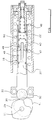
- FIGURE 1 shows a cross section through the door closer in a vertical plane and with an operating member of the door closer in a rest position;
- FIGURE 2 is a diagrammatic representation of a cross section through the door closer along the stepped line II-II indicated in Figure 1,
- FIGURE 3 is a representation similar to that of Figure 2 of a cross section on the line III-III of Figure 1,
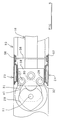
- FIGURE 4 is a diagram similar to Figure 2 but illustrating parts of the door closer in positions occupied when the operating member is out of the rest position;
- FIGURE 5 illustrates diagrammatically certain parts of the door closer, as viewed in cross section in the plane V-V of Figure 1.
- The device illustrated in the accompanying drawings comprises a
hollow housing 10 in which there is mounted bybearings rotary member 12. Anend portion 13 of themember 12 protrudes at the outside of thehousing 10 and receives anarm 14, by means of which therotary member 12 is connected with a door for turning with the door relative to thehousing 10. Typically, thehousing 10 is embedded in a floor and the door is supported for pivoting at theaxis 11. Thearm 14 may be attached to the bottom of the door and is typically received in a recess formed in the door. Theend portion 13 is non-circular and is received in a complementary opening in the arm at one end thereof. - There is disposed inside the housing 10 a coiled
compression spring 15 and a drive mechanism for transmitting motion between the spring and therotary member 12. The drive mechanism is arranged to compress thespring 15 when the door andmember 12 are turned from a rest position. The spring then urges the door andmember 12 towards the rest position. - The device illustrated in the drawings is constructed to act as a damper and damp movement of the door towards the rest position under the action of the spring. It will be appreciated that, without the damping action, the door would be accelerated by the spring throughout movement towards the rest position, which would be unacceptably dangerous. In a case where the door is free to swing in either direction from the rest position, damping also enables the door to be brought to rest, when it reaches the rest position, rather than to pass through the rest position and then to oscillate about the rest position.
- A
cylinder 16 is mounted inside thehousing 10 for reciprocation relative thereto along anaxis 17 of the cylinder. Theaxis 17 extends centrally along the length of thehousing 10 and either intersects theaxis 11 or passes near to that axis. Thecylinder 16 has at one end an enlarged,hollow head 18, on which there is formed a seat for one end of thespring 15. That part of thecylinder 16 other than thehead 18 lies inside thespring 15. The spring extends beyond thecylinder 16 to afurther seat 19, on which an end of the spring remote from thehead 18 bears. The cylinder is open at both of its ends. - The
seat 19 is mounted on acarrier 20 which is supported in one end portion of thehousing 10 against movement outwards of the housing. Thecarrier 20 can turn relative to the housing about theaxis 17 and anon-circular end portion 21 of the carrier protrudes from the end of the housing to facilitate turning of the carrier by means of a suitable tool. Theseat 19 is annular and has a female screw thread cooperating with a male screw thread on thecarrier 20. Theseat 19 is restrained against turning relative to the housing by thespring 15. This may be achieved by friction between the spring and the seat. Additionally, there may be formed on theseat 19 an axially projecting lug which cooperates with the spring to prevent turning of the seat relative to the spring. Accordingly, by turning of thecarrier 20 relative to thehousing 10, theseat 19 can be screwed along the housing to increase or decrease the stress in thespring 15. - The
carrier 20 is integral with ahollow piston 22 over which thecylinder 16 slides. The piston has an annular seal for bearing on the wall of the cylinder to establish an oil-tight relation between the piston and the cylinder. Thepiston 22 serves to guide the adjacent end portion of thecylinder 16 for movement relative to the housing along theaxis 17. - Further guide means is provided for guiding the
head 18 for movement along theaxis 17 relative to thehousing 10. The further guide means is represented in Figure 3 and comprises a pair ofouter guide elements housing 10 and a pair ofinner guide elements head 18 of the cylinder. The inner guide elements are formed as rollers and are mounted for free rotation relative to thehead 18 aboutrespective axes axis 17, are equally spaced from that axis and are perpendicular to that axis. The roller axes 27 and 28 are parallel to theaxis 11. Theouter guide elements rollers - A
first cam 29 lies inside thehousing 10, adjacent to thecylinder head 18, and is fixed with respect to therotary operating member 12. Thecylinder 16 is provided with a cam follower for cooperating with thecam 29. In the example illustrated, the cam follower is aroller 30 which engages the periphery of thecam 29. For transmitting force between thehead 18 of the cylinder and theroller 30, there is provided a pair ofrollers head 18 about theaxes rollers cylinder 16. Theroller 30 is, however, free to undergo limited movement relative to the cylinder, although theroller 30 is trapped in thehead 18. - The
cylinder 16 is urged towards theaxis 11 by themain spring 15. Accordingly, therollers cam follower roller 30 and the latter roller is held in firm engagement with thefirst cam 29. This relationship is achieved, irrespective of manufacturing tolerances and irrespective of normal wear of components which may occur during the service life of the device. - A
second cam 33, which is identical with thecam 29, is mounted in fixed relation to, but spaced along theaxis 11 from, thefirst cam 29. Thecylinder head 18 is provided with a further pair of rollers corresponding to therollers axes roller 36 corresponding to the floatingroller 30, theroller 36 cooperating with the second cam and with the further pair of rollers in the same manner as that in which the floatingroller 30 cooperates with the first cam and with therollers - A
movable piston 37 is mounted inside thecylinder 16 for reciprocation relative thereto. Thepiston 37 comprises ahead 38 bearing a peripheral seal which cooperates with the wall of the cylinder and apiston rod 39 extending from thehead 38 in a direction towards theaxis 11. Thepiston rod 39 passes between theguide rollers axis 17. At its end remote from thehead 38, thepiston rod 39 carries a cam follower in the form of aroller 40. Theroller 40 bears on the periphery of acam 41 interposed between thecams - A
third piston 43 is also mounted in thecylinder 16 for reciprocation relative thereto. The third piston comprises ahead 44 bearing a peripheral seal which cooperates with the wall of the cylinder and apiston rod 45 which extends from thehead 44 in a direction towards thepiston 37 and theaxis 11. A coiledcompression spring 46, which lies mainly inside thehollow piston 22 and which protrudes therefrom to thehead 44 of thepiston 43 urges thepiston 43 towards thepiston 37 and thereby urges thepiston 37 towards theaxis 11. This maintains theroller 40 in engagement with the periphery of thecam 41. - The
cylinder 16 contains anannular plug 47 which lies between thepiston head 38 and thepiston head 44. This plug is fixed with respect to the cylinder and is sealed to the cylinder. For convenience of manufacture and assembly of components of the device, the cylinder may be formed in two parts, which meet at theplug 47. The plug may be employed to connect these parts of the cylinder together. Thepiston rod 45 extends through theplug 47 and is sealed with respect thereto by an annular seal mounted in the plug. The plug divides afirst chamber 48 in thecylinder 16, lying between thepiston head 38 and the plug, from asecond chamber 49 lying between the plug and thepiston head 44. Athird chamber 50 inside the cylinder extends from thepiston head 44 to the fixedpiston 22 and includes the interior of that piston. Passages are provided for the flow of oil between these chambers and thespace 51 outside thecylinder 16 which contains themain spring 15. - A passage providing communication between the
third chamber 50 and thespace 51 contains anadjustable needle valve 52. The needle valve is screwed into a threaded bore formed in thecarrier 20 and a portion of the valve protrudes at the outside of thecarrier 20, so that a tool can be applied to the needle valve to adjust the degree of constriction of the flow path past the needle valve. The needle valve extends into an annular restrictor disposed in the central bore of thecarrier 20. Lateral ports extend from this central bore to thespace 51 at a position between the restrictor and the adjacent end of thehousing 10. - A
port 53 is formed in thecylinder 16 at a position between theplug 47 and thepiston head 44. This port provides for relatively free flow of oil between thespace 51 and thesecond chamber 49. A filter may be provided in theport 53 to prevent solid matter entering the cylinder. Communication between thesecond chamber 49 and thethird chamber 50 is provided by apassage 54 formed in thepiston head 44. This passage contains a non-return valve which permits flow in a direction from the second chamber to the third chamber but prevents flow through thepassage 54 from the third chamber to the second chamber. - The
third chamber 50 is in communication with thefirst chamber 48 via passages formed in thepiston head 44 and thepiston rod 45, which is hollow along its entire length. A recess is formed in that face of thepiston head 38 which abuts thepiston rod 45, to ensure free flow between the interior of thepiston rod 45 and thefirst chamber 48. - During manufacture of the device, the
housing 10, including the interior of thecylinder 16 and all other hollow components, is charged with oil. - Figure 2 illustrates the positions of the
first cam 29,cylinder 16 and thepistons rotary operating member 12 is in a rest position relative to thehousing 10. This is the position occupied when themain spring 15 is extended. It corresponds to the closed position of a door connected with the operatingmember 12. Figure 3 illustrates the positions of thecam 41, guiderollers member 12 is in the rest position. When the operating member is turned from the rest position, thecam 29 drives the floatingroller 30 away from theaxis 11, a small, initial, angular movement of the cam causing a relatively large displacement of the roller. Since therollers roller 30 and have respective axes which are fixed with respect to thecylinder 16, the cylinder is caused to move away from theaxis 11 with the floatingroller 30. The positions occupied when the cam has been turned through an angle of 60° from the rest position are illustrated in Figure 4. It will be noted that turning of the cam from the rest position causes thecylinder 16 to slide along the fixedpiston 22. Figure 4 also shows the positions of theroller 40 and thepiston 37 when thecam 41 has turned 60° from the rest position. It will be seen that this movement of the cam permits theroller 40 to approach theaxis 11. Thespring 46 causes thepistons roller 40 so that the pistons move relative to thehousing 10 in a direction opposite to that in which thecylinder 16 moves relative to the housing. Accordingly, thepiston head 38 moves away from theplug 47 through a distance equal to the combined strokes of the cylinder and the pistons. Thefirst chamber 48 is therefore enlarged considerably. The volume of thethird chamber 50 also is increased, although by a smaller amount, as thepiston 43 moves away from the fixedpiston 22. As the volumes of the chambers are increased, oil flows from thespace 51 through theport 53 and thepassage 54 to the third chamber and from there through thehollow piston rod 45 to the first chamber. - Turning of the
cam 29 from the rest position moves thecylinder 16 in a direction to compress themain spring 15. When the associated door is released, thespring 15 drives thecylinder 16 towards theaxis 11. The cam and follower mechanism transmits motion from thecylinder 16 to the operatingmember 12 so that the door is swung towards the rest position. Turning of the operating member towards the rest position is yieldably opposed by the damping action of the device. - As the
cam 41 is turned towards the rest position, it drives theroller 40 away from theaxis 11. Thepiston head 38 is moved towards theplug 47 so that the volume of thefirst chamber 48 is reduced. Oil is expelled from that chamber along the interior of thehollow piston rod 45 to thethird chamber 50. Thepiston 43 also is moved away from theaxis 11 towards the fixedpiston 22 so that the volume of thethird chamber 50 also is reduced. Flow of oil from the third chamber to thesecond chamber 49 is prevented by the non-return valve in thepassage 54. Accordingly, all of the oil expelled from thefirst chamber 48 and from thethird chamber 50 must flow through the orifice restricted by theneedle valve 52. Closing movement of the door is thereby controlled. - The shape of the
cam 29 is selected to provide that the action of the floatingroller 30 on the cam, when the operatingmember 12 is in the rest position, is a strong centring action, driving the cam to and holding the cam in the rest position. The orientation of the cam relative to thehousing 10, when in the rest position, can be adjusted through a small range by adjusting theouter guide elements axis 11. - The
cams housing 10 can be sufficiently small for the housing to be incorporated in a transom above a door. In some cases, the size of the housing, relative to that of the door, may be such that the housing can be incorporated in the door. - Each of the
outer guide elements housing 10. The guide elements are screwed towards each other until they are in firm engagement with respective ones of theguide rollers axis 17 intersects theaxis 11. Alternatively, both guide elements may be moved in the same direction relative to the housing to shift theaxis 17 to one side of theaxis 11 and thereby adjust the rest position of the operatingmember 12. To facilitate adjustment, each of the outer guide elements may be adapted to receive a tool. For example, a slot may be formed in the face of the guide element which is exposed at the outside of thehousing 10. However, in the example illustrated in the drawings, transmission means is provided for transmitting rotary drive to both of the outer drive elements concurrently. The transmission means includes asprocket 56 mounted in the body adjacent to theguide element 23 and having teeth meshing with teeth formed at the periphery of the guide element. A correspondingsprocket 57 is mounted in the body adjacent to theguide element 24. Each of the sprockets includes a hub in which there are formed a number of radial bores for receiving a bar or other tool, by means of which the sprocket can be turned relative to the housing. There is in the housing an opening which permits access to a part of the hub of each sprocket. Thesprockets shaft 58 which extends across thehousing 10. The sprockets are fixed on opposite end portions of theshaft 58 so that the sprockets are constrained to turn with the shaft. - The
shaft 58 is maintained under torsional stress. This stress tends to turn theouter guide elements guide rollers sprockets shaft 58. Theguide rollers outer guide elements 23 and 24 a separation which is greater than the separation between the guide elements when theshaft 58 is unstressed. - With the particular arrangement illustrated in the accompanying drawings, operation of the damper to compress the main spring is accompanied by the drawing of fluid into the cylinder. When the spring subsequently extends, fluid is expelled from the cylinder at a restricted rate so that the rate of extension of the spring is controlled. It will be appreciated that the arrangement illustrated may readily be modified to provide that, upon compression of the main spring, fluid is drawn into the space outside the cylinder and when the spring subsequently extends fluid is expelled from that space through an orifice to the interior of the cylinder, the rate of flow being restricted to control the rate of extension of the spring.
- The features disclosed in the foregoing description, or the following claims, or the accompanying drawings, expressed in their specific forms or in terms of a means for performing the disclosed function, or a method or process for attaining the disclosed result, as appropriate may, separately or in any combination of such features, be utilised for realising the invention in diverse forms thereof.
Claims (13)
- A damper comprising a housing (10), an operating member (12) mounted for movement relative to the housing, a cylinder (16) mounted in the housing for reciprocation relative thereto, a piston (37) movable in the cylinder in a direction parallel to the direction of reciprocation of the cylinder and drive means (29, 30, 33, 36, 40, 41) for transmitting motion between the operating member and the cylinder and transmitting motion between the operating member and the piston to move both the cylinder and the piston relative to the housing and relative to each other when the operating member is moved relative to the housing and is returned to its initial position.
- A damper according to Claim 1 further comprising a second piston (22) which remains stationary relative to the housing (10) during movement of the operating member (12) relative to the housing.
- A damper according to Claim 2 wherein both pistons (22, 37) slide inside the same cylinder (16).
- A damper according to Claim 2 or Claim 3 further comprising a third piston (43) which moves with the first piston (37) relative to the housing (10).
- A damper according to any preceding claim comprising first and second guide means adjacent to respective end portions of the cylinder for guiding the cylinder for reciprocation relative to the housing, wherein the first guide means is adjacent to the drive means and comprises a pair of outer guide elements (23, 24) incorporated in the housing and a pair of inner guide elements (25, 26) incorporated in the cylinder and lying between the outer guide elements.
- A damper according to Claim 5 wherein the outer guide elements (23, 24) are adjustable relative to the housing.
- A damper according to Claim 5 or Claim 6 wherein the first piston (37) has a piston rod (39) which extends between the inner guide elements (25, 26) to the drive means and the inner guide elements guide the piston rod for reciprocation relative to the cylinder (16).
- A damper according to any preceding claim further comprising a main spring (15) which drives the cylinder (16) in one direction relative to the housing and wherein the cylinder lies inside the main spring.
- A damper according to Claim 8 further comprising a pair of transmission elements (31, 32) which occupy respective positions which are fixed with respect to the cylinder, wherein the drive means includes a cam (29) and a follower (30), wherein the cam is fixed with respect to the operating member (12), the follower is trapped between the transmission elements and the cam and wherein the transmission elements are spaced apart in a direction transverse to an axis (11) of the cam and transverse to the direction of reciprocation of the cylinder.
- A damper according to any one of Claims 1 to 7 further comprising a main spring (15) and wherein the drive means includes a cam and follower mechanism (29, 30), the cam is rotatable relative to the housing about a cam axis (11) which is fixed with respect to the housing (10), the follower is trapped between the cam and a pair of transmission elements (31, 32) and wherein the transmission elements are mounted to occupy respective positions which are fixed with respect to the cylinder (16).
- A damper according to Claim 10 wherein the follower (30) is a roller and is located with respect to the cylinder (16) only by the transmission elements (31, 32) and the cam (29).
- A door closer comprising a damper according to any preceding claim mounted in a floor beneath a door, in a transom above a door or mounted on or in a door.
- A method of controlling the swinging movement of a pivoted door by means of a device comprising a piston and a cylinder in a housing wherein there is connected with the door a rotary member supported in the housing (10) for turning with the door, upon swinging of the door from a rest position, the piston (37) and the cylinder (16) are moved in opposite directions to draw liquid into a space defined inside the housing and, during return of the door to the rest position, the movement of both the piston and the cylinder is reversed, so expelling liquid from said space through an orifice.
Applications Claiming Priority (2)
| Application Number | Priority Date | Filing Date | Title |
|---|---|---|---|
| GB9125321A GB2261914B (en) | 1991-11-28 | 1991-11-28 | Damper and method of controlling a door |
| GB9125321 | 1991-11-28 |
Publications (2)
| Publication Number | Publication Date |
|---|---|
| EP0544253A1 true EP0544253A1 (en) | 1993-06-02 |
| EP0544253B1 EP0544253B1 (en) | 1997-05-07 |
Family
ID=10705390
Family Applications (1)
| Application Number | Title | Priority Date | Filing Date |
|---|---|---|---|
| EP92120082A Expired - Lifetime EP0544253B1 (en) | 1991-11-28 | 1992-11-25 | Damper and method of controlling a door |
Country Status (4)
| Country | Link |
|---|---|
| US (1) | US5291630A (en) |
| EP (1) | EP0544253B1 (en) |
| DE (1) | DE69219563T2 (en) |
| GB (1) | GB2261914B (en) |
Cited By (3)
| Publication number | Priority date | Publication date | Assignee | Title |
|---|---|---|---|---|
| EP0663504A1 (en) * | 1994-01-14 | 1995-07-19 | Bo Sang Seo | Door closer |
| EP2148033A3 (en) * | 2008-07-25 | 2010-08-11 | Freeman & Pardoe Limited | Apparatus for controlling angular movement of a door |
| EP2019894B1 (en) * | 2006-05-23 | 2015-01-21 | Saint-Gobain Seva | Built-in door closer |
Families Citing this family (22)
| Publication number | Priority date | Publication date | Assignee | Title |
|---|---|---|---|---|
| DE19506355C2 (en) * | 1995-02-23 | 1997-01-16 | Dorma Gmbh & Co Kg | Automatic door closer |
| US8225458B1 (en) | 2001-07-13 | 2012-07-24 | Hoffberg Steven M | Intelligent door restraint |
| DE10236380A1 (en) | 2002-08-08 | 2004-03-04 | Mtu Aero Engines Gmbh | Recuperative exhaust gas heat exchanger for gas turbine drive has collection tube with closed end fastened radially and axially to turbine housing |
| EP1398442A1 (en) * | 2002-08-20 | 2004-03-17 | KL-Beschläge Karl Loggen GmbH | Drive for a movable element |
| US7316096B2 (en) * | 2004-06-30 | 2008-01-08 | Yale Security Inc. | Door operator |
| US20060021189A1 (en) * | 2004-07-30 | 2006-02-02 | Johnson Loring M | Door closer |
| EP2716849A1 (en) | 2007-04-24 | 2014-04-09 | Yale Security Inc | Door closer assembly |
| DE102009034742A1 (en) * | 2009-07-24 | 2011-02-03 | Dorma Gmbh + Co. Kg | door closers |
| ES2356216B1 (en) * | 2009-07-29 | 2012-02-10 | Figueras International Seating, S.L. | MECHANISM CUSHION OF FOLDING SEATS OF ARMCHAIRS. |
| DE102010022049B4 (en) * | 2009-12-01 | 2022-08-25 | Dormakaba Deutschland Gmbh | Door closer with freewheel function |
| US9163446B2 (en) * | 2010-03-17 | 2015-10-20 | Yale Security Inc. | Door control apparatus |
| US8547046B2 (en) | 2010-04-16 | 2013-10-01 | Yale Security Inc. | Door closer with self-powered control unit |
| US8564235B2 (en) | 2010-04-16 | 2013-10-22 | Yale Security Inc. | Self-adjusting door closer |
| US8415902B2 (en) | 2010-04-16 | 2013-04-09 | Yale Security Inc. | Door closer with calibration mode |
| US8773237B2 (en) | 2010-04-16 | 2014-07-08 | Yale Security Inc. | Door closer with teach mode |
| US8527101B2 (en) | 2010-04-16 | 2013-09-03 | Yale Security Inc. | Door closer assembly |
| US8779713B2 (en) | 2010-04-16 | 2014-07-15 | Yale Security Inc. | Door closer with dynamically adjustable latch region parameters |
| US8690434B2 (en) | 2011-03-02 | 2014-04-08 | Enertec Consultants Inc. | Damper roller system |
| CN105587199B (en) * | 2016-02-25 | 2017-06-06 | 希美克(广州)实业有限公司 | A kind of air pressure door closer |
| WO2018234313A1 (en) * | 2017-06-19 | 2018-12-27 | Fritsjurgens Holding B.V. | Pivot door hinge |
| CN107461101A (en) * | 2017-07-28 | 2017-12-12 | 潘约章 | One kind closes the adjustable hydraulic buffering hinge of a speed |
| WO2020079496A1 (en) * | 2018-10-15 | 2020-04-23 | Ol.Mi S.R.L. | Hinge for the controlled rotary movement of a door, a door leaf or similar |
Citations (3)
| Publication number | Priority date | Publication date | Assignee | Title |
|---|---|---|---|---|
| GB510662A (en) * | 1938-12-19 | 1939-08-04 | Newman William & Sons Ltd | Improvements relating to combined spring closing and check mechanism for doors |
| GB522775A (en) * | 1938-12-19 | 1940-06-26 | William Newman & Sons Ltd | Improvements relating to combined spring closing and check mechanism for doors |
| GB801803A (en) * | 1954-06-05 | 1958-09-24 | Svein Berger Evensen | An automatic closing device for doors |
Family Cites Families (2)
| Publication number | Priority date | Publication date | Assignee | Title |
|---|---|---|---|---|
| DE1409524A1 (en) * | 1959-09-05 | 1968-11-14 | Ver Baubeschlag Gretsch Co | Closer for doors |
| US3259937A (en) * | 1963-09-30 | 1966-07-12 | Kotikov Nicholas | Hydraulic door closer |
-
1991
- 1991-11-28 GB GB9125321A patent/GB2261914B/en not_active Expired - Fee Related
-
1992
- 1992-11-19 US US07/978,898 patent/US5291630A/en not_active Expired - Lifetime
- 1992-11-25 EP EP92120082A patent/EP0544253B1/en not_active Expired - Lifetime
- 1992-11-25 DE DE69219563T patent/DE69219563T2/en not_active Expired - Fee Related
Patent Citations (3)
| Publication number | Priority date | Publication date | Assignee | Title |
|---|---|---|---|---|
| GB510662A (en) * | 1938-12-19 | 1939-08-04 | Newman William & Sons Ltd | Improvements relating to combined spring closing and check mechanism for doors |
| GB522775A (en) * | 1938-12-19 | 1940-06-26 | William Newman & Sons Ltd | Improvements relating to combined spring closing and check mechanism for doors |
| GB801803A (en) * | 1954-06-05 | 1958-09-24 | Svein Berger Evensen | An automatic closing device for doors |
Cited By (3)
| Publication number | Priority date | Publication date | Assignee | Title |
|---|---|---|---|---|
| EP0663504A1 (en) * | 1994-01-14 | 1995-07-19 | Bo Sang Seo | Door closer |
| EP2019894B1 (en) * | 2006-05-23 | 2015-01-21 | Saint-Gobain Seva | Built-in door closer |
| EP2148033A3 (en) * | 2008-07-25 | 2010-08-11 | Freeman & Pardoe Limited | Apparatus for controlling angular movement of a door |
Also Published As
| Publication number | Publication date |
|---|---|
| DE69219563D1 (en) | 1997-06-12 |
| EP0544253B1 (en) | 1997-05-07 |
| GB9125321D0 (en) | 1992-01-29 |
| DE69219563T2 (en) | 1997-09-11 |
| GB2261914A (en) | 1993-06-02 |
| US5291630A (en) | 1994-03-08 |
| GB2261914B (en) | 1995-08-30 |
Similar Documents
| Publication | Publication Date | Title |
|---|---|---|
| EP0544253B1 (en) | Damper and method of controlling a door | |
| EP0544254B1 (en) | Method of swinging a pivoted door to a selected position and cam and follower mechanism for use in the method | |
| US7421761B2 (en) | Door closer | |
| US5187835A (en) | Door closer with rack and pinion, spring, and spring mounting plate | |
| US7003847B2 (en) | Door closer | |
| US10633905B2 (en) | Combined door hinge with variable hydraulic damping and stopper device performance | |
| US4349939A (en) | Automatic door closer | |
| US4967444A (en) | Device for damping the closing movement of a dual door spring-loaded or closure and closure control therefor | |
| EP1126117B1 (en) | Adjustable power closure | |
| EP0409445B1 (en) | Door closer | |
| EP1672159A2 (en) | Braking apparatus of door | |
| US3474485A (en) | Automatic universal door closer | |
| US4386446A (en) | Door closer | |
| GB2244092A (en) | Door closer | |
| US4102004A (en) | Door closer | |
| EP2902576A1 (en) | Door closer | |
| EP0255781A2 (en) | Door operating mechanism | |
| EP0406482A1 (en) | Door closer | |
| RU196446U1 (en) | HYDRAULIC DOOR CLOSER DOORS | |
| DE19524777B4 (en) | Door closer with adjustable preload of a closer spring | |
| CN1030629A (en) | Door closer | |
| KR101926968B1 (en) | Door closer | |
| KR900010938Y1 (en) | Door closer | |
| CA1190253A (en) | Door closer | |
| JP2000161342A (en) | Hinge mechanism |
Legal Events
| Date | Code | Title | Description |
|---|---|---|---|
| PUAI | Public reference made under article 153(3) epc to a published international application that has entered the european phase |
Free format text: ORIGINAL CODE: 0009012 |
|
| AK | Designated contracting states |
Kind code of ref document: A1 Designated state(s): AT BE CH DE DK ES FR GB GR IE IT LI LU MC NL PT SE |
|
| 17P | Request for examination filed |
Effective date: 19931108 |
|
| RBV | Designated contracting states (corrected) |
Designated state(s): DE ES FR GB IT |
|
| 17Q | First examination report despatched |
Effective date: 19951025 |
|
| GRAG | Despatch of communication of intention to grant |
Free format text: ORIGINAL CODE: EPIDOS AGRA |
|
| GRAH | Despatch of communication of intention to grant a patent |
Free format text: ORIGINAL CODE: EPIDOS IGRA |
|
| RBV | Designated contracting states (corrected) |
Designated state(s): DE ES FR IT |
|
| GRAH | Despatch of communication of intention to grant a patent |
Free format text: ORIGINAL CODE: EPIDOS IGRA |
|
| GRAA | (expected) grant |
Free format text: ORIGINAL CODE: 0009210 |
|
| AK | Designated contracting states |
Kind code of ref document: B1 Designated state(s): DE ES FR IT |
|
| PG25 | Lapsed in a contracting state [announced via postgrant information from national office to epo] |
Ref country code: ES Free format text: THE PATENT HAS BEEN ANNULLED BY A DECISION OF A NATIONAL AUTHORITY Effective date: 19970507 |
|
| ITF | It: translation for a ep patent filed |
Owner name: RACHELI & C. S.R.L. |
|
| REF | Corresponds to: |
Ref document number: 69219563 Country of ref document: DE Date of ref document: 19970612 |
|
| ET | Fr: translation filed | ||
| PLBE | No opposition filed within time limit |
Free format text: ORIGINAL CODE: 0009261 |
|
| STAA | Information on the status of an ep patent application or granted ep patent |
Free format text: STATUS: NO OPPOSITION FILED WITHIN TIME LIMIT |
|
| 26N | No opposition filed | ||
| PGFP | Annual fee paid to national office [announced via postgrant information from national office to epo] |
Ref country code: FR Payment date: 20021108 Year of fee payment: 11 |
|
| PGFP | Annual fee paid to national office [announced via postgrant information from national office to epo] |
Ref country code: DE Payment date: 20021128 Year of fee payment: 11 |
|
| PG25 | Lapsed in a contracting state [announced via postgrant information from national office to epo] |
Ref country code: DE Free format text: LAPSE BECAUSE OF NON-PAYMENT OF DUE FEES Effective date: 20040602 |
|
| PG25 | Lapsed in a contracting state [announced via postgrant information from national office to epo] |
Ref country code: FR Free format text: LAPSE BECAUSE OF NON-PAYMENT OF DUE FEES Effective date: 20040730 |
|
| REG | Reference to a national code |
Ref country code: FR Ref legal event code: ST |
|
| PG25 | Lapsed in a contracting state [announced via postgrant information from national office to epo] |
Ref country code: IT Free format text: LAPSE BECAUSE OF NON-PAYMENT OF DUE FEES Effective date: 20051125 |