EP0541658B1 - High power light source - Google Patents
High power light source Download PDFInfo
- Publication number
- EP0541658B1 EP0541658B1 EP91914168A EP91914168A EP0541658B1 EP 0541658 B1 EP0541658 B1 EP 0541658B1 EP 91914168 A EP91914168 A EP 91914168A EP 91914168 A EP91914168 A EP 91914168A EP 0541658 B1 EP0541658 B1 EP 0541658B1
- Authority
- EP
- European Patent Office
- Prior art keywords
- axis
- beams
- light source
- stripe
- target area
- Prior art date
- Legal status (The legal status is an assumption and is not a legal conclusion. Google has not performed a legal analysis and makes no representation as to the accuracy of the status listed.)
- Expired - Lifetime
Links
Images


Classifications
-
- G—PHYSICS
- G02—OPTICS
- G02B—OPTICAL ELEMENTS, SYSTEMS OR APPARATUS
- G02B27/00—Optical systems or apparatus not provided for by any of the groups G02B1/00 - G02B26/00, G02B30/00
- G02B27/09—Beam shaping, e.g. changing the cross-sectional area, not otherwise provided for
- G02B27/0938—Using specific optical elements
- G02B27/095—Refractive optical elements
- G02B27/0972—Prisms
-
- G—PHYSICS
- G02—OPTICS
- G02B—OPTICAL ELEMENTS, SYSTEMS OR APPARATUS
- G02B19/00—Condensers, e.g. light collectors or similar non-imaging optics
- G02B19/0004—Condensers, e.g. light collectors or similar non-imaging optics characterised by the optical means employed
- G02B19/0009—Condensers, e.g. light collectors or similar non-imaging optics characterised by the optical means employed having refractive surfaces only
- G02B19/0014—Condensers, e.g. light collectors or similar non-imaging optics characterised by the optical means employed having refractive surfaces only at least one surface having optical power
-
- G—PHYSICS
- G02—OPTICS
- G02B—OPTICAL ELEMENTS, SYSTEMS OR APPARATUS
- G02B19/00—Condensers, e.g. light collectors or similar non-imaging optics
- G02B19/0033—Condensers, e.g. light collectors or similar non-imaging optics characterised by the use
- G02B19/0047—Condensers, e.g. light collectors or similar non-imaging optics characterised by the use for use with a light source
- G02B19/0052—Condensers, e.g. light collectors or similar non-imaging optics characterised by the use for use with a light source the light source comprising a laser diode
- G02B19/0057—Condensers, e.g. light collectors or similar non-imaging optics characterised by the use for use with a light source the light source comprising a laser diode in the form of a laser diode array, e.g. laser diode bar
-
- G—PHYSICS
- G02—OPTICS
- G02B—OPTICAL ELEMENTS, SYSTEMS OR APPARATUS
- G02B27/00—Optical systems or apparatus not provided for by any of the groups G02B1/00 - G02B26/00, G02B30/00
- G02B27/09—Beam shaping, e.g. changing the cross-sectional area, not otherwise provided for
-
- H—ELECTRICITY
- H01—ELECTRIC ELEMENTS
- H01S—DEVICES USING THE PROCESS OF LIGHT AMPLIFICATION BY STIMULATED EMISSION OF RADIATION [LASER] TO AMPLIFY OR GENERATE LIGHT; DEVICES USING STIMULATED EMISSION OF ELECTROMAGNETIC RADIATION IN WAVE RANGES OTHER THAN OPTICAL
- H01S5/00—Semiconductor lasers
- H01S5/40—Arrangement of two or more semiconductor lasers, not provided for in groups H01S5/02 - H01S5/30
- H01S5/4012—Beam combining, e.g. by the use of fibres, gratings, polarisers, prisms
-
- H—ELECTRICITY
- H01—ELECTRIC ELEMENTS
- H01S—DEVICES USING THE PROCESS OF LIGHT AMPLIFICATION BY STIMULATED EMISSION OF RADIATION [LASER] TO AMPLIFY OR GENERATE LIGHT; DEVICES USING STIMULATED EMISSION OF ELECTROMAGNETIC RADIATION IN WAVE RANGES OTHER THAN OPTICAL
- H01S5/00—Semiconductor lasers
- H01S5/005—Optical components external to the laser cavity, specially adapted therefor, e.g. for homogenisation or merging of the beams or for manipulating laser pulses, e.g. pulse shaping
-
- H—ELECTRICITY
- H01—ELECTRIC ELEMENTS
- H01S—DEVICES USING THE PROCESS OF LIGHT AMPLIFICATION BY STIMULATED EMISSION OF RADIATION [LASER] TO AMPLIFY OR GENERATE LIGHT; DEVICES USING STIMULATED EMISSION OF ELECTROMAGNETIC RADIATION IN WAVE RANGES OTHER THAN OPTICAL
- H01S5/00—Semiconductor lasers
- H01S5/02—Structural details or components not essential to laser action
- H01S5/022—Mountings; Housings
- H01S5/0225—Out-coupling of light
- H01S5/02251—Out-coupling of light using optical fibres
-
- H—ELECTRICITY
- H01—ELECTRIC ELEMENTS
- H01S—DEVICES USING THE PROCESS OF LIGHT AMPLIFICATION BY STIMULATED EMISSION OF RADIATION [LASER] TO AMPLIFY OR GENERATE LIGHT; DEVICES USING STIMULATED EMISSION OF ELECTROMAGNETIC RADIATION IN WAVE RANGES OTHER THAN OPTICAL
- H01S5/00—Semiconductor lasers
- H01S5/02—Structural details or components not essential to laser action
- H01S5/022—Mountings; Housings
- H01S5/023—Mount members, e.g. sub-mount members
- H01S5/02325—Mechanically integrated components on mount members or optical micro-benches
-
- H—ELECTRICITY
- H01—ELECTRIC ELEMENTS
- H01S—DEVICES USING THE PROCESS OF LIGHT AMPLIFICATION BY STIMULATED EMISSION OF RADIATION [LASER] TO AMPLIFY OR GENERATE LIGHT; DEVICES USING STIMULATED EMISSION OF ELECTROMAGNETIC RADIATION IN WAVE RANGES OTHER THAN OPTICAL
- H01S5/00—Semiconductor lasers
- H01S5/40—Arrangement of two or more semiconductor lasers, not provided for in groups H01S5/02 - H01S5/30
- H01S5/4025—Array arrangements, e.g. constituted by discrete laser diodes or laser bar
- H01S5/4087—Array arrangements, e.g. constituted by discrete laser diodes or laser bar emitting more than one wavelength
Definitions
- the present invention relates to light sources, and relates particularly, but not exclusively, to light sources comprising solid state laser diodes.
- Laser diodes are compact, robust, efficient and relatively inexpensive sources of laser light. It has therefore been proposed to use laser diodes as light energy sources in many applications in place of previously used gas lasers or solid state lasers such as Nd:YAG which are large and not easily portable. Such applications include body implantable angioplasty probes, ophthalmic treatments, contact laser surgery, etc.
- each diode emits from an elongated high aspect ratio "stripe" into a relatively large cone angle.
- the cone angle i.e. the numerical aperture of the emitted beam, is smaller in the direction parallel to the long axis of the laser stripe (hereinafter called the x-axis) than in the direction perpendicular to the long axis of the stripe (y-axis).
- the light from a number of laser diodes must be efficiently transmitted to a target area, which typically may have an aspect ratio which is lower than that of the laser stripe and which also may have a certain maximum acceptance cone or solid angle for efficient transmission or light to the target.
- a target area typically may have an aspect ratio which is lower than that of the laser stripe and which also may have a certain maximum acceptance cone or solid angle for efficient transmission or light to the target.
- the target area i.e. the end of the fibre
- the acceptance solid angle is the same In both axes and corresponds to the maximum numerical aperture of an incident beam which can be efficiently coupled into the fibre.
- a further example is treatment of the retina in the eye, where the light energy must be focussed onto a predetermined target area on the retina via the iris which imposes a maximum acceptance solid angle.
- the bundling of a number of fibres together in this way also results in a loss of brightness and at high power can be prone to thermally induced damage. It has also been proposed to combine beams from a number of lasers of different wavelengths using wavelength selective mirrors. However, this is unsatisfactory in practice, in view in particular of the extreme temperature sensitivity of the wavelength of laser diodes. A further approach has been to form the end of optical fibres into an oblong shape to match more closely the laser diode stripe, but such fibres are expensive to produce and the coupling of light energy into each fibre is not particularly efficient.
- a still further attempt at providing a more powerful laser diode light source may be found in US-A-4,905,690 in which light beams from a number of laser diodes are arranged to have their axes parallel, and to be focussed onto a target area by a single focusing lens having a diameter sufficient to encompass the multiple beams.
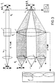
- An example of this technique applied to a simple imaging system is shown in Fig.1 from both a top and side view.
- the system comprises a collimating lens 1 and a focusing lens 2 of focal lengths f1 and f2, respectively, and is frequently used to couple a single laser diode to an optical fibre by focusing an image 3 of the laser emission stripe 4 onto the end of the fibre.
- the stripe 4 has a long dimension a in the x-axis and a short dimension b in the y-axis and is magnified by the lenses 1, 2 in both axes by a factor f2/f1.
- the diameter of the collimated beam 5a of a laser diode in the y-axis is typically three times that in the x-axis due to the difference in the numerical apertures of the emitted beam in the two axes. Therefore, and in accordance with US-A-4,905,690, two further parallel beams 5b, 5c (stacked in the x-axis direction) can be placed substantially within the aperture of the focusing lens 2. This increases the power and intensity of the image by a factor of 3.
- Fan et al teach a laser diode system for pumping Nd:YAG lasers (see Fig.3) in which a number of parallel laser diode beams 6a, 6b, 6c (stacked in the y-axis as opposed to the x-axis) are focussed into a gain medium of the Nd:YAG laser by a single pair at crossed cylindrical lenses (6, 7), each focusing independently in planes orthogonal to one another (xz and yz planes respectively).
- the focal lengths (f3, f4) of the focusing lenses may be optimised independently in the two axes. Therefore, the more critical long x-dimension of the image 3 may be optimised, within the constraints of the source and collimating lens properties and the numerical aperture of the focused beam, by selecting the focal length f3 of the cylindrical lens 6 focusing in that axis accordingly, eg. so that size of the image 3 does not exceed the target area in the x-direction.
- the aperture size is allowed to increase to accommodate a number of beams. This again necessitates an increase in the focal length f4 of the lens 7 in order to maintain the numerical aperture of the focused beam less than or equal to that of the fibre to avoid power loss.
- the aperture size of the y-axis focusing cylinder must become very large. Therefore, in order to maintain the same numerical aperture for the focused beams in the y-axis, the focal length of the y-axis focusing cylinder must also increase in proportion to the number of beams, which means that the distance between the diodes and the x-axis focusing cylinder becomes correspondingly large. This causes the problem of significant divergence of the beams over such a distance in the x direction.
- the numerical aperture of the focused beam in this axis has increased from 0.1NA to 0.6NA.
- Fan et al used sources with a 100 ⁇ m stripe dimension in the x-axis and a 4mm focal length collimating lens and this is the basis for the above divergence calculation.
- 200 or 500 ⁇ m sources are typically required and the divergence problem would be increased by a factor of 2 or 5 respectively.
- the present invention aims to overcome the above problems and, viewed from one aspect, provides a light source according to claim 1
- the images of the stripe sources preferably overlap one another within the target area, although it is envisaged that non-overlapping images could be provided if this is permitted by target area dimensions for the number of images required.
- the number of light beams which can be efficiently directed onto a target area such as the end of a fibre optic cable within a certain acceptance solid angle may be increased, in a similar manner to the Fan et al arrangement shown in Fig.3.
- the magnification of the image of each laser stripe may be increased in the thickness direction relative to the longitudinal direction which, according to the brightness theorem, results in a corresponding relative decrease in y-axis numerical aperture of each beam focused on the target area.
- This relative decrease in the numerical aperture enables a corresponding increase in the number of beams which can be fitted into the acceptance solid angle of the target without the beams overlapping as is similarly the case in the Fan et al arrangement shown in Fig.3.
- the present invention separates the anamorphic means of the optical system from the focusing means so that an inexpensive and easily available symmetrical lens may be used as the focusing means (it should be understood however that the generality of the invention is not affected if there is some degree of asymmetry in the focusing means).
- the separation between the collimating means and the focusing means can be kept relatively small even if the focal length of the focusing means is high, thereby minimising any divergence effects in the collimated beams (the above-mentioned 16 beams arrangement relating to the Fan et al system can be achieved by a system in accordance with the present invention with less than 100mm between the stripe light sources (e.g. laser diodes) and the focusing means, as compared with almost 1000mm between the source and the x-axis focusing cylinder in the Fan system).
- the stripe light sources e.g. laser diodes
- the anamorphic beam shaping means serves to increase the ratio of the x-axis dimension of the collimated beam relative to the y-axis dimension, and this may be achieved by expanding the beam width in the x-axis, reducing the beam width in the y-axis, or by a combination of both.
- the beam shaping means reduces the beam width in the y-axis then a further advantage exists over the Fan et al system in that the aperture size and focal length of the focusing means does not need to increase significantly as the number of combined beams increases, since instead of increasing the aperture of the lens as more beams are used, the width of the beams in the y-axis may be further reduced (this of course makes the image fatter in the y-axis but this is not critical for most applications). This allows the system to remain practical and compact even with a large number of beams.
- the beam shaping means anamorphically shapes the beams to produce beams of substantially elliptical cross-section having the major axis in their x-axis. Preferably this is achieved by increasing the width of the collimated beams in their x-axis.
- the maximum number of beams that can be efficiently combined for a particular target size and acceptance angle is roughly proportional (i.e. to the first order) to the anamorphic ratio A between the short dimension magnification and the long dimension magnification of the stripe.
- the magnification Mx of each stripe source in its long dimension may be selected so that the corresponding length of the overlapping image produced on the target matches the size of the target, i.e. the core diameter of the fibre optic cable.
- the anamorphic ratio A may then be selected such that it is greater than the ratio (A min) which will allow the combination of a required number N of beams (having regard to the power requirement) into the acceptance solid angle of the target without substantial angular overlap of the beams, but is less than a maximum value (A max) where the magnification My of each stripe in the short direction would cause the image of the laser stripe in the corresponding thickness direction to substantially exceed the size of the target in that direction (which would lead to power loss).
- a max Ty/(MxSy)
- the anamorphic ratio is preferably the same for each light source, e.g. laser diode, but may be different within the constraints of A min and A max. Individual sources may even have anamorphic ratios less than A min, provided that this is compensated for by other sources having an anamorphic ratio correspondingly greater than A min.
- the light from a greater number of light sources such as laser diodes can be efficiently coupled into a target area having a certain acceptance solid angle, such as a fibre optic cable or the retina of the eye, as compared with prior art systems, without the need for complex fibre optic cable bundles, complex fibre optic elements or lenses, or the need for multiple wavelengths with accurate wavelength control.
- a target area having a certain acceptance solid angle such as a fibre optic cable or the retina of the eye
- This latter point is particularly important where it may be required to irradiate a wavelength selective target, for example when pumping a Nd:YAG laser rod, which application is of course covered by the invention.
- the anamorphic imaging means may take a number of forms.
- the imaging means includes a collimating means for each laser beam, one or more anamorphic beam shaping means arranged downstream of the collimating means, and a substantially symmetrical focusing lens or an array of substantially symmetrical lenses to form the overlapping images of the laser stripes.
- the anamorphic beam shaping means may comprise a prism pair or a cylindrical telescope and may be arranged either to decrease beam width in the y direction and/or increase beam width in the x direction.
- Anamorphic beam shaping optics of this and other types for use with sources such as laser diodes are known in the art.
- a preferred embodiment of the invention comprises means upstream of the focusing lens or lenses for providing a closely packed but non-coincident bundle of beams which intersect the focusing lens or lenses and are focused thereby onto the target area.
- One embodiment of bundling means comprises a symmetrical array of mirrors adapted to be directed along the central optical axis of the focusing lens or lenses and arranged to receive incident beams in a cartwheel fashion and to reflect these along the optical axis in a closely packed, but non-coincident bundle.
- the bundle of beams need not of course be limited to the above cartwheel arrangement, and could take any form.
- the anamorphically shaped beams may be stacked into a linear array such as a 4 x 2 array. This could be done, for example, by arranging the beam shaping means of each beam one behind the other in a stepped manner so that the beams are not blocked by the beam shaping means in front.
- each beam which is focused onto the target area is itself formed of coincident beams from two or more laser diodes which have been combined by polarising and/or dichroic beam combiners.
- the power available will be equivalent to 2N laser diodes, if only polarising beams combiners are used, and will be more if dichroic beams combiners are used.
- a visible light source is also provided onto said target area by said focusing means.
- a visible source is useful where for example the source is used in an angioplasty device in which case the visible beam may be easily aimed.
- the visible source beam need not have the same characteristics as the other light sources and does not need to be anamorphically magnified.
- the invention has been discussed particularly with reference to laser diode sources. However, it may have application to other light sources having a similar output aspect ratio and numerical aperture characteristics to a laser diode.
- a pair of laser diodes have laser source stripes 8 of dimension Sx in the long dimension and Sy in the thickness direction.
- the sources each produce a divergent beam 9 whose numerical aperture is greater in the y axis than in the x axis.
- Each beam is collimated by a collimating lens 10 to provide a beam 11 of oval cross-section having outside dimensions Bx and By, with By being greater than Bx by a factor of about 3 ( Figures 4 and 5 are not to scale in this respect) owing to the difference in the source numerical aperture in the two axes as described.
- anamorphic prism pairs 12 Downstream of the collimating lenses 10 are arranged respective anamorphic prism pairs 12 which expand the beams 11 by a factor equivalent to the anamorphic ratio A in the x direction but have no effect on the beam thicknesses in the y direction. It will be appreciated that this relative increase in beam thickness results in a corresponding demagnification of the x-axis diameter of the image of each stripe relative to its y-axis diameter by a factor A produced by the downstream focusing lens discussed below.
- the anamorphic ratio A is 3 so that the beam cross-section downstream of the anamorphic prism pair is approximately circular.
- a polarising beam combiner After passing through the anamorphic prism pairs 12, the beams 11 are combined using a polarising beam combiner.
- This comprises a combining cube 13 formed of two prisms having their respective hypotenuses in contact, the interface 14 between the prisms being provided with a dielectric coating so that it will transmit light which is P polarised but reflect light that is S polarised.
- the light teams emitted by the laser diodes are both P polarised, and therefore a half wave plate 15 is arranged in the path of the upper beam shown in Figure 4, which is reflected through 90° by a further prism 16 onto the coated interface 14 and thereby onto a coaxial path with tine other beam which passes through the interface 14 (the halt wave plate 15 rotates the polarisation of the upper bean through 90°).
- a combined beam 16 is therefore produced.
- the illustrated embodiment of the invention comprises seven beam shaping and combining arrangements of the sort shown in figures 4 and 5. Six of these are arranged in a radial arrangement so that the combined beams 16 are projected inwardly in a cartwheel arrangement onto a bundling mirror 17 shown in Figures 6a and 6b.
- the bundling mirror 17 comprises a symmetrical array of reflecting surfaces 18 arranged to reflect each of the beams 16 to form a closely packed, non-coincident bundle of beams as shown in Figure 7b.
- the bundling mirror 17 includes a central aperture 19 whereby the combined beam 16 from a seventh beam shaping and combining means may be directed along the central axis of the bundle.
- the bundle of beams is directed onto a focusing lens 20 whereby each beam is focused onto the end of an optical fibre or other target area T of dimensions Tx and Ty whereby an image 21 of dimensions Ix and Iy is formed on the target area made up of overlapping images of all of the laser stripes.
- the maximum number of beams N which can be efficiently combined in this way without the beams intersecting one another for a particular target diameter and acceptance solid angle is proportional to the anamorphic ratio A between the x-axis magnification and y-axis magnification.
- the appropriate x-axis magnification is where the length of the image stripe Ix matches the target dimension Tx.
- the overall magnification depends on the anamorphic ratio A and on the relative focal lengths of the collimating and focusing lenses 10, 20.
- the magnification in the y-axis can be greater than the x-axis magnification up to the point where the image thickness Iy becomes too great for the particular target dimension Ty, i.e. up to a point where substantial power loss occurs as a result of the image not entirely intersecting the target.
- the increase in the maximum number of beams permissible is consequent upon numerical aperture reduction in the y-axis of each beam being focused onto the target area.
- the collimated beams have been shaped so that they are approximately circular in cross-section. This is of course not limiting and in a number of assemblies reduced to practice the beam is in fact shaped into an ellipse the major axis of which is in the x-axis. This is preferably achieved for the above embodiment by anamorphically expanding the collimated beam in the x-axis by four.
- the anamorphic prism pair is arranged to increase the beam cross-section in the x-axis and thereby reduce the magnification in the x-axis caused by the lenses 10, 20 whilst having no affect on magnification in the y-axis.
- the prisms can instead be arranged to decrease beam cross-section in the y-axis and thereby increase image magnification in that direction.
- Figs. 8 and 9 schematically show further embodiments of the invention in which both the x-axis dimension of the collimated beam 11 is expanded and the y-axis dimension is reduced.
- the anamorphic ratio is nine to allow three beams to be combined together, whilst in Fig.9 the anamorphic ratio is fifteen to allow five beams to be combined using the same size focusing lens as for the three beams.
- the size and focal length of the focusing lens 20 and the size of the fibre diameter in these two embodiments are different from those in the first embodiment.
- the focusing lens 20 would need to be increased in size about three times in order to adequately encompass the three beams (assuming that the beams are arranged in a line rather than in some more compact form). This would necessitate an increase in focal length of lens 20 by a factor of three to maintain the numerical aperture of the combined focused beam constant, e.g.
- the beam shaping means would then need to be adjusted to increase the width of the collimated beams in the x-axis by a further factor of three to nine so that the overall magnification of the image in the x-axis remains constant.
- sixteen beams are focused onto the end of a fibre.
- the beams are anamorphically expanded by a factor of four in the x-axis to produce a beam having an elliptical cross-section with the major axis in the x-axis, combined using polarising beam combiners, and then arranged into a 2 x 4 arrray to be focused by a lens onto the fibre end.
- the apparatus comprises a housing 100 bolted to a base 101.
- a 4 x 4 array of laser diode modules 102 is mounted within the housing 100 on the base 101.
- Each module 102 comprises a laser diode 103 with associated monitors/sensors and power supply leads, and a collimating lens 104 for collimating the laser beam.
- the provision of a module 102 comprising both the laser diode 103 and the collimating lens 104 allows the two elements to be accurately prealigned with one another before mounting on the base plate and prevents any subsequent misalignment.
- the laser diodes 103 are SDL - 2460 (Spectra Diode Labs., U.S.A.) or SLD 304 (Sony, Japan) having stripe dimensions of 200 x 1 ⁇ m, numerical apertures of 0.17 x 0.5 and a power output of 1 watt.
- the collimating lenses are Olympus AV-4647-3TM of 0.47 numerical aperture and 4.6 mm focal length.
- the laser modules 102 are grouped together in pairs, and above each pair is a beam shaping and combining unit 105 mounted to the side walls of the housing 100 by support means 106.
- Each unit 105 includes two anamorphic prisms pairs 107, one for each beam, which are SF-11 Littrow Prisms for 800 nm, which expand each beam in the x-axis by a factor of 4.0 and have no effect on the y-axis beam dimension.
- Each unit 105 also includes polarising beam combiner means 108 which are Melles Griot 03PBS062TM and which combine the beams together. The combined beams then reflect off of a prism 109, which also forms part of the unit 105, onto the focusing lens 110. As can be seen from Figs.
- the four units 105 on each side of the housing 100 are linearly aligned, but are positioned higher above their respective laser modules 102 the nearer they are to the back of the housing. This provides a vertical 1 x 4 array on each side of the housing 100 to produce an overall 2 x 4 array of beams which are focused by the lens 110 onto output fibre 111.
- Lens 110 is a aspheric singlet of 26 mm focal length, 30 mm diameter and 0.35 numerical aperture.
- the fibre is an Ensign Bickford HCSTM fibre of 400 ⁇ m diameter and 0.37 NA acceptance angle and is accurately positioned in relation to the focusing lens 110 on insertion into the housing 100.
- sensors 112 are provided for sensing whether or not the fibre is in position and for preventing energisation of the laser diodes should the fibre be absent (see Fig.10 and 13).
- Such a device produces a light source having a power output of 12.5W and image size of 300 x 6 ⁇ m.
- a beam 113 from a laser diode 114 which emits visible light, passes through a part of the lens 110 which is not occupied by the other beams (See Fig.11).
- the stripe image at the fibre will be 300 ⁇ m x 12.9 ⁇ m and each beam will occupy about 4% of the fibre acceptance solid angle.
- An ophthalmic photocoagulator is required to provide 2W into a 100 ⁇ m spot from laser diode sources of 0.5W with 100 ⁇ m x 1 ⁇ m stripes and 0.17 x 0.5 NA beam emission.
- the maximum acceptance angle of the eye is .2 NA.
- the anamorphic ratio A may be between 10 and 100.
- the spot size at the retina will be 100 ⁇ m by 10 ⁇ m.
Abstract
Description
- The present invention relates to light sources, and relates particularly, but not exclusively, to light sources comprising solid state laser diodes.
- Laser diodes are compact, robust, efficient and relatively inexpensive sources of laser light. It has therefore been proposed to use laser diodes as light energy sources in many applications in place of previously used gas lasers or solid state lasers such as Nd:YAG which are large and not easily portable. Such applications include body implantable angioplasty probes, ophthalmic treatments, contact laser surgery, etc.
- However, the power output available from a single laser diode is limited to a few watts. Furthermore, each diode emits from an elongated high aspect ratio "stripe" into a relatively large cone angle. The cone angle, i.e. the numerical aperture of the emitted beam, is smaller in the direction parallel to the long axis of the laser stripe (hereinafter called the x-axis) than in the direction perpendicular to the long axis of the stripe (y-axis).
- In view of the power limitation of a single laser diode, for many applications it is necessary to combine the outputs from a number of laser diodes. In any such system, the light from a number of laser diodes must be efficiently transmitted to a target area, which typically may have an aspect ratio which is lower than that of the laser stripe and which also may have a certain maximum acceptance cone or solid angle for efficient transmission or light to the target. For example, in applications such as angioplasty devices where light energy is transmitted through an optical fibre, the target area, i.e. the end of the fibre, is round, and the acceptance solid angle is the same In both axes and corresponds to the maximum numerical aperture of an incident beam which can be efficiently coupled into the fibre. A further example is treatment of the retina in the eye, where the light energy must be focussed onto a predetermined target area on the retina via the iris which imposes a maximum acceptance solid angle.
- Problems arise in practice in seeking to combine light from a plurality of laser diode sources such that the required power may be delivered to a predetermined target area within the constraints imposed by the efficient acceptance solid angle associated with the target or indeed with the delivery optics of the source itself.
- There has been a number of approaches to overcome the problem. It has been proposed to combine the beams from two laser diodes using a polarising beam combiner and to focus the combined beam onto the end of an optical fibre. It has also been proposed to minimise the diameter of the fibre in such an arrangement by anamorphically demagnifing the image of the laser stripe in its long dimension up to a point where the numerical apertures of the combined laser beam in both dimensions match the acceptance numerical aperture of the fibre. However, for either of these proposals the maximum power for each fibre is equivalent to that from only two laser diodes, and to achieve more power it is necessary to bundle a plurality of such fibres together. In certain applications this may not be an efficient solution in view of image to target size mis-match and in view of the complex fibre optics required. The bundling of a number of fibres together in this way also results in a loss of brightness and at high power can be prone to thermally induced damage. It has also been proposed to combine beams from a number of lasers of different wavelengths using wavelength selective mirrors. However, this is unsatisfactory in practice, in view in particular of the extreme temperature sensitivity of the wavelength of laser diodes. A further approach has been to form the end of optical fibres into an oblong shape to match more closely the laser diode stripe, but such fibres are expensive to produce and the coupling of light energy into each fibre is not particularly efficient.
- A still further attempt at providing a more powerful laser diode light source may be found in US-A-4,905,690 in which light beams from a number of laser diodes are arranged to have their axes parallel, and to be focussed onto a target area by a single focusing lens having a diameter sufficient to encompass the multiple beams. An example of this technique applied to a simple imaging system is shown in Fig.1 from both a top and side view. The system comprises a collimating lens 1 and a focusing lens 2 of focal lengths f1 and f2, respectively, and is frequently used to couple a single laser diode to an optical fibre by focusing an image 3 of the laser emission stripe 4 onto the end of the fibre. The stripe 4 has a long dimension a in the x-axis and a short dimension b in the y-axis and is magnified by the lenses 1, 2 in both axes by a factor f2/f1. The diameter of the collimated beam 5a of a laser diode in the y-axis is typically three times that in the x-axis due to the difference in the numerical apertures of the emitted beam in the two axes. Therefore, and in accordance with US-A-4,905,690, two further parallel beams 5b, 5c (stacked in the x-axis direction) can be placed substantially within the aperture of the focusing lens 2. This increases the power and intensity of the image by a factor of 3. However, if more power is required and the arrangement is therefore extended to include more than three beams, problems arise because it becomes necessary to increase the diameter of the focusing lens in order to encompass the extra beams (this is illustrated for five beams in Fig.2), and if the same numerical aperture or the focussed beam is to be maintained so that it stays less than or equal to the numerical aperture or the fibre to avoid power loss, then the focal length of the focusing lens must also be increased in direct proportion to the increased diameter. This increased focal length (by a factor of 5/3 in the case or Fig.2) increases the magnification of the stripe images by the same factor so that although the power has been increased, the size of the image has also been increased in the same proportion. This will result in power loss if the image is magnified to be larger than the target area, ie. the fibre end diameter.
- In "Scalable, end-pumped, diode-laser-pumped laser" (Optics Letters, Vol. 14, No.19, October 1, 1989), and in "Pump Source Requirements for End-Pump Lasers" (IEEE Journal of Quantum Electronics, Vol.26, No.2, February 1990), Fan et al teach a laser diode system for pumping Nd:YAG lasers (see Fig.3) in which a number of parallel laser diode beams 6a, 6b, 6c (stacked in the y-axis as opposed to the x-axis) are focussed into a gain medium of the Nd:YAG laser by a single pair at crossed cylindrical lenses (6, 7), each focusing independently in planes orthogonal to one another (xz and yz planes respectively). This allows the focal lengths (f3, f4) of the focusing lenses to be optimised independently in the two axes. Therefore, the more critical long x-dimension of the image 3 may be optimised, within the constraints of the source and collimating lens properties and the numerical aperture of the focused beam, by selecting the focal length f3 of the cylindrical lens 6 focusing in that axis accordingly, eg. so that size of the image 3 does not exceed the target area in the x-direction. In the less critical short y-dimension of the image 3, the aperture size is allowed to increase to accommodate a number of beams. This again necessitates an increase in the focal length f4 of the lens 7 in order to maintain the numerical aperture of the focused beam less than or equal to that of the fibre to avoid power loss. This increase in focal length again produces a commensurate increase in the y-dimenson of each image and reduction in the y-axis numerical apertures of each beam to allow more beams to fit into the acceptance cone angle of the target. Thus, and unlike in the US-A-4,905,690 system, if this system is extended to increase the number of beams focused on to the target area the numerical aperture of the focused beam nay be maintained without needing to increase the magnification of the image in the long x-axis but only in the less critical short y-axis. Therefore, this system allows higher powers to be achieved into a given fibre diameter than does US-A-4,905,690.
- This system does however have a number of disadvantages. First, for focused beams of reasonable numerical apertures, complex multi-element or aspheric cylindrical lenses will be required to reduce optical aberrations to an acceptable level and to compensate for aberrations in the y-axis imaging caused by the x-axis cylinder. Moreover, while multi-element or aspheric symmetrical lenses are standard practice in the optics industry, the manufacture of multi-element or aspheric cylindrical lenses is non-trivial and almost unknown in the optics industry.
- Second, in order to combine a reasonable number of beams, the aperture size of the y-axis focusing cylinder must become very large. Therefore, in order to maintain the same numerical aperture for the focused beams in the y-axis, the focal length of the y-axis focusing cylinder must also increase in proportion to the number of beams, which means that the distance between the diodes and the x-axis focusing cylinder becomes correspondingly large. This causes the problem of significant divergence of the beams over such a distance in the x direction. As an example, in their publications Fan et al combine 3 diodes using a 150 mm focal length 25mm aperture cylindrical lens for focusing in the y-axis, if this were increased to 16 beams under similar constraints, the aperture of the lens would increase to 155mm and its focal length to just under one metre (930mm). In the orthogonal (x-axis) plane the original 20mm focal length lens would still need to be used but because this lens is now more than 910mm from the diodes, the 25mrad divergence of the collimated beam in this axis (arising from the source size in this axis) will result in an increase in the beam dimension at the lens aperture from approximately 4mm in the case they illustrated in their publication to approximately 30mm, i.e. the numerical aperture of the focused beam in this axis has increased from 0.1NA to 0.6NA. For their demonstration Fan et al used sources with a 100µm stripe dimension in the x-axis and a 4mm focal length collimating lens and this is the basis for the above divergence calculation. For higher power sources, 200 or 500µm sources are typically required and the divergence problem would be increased by a factor of 2 or 5 respectively.
- Other high power laser sources are known from EP 0 310 711 A and Appl. Phys. Lett. 51 (16) 19 Oct. 1987, p 1212-1214.
- The present invention aims to overcome the above problems and, viewed from one aspect, provides a light source according to claim 1
- In accordance with the invention, the images of the stripe sources preferably overlap one another within the target area, although it is envisaged that non-overlapping images could be provided if this is permitted by target area dimensions for the number of images required.
- With such an arrangement the number of light beams which can be efficiently directed onto a target area such as the end of a fibre optic cable within a certain acceptance solid angle may be increased, in a similar manner to the Fan et al arrangement shown in Fig.3.
- This is on the assumption that the target area has a lower aspect ratio than that of the source e.g. laser stripes, since, if this is so, then the magnification of the image of each laser stripe may be increased in the thickness direction relative to the longitudinal direction which, according to the brightness theorem, results in a corresponding relative decrease in y-axis numerical aperture of each beam focused on the target area. This relative decrease in the numerical aperture enables a corresponding increase in the number of beams which can be fitted into the acceptance solid angle of the target without the beams overlapping as is similarly the case in the Fan et al arrangement shown in Fig.3.
- Unlike in the Fan et al system however, the present invention separates the anamorphic means of the optical system from the focusing means so that an inexpensive and easily available symmetrical lens may be used as the focusing means (it should be understood however that the generality of the invention is not affected if there is some degree of asymmetry in the focusing means).
- Moreover, the separation between the collimating means and the focusing means can be kept relatively small even if the focal length of the focusing means is high, thereby minimising any divergence effects in the collimated beams (the above-mentioned 16 beams arrangement relating to the Fan et al system can be achieved by a system in accordance with the present invention with less than 100mm between the stripe light sources (e.g. laser diodes) and the focusing means, as compared with almost 1000mm between the source and the x-axis focusing cylinder in the Fan system).
- The anamorphic beam shaping means serves to increase the ratio of the x-axis dimension of the collimated beam relative to the y-axis dimension, and this may be achieved by expanding the beam width in the x-axis, reducing the beam width in the y-axis, or by a combination of both. If the beam shaping means reduces the beam width in the y-axis then a further advantage exists over the Fan et al system in that the aperture size and focal length of the focusing means does not need to increase significantly as the number of combined beams increases, since instead of increasing the aperture of the lens as more beams are used, the width of the beams in the y-axis may be further reduced (this of course makes the image fatter in the y-axis but this is not critical for most applications). This allows the system to remain practical and compact even with a large number of beams.
- In a preferred embodiment, the beam shaping means anamorphically shapes the beams to produce beams of substantially elliptical cross-section having the major axis in their x-axis. Preferably this is achieved by increasing the width of the collimated beams in their x-axis.
- The maximum number of beams that can be efficiently combined for a particular target size and acceptance angle is roughly proportional (i.e. to the first order) to the anamorphic ratio A between the short dimension magnification and the long dimension magnification of the stripe.
- Thus, for any particular target area, such as the end of a fibre optic cable, the magnification Mx of each stripe source in its long dimension may be selected so that the corresponding length of the overlapping image produced on the target matches the size of the target, i.e. the core diameter of the fibre optic cable. The anamorphic ratio A may then be selected such that it is greater than the ratio (A min) which will allow the combination of a required number N of beams (having regard to the power requirement) into the acceptance solid angle of the target without substantial angular overlap of the beams, but is less than a maximum value (A max) where the magnification My of each stripe in the short direction would cause the image of the laser stripe in the corresponding thickness direction to substantially exceed the size of the target in that direction (which would lead to power loss).
- Thus, for any particular value of Mx,
- Ty =
- target size in the direction of the image dimension corresponding to the short dimension of the stripe-shaped source
- Sy =
- stripe source width in its short dimension.
- It can also be shown that
- N =
- number of beams to be combined (in view of power requirement)
- Θ =
- emission solid angle of stripe
- =
- acceptance solid angle of target
- δ =
- maximum practical beam packing fraction i.e. the fraction of solid angle that is occupied by the stripe-shaped source beams, for a particular value of N
- Mx =
- magnification of stripe source in long dimension.
- The anamorphic ratio is preferably the same for each light source, e.g. laser diode, but may be different within the constraints of A min and A max. Individual sources may even have anamorphic ratios less than A min, provided that this is compensated for by other sources having an anamorphic ratio correspondingly greater than A min.
- In accordance with the invention, the light from a greater number of light sources such as laser diodes can be efficiently coupled into a target area having a certain acceptance solid angle, such as a fibre optic cable or the retina of the eye, as compared with prior art systems, without the need for complex fibre optic cable bundles, complex fibre optic elements or lenses, or the need for multiple wavelengths with accurate wavelength control. This latter point is particularly important where it may be required to irradiate a wavelength selective target, for example when pumping a Nd:YAG laser rod, which application is of course covered by the invention.
- The anamorphic imaging means may take a number of forms. In one embodiment, the imaging means includes a collimating means for each laser beam, one or more anamorphic beam shaping means arranged downstream of the collimating means, and a substantially symmetrical focusing lens or an array of substantially symmetrical lenses to form the overlapping images of the laser stripes. The anamorphic beam shaping means may comprise a prism pair or a cylindrical telescope and may be arranged either to decrease beam width in the y direction and/or increase beam width in the x direction. Anamorphic beam shaping optics of this and other types for use with sources such as laser diodes are known in the art.
- A preferred embodiment of the invention comprises means upstream of the focusing lens or lenses for providing a closely packed but non-coincident bundle of beams which intersect the focusing lens or lenses and are focused thereby onto the target area. One embodiment of bundling means comprises a symmetrical array of mirrors adapted to be directed along the central optical axis of the focusing lens or lenses and arranged to receive incident beams in a cartwheel fashion and to reflect these along the optical axis in a closely packed, but non-coincident bundle.
- The bundle of beams need not of course be limited to the above cartwheel arrangement, and could take any form. For example, the anamorphically shaped beams may be stacked into a linear array such as a 4 x 2 array. This could be done, for example, by arranging the beam shaping means of each beam one behind the other in a stepped manner so that the beams are not blocked by the beam shaping means in front.
- In a preferred embodiment, each beam which is focused onto the target area is itself formed of coincident beams from two or more laser diodes which have been combined by polarising and/or dichroic beam combiners. In this way, for a number N of beams focused onto the target area the power available will be equivalent to 2N laser diodes, if only polarising beams combiners are used, and will be more if dichroic beams combiners are used.
- In a further preferred embodiment, a visible light source is also provided onto said target area by said focusing means. Such a visible source is useful where for example the source is used in an angioplasty device in which case the visible beam may be easily aimed. The visible source beam need not have the same characteristics as the other light sources and does not need to be anamorphically magnified.
- The invention has been discussed particularly with reference to laser diode sources. However, it may have application to other light sources having a similar output aspect ratio and numerical aperture characteristics to a laser diode.
- Embodiments of the invention will now be described, by way of example only, with reference to the accompanying drawings, in which:
- Figure 1 is a schematic representation, in both the long and short axes of the stripes, of a prior art system for focusing three laser diode beams into an optical fibre;
- Figure 2 is a schematic representation in both axes of a system similar to that in Figure 1, but with five beams being focused into a fibre;
- Figure 3 is a schematic representation in both axes of a prior art system for combining a number of laser diode beams to pump a Nd:YAG laser;
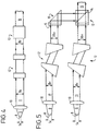
- Figure 4 shows means in accordance with the present invention for anamorphically shaping and combining the beams from two laser diodes viewed along the short axis of the laser stripes (y-axis);
- Figure 5 shows the arrangement of Figure 1 viewed along the long axis of the laser stripes (x-axis);
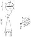
- Figures 6a and 6b are front elevational and cross-sectional views of a means for bundling seven combined light beams produced from respective beam shaping and combining means shown in Figures 4 and 5;
- Figures 7a and 7b show schematically the bundle of beams impinging on and being focused by a focusing lens onto the end of a fibre optic cable to produce overlapping images of the laser stripes;
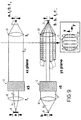
- Figure 8 is a schematic representation in both the long and short axes of the laser stripes of a second embodiment of the present invention in which three beams are combined;
- Figure 9 is a similar representation to that of figure 8, but in this case five beams are combined,
- Figure 10 is a cutaway side elevation view of apparatus in accordance with a further embodiment of the present invention,
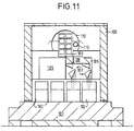
- Figure 11 is a cutaway front elevation view of the apparatus of Figure 10,
- Figure 12 is a plan view of a base plate of the apparatus of Figure 10,
- Figure 13 is a front elevation of the apparatus of Figure 10, and
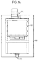
- Figure 14 is a top view of the apparatus of Figure 10.
-
- Referring firstly to Figures 4 and 5 (which are not to scale), a pair of laser diodes have laser source stripes 8 of dimension Sx in the long dimension and Sy in the thickness direction. The sources each produce a divergent beam 9 whose numerical aperture is greater in the y axis than in the x axis. Each beam is collimated by a collimating lens 10 to provide a beam 11 of oval cross-section having outside dimensions Bx and By, with By being greater than Bx by a factor of about 3 (Figures 4 and 5 are not to scale in this respect) owing to the difference in the source numerical aperture in the two axes as described. Downstream of the collimating lenses 10 are arranged respective anamorphic prism pairs 12 which expand the beams 11 by a factor equivalent to the anamorphic ratio A in the x direction but have no effect on the beam thicknesses in the y direction. It will be appreciated that this relative increase in beam thickness results in a corresponding demagnification of the x-axis diameter of the image of each stripe relative to its y-axis diameter by a factor A produced by the downstream focusing lens discussed below. In the illustrated example the anamorphic ratio A is 3 so that the beam cross-section downstream of the anamorphic prism pair is approximately circular.
- After passing through the anamorphic prism pairs 12, the beams 11 are combined using a polarising beam combiner. This comprises a combining cube 13 formed of two prisms having their respective hypotenuses in contact, the interface 14 between the prisms being provided with a dielectric coating so that it will transmit light which is P polarised but reflect light that is S polarised. The light teams emitted by the laser diodes are both P polarised, and therefore a half wave plate 15 is arranged in the path of the upper beam shown in Figure 4, which is reflected through 90° by a further prism 16 onto the coated interface 14 and thereby onto a coaxial path with tine other beam which passes through the interface 14 (the halt wave plate 15 rotates the polarisation of the upper bean through 90°). A combined beam 16 is therefore produced.
- The illustrated embodiment of the invention comprises seven beam shaping and combining arrangements of the sort shown in figures 4 and 5. Six of these are arranged in a radial arrangement so that the combined beams 16 are projected inwardly in a cartwheel arrangement onto a bundling mirror 17 shown in Figures 6a and 6b. The bundling mirror 17 comprises a symmetrical array of reflecting surfaces 18 arranged to reflect each of the beams 16 to form a closely packed, non-coincident bundle of beams as shown in Figure 7b. The bundling mirror 17 includes a central aperture 19 whereby the combined beam 16 from a seventh beam shaping and combining means may be directed along the central axis of the bundle.
- As shown in Figures 7a and 7b the bundle of beams is directed onto a focusing lens 20 whereby each beam is focused onto the end of an optical fibre or other target area T of dimensions Tx and Ty whereby an image 21 of dimensions Ix and Iy is formed on the target area made up of overlapping images of all of the laser stripes. As described above, the maximum number of beams N which can be efficiently combined in this way without the beams intersecting one another for a particular target diameter and acceptance solid angle is proportional to the anamorphic ratio A between the x-axis magnification and y-axis magnification. For any particular target size, the appropriate x-axis magnification is where the length of the image stripe Ix matches the target dimension Tx. The overall magnification depends on the anamorphic ratio A and on the relative focal lengths of the collimating and focusing lenses 10, 20. The magnification in the y-axis can be greater than the x-axis magnification up to the point where the image thickness Iy becomes too great for the particular target dimension Ty, i.e. up to a point where substantial power loss occurs as a result of the image not entirely intersecting the target. The increase in the maximum number of beams permissible is consequent upon numerical aperture reduction in the y-axis of each beam being focused onto the target area.
- In the above embodiment, the collimated beams have been shaped so that they are approximately circular in cross-section. This is of course not limiting and in a number of assemblies reduced to practice the beam is in fact shaped into an ellipse the major axis of which is in the x-axis. This is preferably achieved for the above embodiment by anamorphically expanding the collimated beam in the x-axis by four.
- Further in the above embodiment the anamorphic prism pair is arranged to increase the beam cross-section in the x-axis and thereby reduce the magnification in the x-axis caused by the lenses 10, 20 whilst having no affect on magnification in the y-axis. In an alternative embodiment the prisms can instead be arranged to decrease beam cross-section in the y-axis and thereby increase image magnification in that direction. With such an arrangement, if the anamorphic ratio and target size was to be the same as that shown in the illustrated embodiment, then the focal length of the focusing lens would be reduced by a factor of three, whereby the image size and numerical aperture of each beam 16 being focussed onto the target would remain the same.
- Figs. 8 and 9 schematically show further embodiments of the invention in which both the x-axis dimension of the collimated beam 11 is expanded and the y-axis dimension is reduced. In Fig.8, the anamorphic ratio is nine to allow three beams to be combined together, whilst in Fig.9 the anamorphic ratio is fifteen to allow five beams to be combined using the same size focusing lens as for the three beams. It should be noted that the size and focal length of the focusing lens 20 and the size of the fibre diameter in these two embodiments are different from those in the first embodiment.
- If it were required to focus three beams on to a fibre having a diameter as in Figures 8 and 9 by merely increasing the x-axis beam width, as in the first embodiment, then the focusing lens 20 would need to be increased in size about three times in order to adequately encompass the three beams (assuming that the beams are arranged in a line rather than in some more compact form). This would necessitate an increase in focal length of lens 20 by a factor of three to maintain the numerical aperture of the combined focused beam constant, e.g. below or equal to the acceptance angle of the fibre to avoid power loss, and the beam shaping means would then need to be adjusted to increase the width of the collimated beams in the x-axis by a further factor of three to nine so that the overall magnification of the image in the x-axis remains constant.
- In a still further embodiment, the apparatus for which is shown in Figs. 10 to 14, sixteen beams are focused onto the end of a fibre. The beams are anamorphically expanded by a factor of four in the x-axis to produce a beam having an elliptical cross-section with the major axis in the x-axis, combined using polarising beam combiners, and then arranged into a 2 x 4 arrray to be focused by a lens onto the fibre end.
- Referring to Figs.10 to 14, the apparatus comprises a housing 100 bolted to a base 101. A 4 x 4 array of laser diode modules 102 is mounted within the housing 100 on the base 101. Each module 102 comprises a laser diode 103 with associated monitors/sensors and power supply leads, and a collimating lens 104 for collimating the laser beam. The provision of a module 102 comprising both the laser diode 103 and the collimating lens 104 allows the two elements to be accurately prealigned with one another before mounting on the base plate and prevents any subsequent misalignment.
- The laser diodes 103 are SDL - 2460 (Spectra Diode Labs., U.S.A.) or SLD 304 (Sony, Japan) having stripe dimensions of 200 x 1 µm, numerical apertures of 0.17 x 0.5 and a power output of 1 watt. The collimating lenses are Olympus AV-4647-3™ of 0.47 numerical aperture and 4.6 mm focal length.
- The laser modules 102 are grouped together in pairs, and above each pair is a beam shaping and combining unit 105 mounted to the side walls of the housing 100 by support means 106.
- Each unit 105 includes two anamorphic prisms pairs 107, one for each beam, which are SF-11 Littrow Prisms for 800 nm, which expand each beam in the x-axis by a factor of 4.0 and have no effect on the y-axis beam dimension. Each unit 105 also includes polarising beam combiner means 108 which are Melles Griot 03PBS062™ and which combine the beams together. The combined beams then reflect off of a prism 109, which also forms part of the unit 105, onto the focusing lens 110. As can be seen from Figs. 10 and 11, the four units 105 on each side of the housing 100 are linearly aligned, but are positioned higher above their respective laser modules 102 the nearer they are to the back of the housing. This provides a vertical 1 x 4 array on each side of the housing 100 to produce an overall 2 x 4 array of beams which are focused by the lens 110 onto output fibre 111.
- Lens 110 is a aspheric singlet of 26 mm focal length, 30 mm diameter and 0.35 numerical aperture. The fibre is an Ensign Bickford HCS™ fibre of 400 µm diameter and 0.37 NA acceptance angle and is accurately positioned in relation to the focusing lens 110 on insertion into the housing 100. For safety, sensors 112 are provided for sensing whether or not the fibre is in position and for preventing energisation of the laser diodes should the fibre be absent (see Fig.10 and 13).
- Such a device produces a light source having a power output of 12.5W and image size of 300 x 6 µm.
- In order to be able to aim the beam provided through the fibre 111, a beam 113 from a laser diode 114, which emits visible light, passes through a part of the lens 110 which is not occupied by the other beams (See Fig.11).
- A laser diode source is required to couple 25W into a 300µm core diameter optical fibre having a 0.32 NA acceptance using 1W laser diode sources with stripe dimensions of 200µm x 1µm and emission numerical apertures in the x and y axes of .17 and 0.5 respectively. Assuming 80% optical efficiency, 32 laser diodes are required and the number N of combined beams to be focussed onto the end of the cable is 16. The emission solid angle is therefore Θ = 0.085, and the acceptance solid angle of the target is approximately = 0.10. For a selected maximum beam packing fraction δ = 0.7, Ty = 300, Sy =1 and Mx =1.5, the anamorphic ratio must be between 8.6 and 200 using the equations referred to above.
- For the minimum value of A = 8.6, the stripe image at the fibre will be 300µm x 12.9µm and each beam will occupy about 4% of the fibre acceptance solid angle.
- At the other extreme, if A = 200 then the stripe image at the fibre will be 300 µm by 300 µm, and each beam will occupy only about 0.2% of the acceptance solid angle. In this case the square stripe image is not well matched to the circular fibre core and power would thereby be lost. However, ignoring this effect, when A = 200, a total of 370 beams could theoretically be transmitted into the fibre giving a maximum power of 580 W where each beam is a combined one assuming 80% optical efficiency and a maximum practical beam packing fraction δ=0.7.
- An ophthalmic photocoagulator is required to provide 2W into a 100µm spot from laser diode sources of 0.5W with 100µm x 1µm stripes and 0.17 x 0.5 NA beam emission. The maximum acceptance angle of the eye is .2 NA. Assuming 70% optical efficiency, 6 diodes are required which are polarisation combined into three beams (N=3).
- For a 100µm spot, Mx = 1, emission solid angle Θ = 0.085, acceptance solid angle = 0.04, then for a selected maximum packing fraction δ = 0.7, the anamorphic ratio A may be between 10 and 100.
- For A = 10 the spot size at the retina will be 100 µm by 10 µm.
Claims (19)
- A light source for illuminating a predetermined target area (T;111) within a certain light acceptance solid angle associated with the target area (T;111), said light source comprising a plurality of stripe-shaped light sources (8;103), each having a long dimension (Sx) and a short dimension (Sy) and emitting a beam of light (9) having an x-axis and a y-axis corresponding respectively to the long and short stripe-shaped source dimensions, and imaging means (10,20;104,110) for collimating and focusing said beams (9) to produce images (21) of the stripe-shaped sources (8;103) substantially within the target area (T;111), said imaging means including anamorphic beam shaping means (12;107) for relatively increasing the width (Bx) of each beam (11) in its x-axis with respect to the width (By) of each beam (11) in its y-axis, and focusing means (20;110) arranged between the beam shaping means (12;107) and the target (T;111) and having substantially equal focal lengths in the two axes, the imaging means (10,12,20;104,107,110) being arranged such that the resulting anamorphic ratio between the magnification of each stripe-shaped source (8;103) in the short dimension and in the long dimension is greater than one, characterised in that the imaging means are arranged such that the images (21) are produced by light beams (16) which converge onto the target area (T;111) but which occupy substantially different regions within the target area acceptance solid angle.
- A light source as claimed in claim 1, wherein the images (21) of the stripe-shaped sources (8;103) overlap one another within the target area (T;111).
- A light source as claimed in claim 1 or 2, wherein said beam shaping means (12;107) anamorphically shapes said beams (11) to produce beams (16) of substantially elliptical cross-section having their major axis in their x-axis.
- A light source as claimed in claim 1, 2 or 3, wherein said beam shaping means (12;107) reduces the width of the beams (11) in their y-axis.
- A light source as claimed in claim 1, 2 or 3, wherein said beam shaping means (12;107) increases the width of the beams (11) in their x-axis.
- A light source as claimed in any preceding claim, wherein the magnification of each stripe-shaped source (8) in its long dimension is selected so that the corresponding length (Ix) of the image (21) produced on the target area (T) substantially matches the size (Tx) of the target area (T) in that image length direction.
- A light source as claimed in any preceding claim, wherein the anamorphic ratio A of at least some of the stripe-shaped sources (8;103) is substantially in the range
- Ty =
- target size in the direction of the image dimension corresponding to the short dimension of the stripe-shaped source
- Sy =
- stripe-shaped source width in its short dimension
- N =
- number of beams to be combined (in view of power requirement)
- Θ =
- emission solid angle of stripe-shaped source
- =
- acceptance solid angle of target
- δ =
- maximum practical beam packing fraction
- Mx =
- magnification of stripe-shaped source in long dimension.
- A light source as claimed in any preceding claim, wherein the imaging means includes a collimating means (10) for each beam (9), one or more anamorphic beam shaping means (12) arranged downstream of the collimating means (10) and a generally symmetrical focusing lens (20) or array of generally symmetrical lenses to form the images (21) of the stripe-shaped sources (8).
- A light source as claimed in claim 8, wherein said anamorphic beam shaping means comprises a prism pair (12).
- A light source as claimed in claim 8, wherein said anamorphic beam shaping means comprises a cylindrical telescope.
- A light source as claimed in any preceding claim, wherein said light source comprises means (17;106) upstream of the focusing means (20) for providing a closely packed bundle of non-coincident beams (16) which are acted on by the focusing means (20) and are focused thereby onto the target area (T;111).
- A light source as claimed in claim 11, wherein said bundling means (17) comprises a symmetrical array of reflectors arranged to direct a light beam (16) parallel to the central optical axis of the focusing lens (20) or lenses and arranged to receive incident beams in a cartwheel fashion and to reflect these along the optical axis.
- A light source as claimed in claim 11, wherein said bundling means comprises a number of reflectors/prisms (109) stepped from one another to form one or more linear arrays.
- A light source as claimed in any preceding claim, wherein each beam (16) which is focused onto the target area is itself formed of coincident beams (11) from two or more stripe-shaped sources (8) which have been combined by polarising and/or dichroic beam combiners (13).
- A light source as claimed in claim 14, wherein each of the stripe-shaped sources (103) is provided as a module (102) incorporating its own collimating lens (104) and each of the beam shaping means is provided as a separate unit (105) which incorporates the beam combiners (108) for the two or more stripe-shaped sources (103) to be combined.
- A light source as claimed in any preceding claim, wherein a visible light source (113) is focused on to the target area (111) through a portion of the focusing means (110) not occupied by the other beams.
- A light source as claimed in any preceding claim, wherein the target area is an end of an optical fibre (111).
- A light source as claimed in claim 17, further comprising mounting means for mounting an optical fibre (111) thereto.
- A light source as claimed in claim 18, wherein an optical fibre (111) is mounted to said mounting means.
Applications Claiming Priority (5)
| Application Number | Priority Date | Filing Date | Title |
|---|---|---|---|
| GB9016857 | 1990-08-01 | ||
| GB909016857A GB9016857D0 (en) | 1990-08-01 | 1990-08-01 | High power light source |
| GB909020904A GB9020904D0 (en) | 1990-08-01 | 1990-09-26 | High power light source |
| GB9020904 | 1990-09-26 | ||
| PCT/GB1991/001310 WO1992002844A1 (en) | 1990-08-01 | 1991-08-01 | High power light source |
Publications (3)
| Publication Number | Publication Date |
|---|---|
| EP0541658A1 EP0541658A1 (en) | 1993-05-19 |
| EP0541658B1 true EP0541658B1 (en) | 2000-03-15 |
| EP0541658B2 EP0541658B2 (en) | 2004-01-21 |
Family
ID=26297420
Family Applications (1)
| Application Number | Title | Priority Date | Filing Date |
|---|---|---|---|
| EP91914168A Expired - Lifetime EP0541658B2 (en) | 1990-08-01 | 1991-08-01 | High power light source |
Country Status (13)
| Country | Link |
|---|---|
| US (2) | US5319528A (en) |
| EP (1) | EP0541658B2 (en) |
| JP (1) | JP3078836B2 (en) |
| AT (1) | ATE190733T1 (en) |
| AU (1) | AU649707B2 (en) |
| BR (1) | BR9106718A (en) |
| CA (1) | CA2088497C (en) |
| DE (1) | DE69132049T3 (en) |
| DK (1) | DK0541658T3 (en) |
| ES (1) | ES2142803T3 (en) |
| GB (1) | GB2261528B (en) |
| GR (1) | GR3033564T3 (en) |
| WO (1) | WO1992002844A1 (en) |
Families Citing this family (62)
| Publication number | Priority date | Publication date | Assignee | Title |
|---|---|---|---|---|
| JP3078836B2 (en) * | 1990-08-01 | 2000-08-21 | ダイオメド・リミテツド | High energy light source |
| GB9221104D0 (en) * | 1992-10-07 | 1992-11-18 | Diomed Ltd | Laser diode drive circuit |
| GB9324589D0 (en) * | 1993-11-30 | 1994-01-19 | Univ Southampton | Beam shaping device |
| EP0660157A1 (en) * | 1993-12-20 | 1995-06-28 | Agfa-Gevaert N.V. | Device for combining laser beams in a common light spot |
| US5589684A (en) * | 1994-06-28 | 1996-12-31 | Sdl, Inc. | Multiple diode lasers stabilized with a fiber grating |
| US5841797A (en) * | 1994-06-28 | 1998-11-24 | Ventrudo; Brian F. | Apparatus for stabilizing multiple laser sources and their application |
| US5554153A (en) * | 1994-08-29 | 1996-09-10 | Cell Robotics, Inc. | Laser skin perforator |
| US5665305A (en) * | 1995-11-13 | 1997-09-09 | Belliveau; Richard S. | Lighting system with multiple beam shapes |
| JP3369404B2 (en) * | 1996-06-14 | 2003-01-20 | 三菱電機株式会社 | Light trigger thyristor |
| US6013025A (en) * | 1996-07-11 | 2000-01-11 | Micro Medical Devices, Inc. | Integrated illumination and imaging system |
| US6331692B1 (en) * | 1996-10-12 | 2001-12-18 | Volker Krause | Diode laser, laser optics, device for laser treatment of a workpiece, process for a laser treatment of workpiece |
| US5980066A (en) * | 1997-06-04 | 1999-11-09 | High End Systems, Inc. | Lighting system with multiple beam shapes |
| US6365024B1 (en) * | 1997-06-30 | 2002-04-02 | Spectrumedix Corporation | Motorized positioning apparatus having coaxial carrousels |
| IL142956A0 (en) * | 1998-11-04 | 2002-04-21 | Laserlab Res Ltd | Light-emitting adder |
| US7027691B1 (en) | 1999-10-05 | 2006-04-11 | Visteon Global Technologies, Inc. | Light coupling and distribution system |
| RU2163048C1 (en) * | 2000-01-24 | 2001-02-10 | РЕЙТЭК Лазер Индастрис Лтд. | Radiation source built around laser diodes |
| RU2172972C1 (en) * | 2000-01-27 | 2001-08-27 | РЕЙТЭК Лазер Индастрис Лтд. | Emitting adder |
| US6423925B1 (en) * | 2000-02-17 | 2002-07-23 | Universal Laser Systems, Inc. | Apparatus and method for combining multiple laser beams in laser material processing systems |
| US6424670B1 (en) | 2000-02-17 | 2002-07-23 | Universal Laser Systems, Inc. | Apparatus and method for making laser sources and laser platforms interchangeable and interfaceable |
| US6531681B1 (en) * | 2000-03-27 | 2003-03-11 | Ultratech Stepper, Inc. | Apparatus having line source of radiant energy for exposing a substrate |
| US6485163B1 (en) * | 2000-10-13 | 2002-11-26 | Neville Hanchett | Multi-position laser light projector |
| US6434284B1 (en) * | 2000-12-07 | 2002-08-13 | Corning Incorporated | Beam converter for enhancing brightness of polarized light sources |
| US6646669B2 (en) * | 2000-12-14 | 2003-11-11 | Creo Inc. | Multimode multi-track optical recording system |
| US6987240B2 (en) * | 2002-04-18 | 2006-01-17 | Applied Materials, Inc. | Thermal flux processing by scanning |
| US7005601B2 (en) | 2002-04-18 | 2006-02-28 | Applied Materials, Inc. | Thermal flux processing by scanning |
| JP2004047351A (en) * | 2002-07-15 | 2004-02-12 | Koito Mfg Co Ltd | Vehicular lighting fixture |
| KR101163682B1 (en) | 2002-12-20 | 2012-07-09 | 맷슨 테크날러지 캐나다 인코퍼레이티드 | Apparatus and method for supporting a workpiece |
| KR100474430B1 (en) * | 2002-12-30 | 2005-03-10 | 삼성전자주식회사 | Multi-beam laser scanning unit |
| US6870195B2 (en) * | 2003-02-21 | 2005-03-22 | Agilent Technologies, Inc. | Array of discretely formed optical signal emitters for multi-channel communication |
| GB0312443D0 (en) * | 2003-05-30 | 2003-07-09 | Newoptics Ltd | Optical multiplexer |
| WO2006018016A2 (en) | 2004-08-18 | 2006-02-23 | Arctos Showlasertechnik E. Kfm | Laser devices for generating laser beams |
| DE102004040107A1 (en) * | 2004-08-18 | 2006-02-23 | Arctos Showlasertechnik E.Kfm. | Laser device for generating red laser beam e.g. in advertising and animation etc, uses first and second laser part-beam devices |
| WO2008058397A1 (en) | 2006-11-15 | 2008-05-22 | Mattson Technology Canada, Inc. | Systems and methods for supporting a workpiece during heat-treating |
| EP2003484B1 (en) * | 2007-06-12 | 2018-04-11 | Lumentum Operations LLC | A Light Source |
| DE102007045845A1 (en) * | 2007-09-26 | 2009-04-09 | Arctos Showlasertechnik E.Kfm. | laser device |
| US7733932B2 (en) * | 2008-03-28 | 2010-06-08 | Victor Faybishenko | Laser diode assemblies |
| WO2009137940A1 (en) | 2008-05-16 | 2009-11-19 | Mattson Technology Canada, Inc. | Workpiece breakage prevention method and apparatus |
| US7773655B2 (en) * | 2008-06-26 | 2010-08-10 | Vadim Chuyanov | High brightness laser diode module |
| US9244235B2 (en) * | 2008-10-17 | 2016-01-26 | Foro Energy, Inc. | Systems and assemblies for transferring high power laser energy through a rotating junction |
| DE102008056128B4 (en) * | 2008-11-06 | 2010-10-07 | Trumpf Laser Gmbh + Co. Kg | Optics for focusing diode laser radiation |
| US8000358B2 (en) * | 2009-04-20 | 2011-08-16 | Emcore Corporation | Power monitoring system for a parallel optical transmitter |
| US8437086B2 (en) | 2010-06-30 | 2013-05-07 | Jds Uniphase Corporation | Beam combining light source |
| US8427749B2 (en) | 2010-06-30 | 2013-04-23 | Jds Uniphase Corporation | Beam combining light source |
| CN102255238B (en) * | 2010-09-17 | 2013-03-20 | 武汉高晟知光科技有限公司 | Packaging structure of semiconductor laser device and application device thereof |
| US8432945B2 (en) | 2010-09-30 | 2013-04-30 | Victor Faybishenko | Laser diode combiner modules |
| US8891579B1 (en) | 2011-12-16 | 2014-11-18 | Nlight Photonics Corporation | Laser diode apparatus utilizing reflecting slow axis collimators |
| US9018108B2 (en) | 2013-01-25 | 2015-04-28 | Applied Materials, Inc. | Low shrinkage dielectric films |
| JP6393466B2 (en) * | 2013-10-02 | 2018-09-19 | 株式会社島津製作所 | Light emitting device |
| US9647416B2 (en) | 2013-12-23 | 2017-05-09 | Lumentum Operations Llc | Bidirectional long cavity semiconductor laser for improved power and efficiency |
| US9705289B2 (en) | 2014-03-06 | 2017-07-11 | Nlight, Inc. | High brightness multijunction diode stacking |
| WO2015134931A1 (en) | 2014-03-06 | 2015-09-11 | Nlight Photonics Corporation | High brightness multijunction diode stacking |
| JP6349792B2 (en) * | 2014-03-07 | 2018-07-04 | 富士通オプティカルコンポーネンツ株式会社 | Optical transmitter |
| CA2917585C (en) | 2014-05-15 | 2016-09-27 | Mtt Innovation Incorporated | Optimizing drive schemes for multiple projector systems |
| JP6791840B2 (en) | 2014-08-14 | 2020-11-25 | エムティティ イノベーション インコーポレイテッドMtt Innovation Incorporated | light source |
| US10761276B2 (en) | 2015-05-15 | 2020-09-01 | Nlight, Inc. | Passively aligned crossed-cylinder objective assembly |
| JP6154965B2 (en) * | 2015-06-19 | 2017-06-28 | 株式会社アマダミヤチ | Laser unit and laser device |
| JP6998774B2 (en) * | 2016-01-13 | 2022-02-10 | 古河電気工業株式会社 | Semiconductor laser devices, chip-on-submounts, and semiconductor laser modules |
| WO2017143089A1 (en) | 2016-02-16 | 2017-08-24 | Nlight, Inc. | Passively aligned single element telescope for improved package brightness |
| US10153608B2 (en) | 2016-03-18 | 2018-12-11 | Nlight, Inc. | Spectrally multiplexing diode pump modules to improve brightness |
| WO2018119125A1 (en) | 2016-12-23 | 2018-06-28 | Nlight, Inc. | Low cost optical pump laser package |
| US10763640B2 (en) | 2017-04-24 | 2020-09-01 | Nlight, Inc. | Low swap two-phase cooled diode laser package |
| EP3750218A4 (en) | 2018-02-06 | 2021-11-03 | Nlight, Inc. | Diode laser apparatus with fac lens out-of-plane beam steering |
Family Cites Families (59)
| Publication number | Priority date | Publication date | Assignee | Title |
|---|---|---|---|---|
| GB213787A (en) * | 1923-05-01 | 1924-04-10 | Alec John Gerrard | Box strapping machine |
| US3273072A (en) * | 1965-01-18 | 1966-09-13 | American Optical Corp | Laser amplifier with variable gain control |
| US3590248A (en) * | 1965-04-13 | 1971-06-29 | Massachusetts Inst Technology | Laser arrays |
| US3736518A (en) * | 1971-11-22 | 1973-05-29 | Rca Corp | Maser incorporating crystal having f-centers |
| JPS51139644U (en) * | 1975-04-30 | 1976-11-10 | ||
| US4318594A (en) * | 1977-02-15 | 1982-03-09 | Canon Kabushiki Kaisha | Beam shaping optical system |
| US4185891A (en) * | 1977-11-30 | 1980-01-29 | Grumman Aerospace Corporation | Laser diode collimation optics |
| US4293827A (en) * | 1979-09-14 | 1981-10-06 | Jersey Nuclear-Avco Isotopes, Inc. | Multiwavelength dye laser |
| GB2069176B (en) * | 1980-02-06 | 1984-10-24 | Canon Kk | Optical mechanical scanning using several light beams |
| SE421568B (en) * | 1980-05-28 | 1982-01-04 | Optisk Forskning Inst | DEVICE FOR DIVIDING A LIGHT BREAD INTO A MULTIPLE RADIATION OR vice versa |
| IT1170643B (en) * | 1981-01-22 | 1987-06-03 | Selenia Ind Elettroniche | IMPROVED DEVICE FOR COUPLING A LASER BEAM TO AN OPTICAL FIBER |
| CA1208466A (en) * | 1982-07-28 | 1986-07-29 | Donald R. Scifres | Beam collimation and focusing of multi-emitter or broad emitter lasers |
| JPS5985657A (en) * | 1982-11-06 | 1984-05-17 | 日本赤外線工業株式会社 | Laser radiation apparatus |
| JPS5969979A (en) * | 1982-10-15 | 1984-04-20 | Hitachi Ltd | Laser light source device |
| US4609258A (en) * | 1982-10-29 | 1986-09-02 | Joseph W. Price | Diode laser collimator |
| US4428647A (en) † | 1982-11-04 | 1984-01-31 | Xerox Corporation | Multi-beam optical system using lens array |
| US4520471A (en) * | 1983-02-07 | 1985-05-28 | Rca Corporation | Multi-channel recording/playback optics for laser diode arrays |
| US4726645A (en) * | 1983-08-12 | 1988-02-23 | Mitsubishi Denki Kabushiki Kaisha | Optical coupler |
| US4672969A (en) * | 1983-10-06 | 1987-06-16 | Sonomo Corporation | Laser healing method |
| JPS60108802A (en) * | 1983-11-18 | 1985-06-14 | Fuji Photo Film Co Ltd | Method and device for optical beam synthesis |
| US4575194A (en) * | 1984-03-26 | 1986-03-11 | Xerox Corporation | Semiconductor laser beam collimator |
| DE3583969D1 (en) * | 1984-06-13 | 1991-10-10 | Fuji Photo Film Co Ltd | SENSOR DEVICE WITH SEMICONDUCTOR LASER. |
| US4643538A (en) * | 1984-07-06 | 1987-02-17 | Storage Technology Partners Ii | Combined beam cross-section correcting, collimating and de-astigmatizing optical system |
| US4681396A (en) * | 1984-10-09 | 1987-07-21 | General Electric Company | High power laser energy delivery system |
| US4641912A (en) * | 1984-12-07 | 1987-02-10 | Tsvi Goldenberg | Excimer laser delivery system, angioscope and angioplasty system incorporating the delivery system and angioscope |
| US4732448A (en) * | 1984-12-07 | 1988-03-22 | Advanced Interventional Systems, Inc. | Delivery system for high-energy pulsed ultraviolet laser light |
| JPS61137548A (en) * | 1984-12-10 | 1986-06-25 | 松下電器産業株式会社 | Semiconductive laser medical apparatus |
| US4673290A (en) * | 1985-01-18 | 1987-06-16 | The United States Of America As Represented By The United States Department Of Energy | Diagnostic apparatus and method for use in the alignment of one or more laser means onto a fiber optics interface |
| JPS61188509A (en) * | 1985-02-16 | 1986-08-22 | Nippon Hoso Kyokai <Nhk> | Optical coupling device |
| US4725131A (en) * | 1985-03-11 | 1988-02-16 | Trw Inc. | Laser combiner |
| FR2580136B1 (en) * | 1985-04-05 | 1988-10-14 | Radiotechnique Compelec | |
| JPS61234877A (en) * | 1985-04-11 | 1986-10-20 | 松下電器産業株式会社 | Semiconductive laser medical apparatus |
| EP0214712B1 (en) * | 1985-07-31 | 1992-09-02 | C.R. Bard, Inc. | Infrared laser catheter apparatus |
| US4759616A (en) * | 1985-08-26 | 1988-07-26 | Eastman Kodak Company | Method and apparatus for anamorphically shaping and deflecting electromagnetic beams |
| GB2182168B (en) * | 1985-10-25 | 1989-10-25 | Hitachi Ltd | Phased-array semiconductor laser apparatus |
| US4826259A (en) † | 1985-11-06 | 1989-05-02 | Thrall Car Manufacturing Company | Railroad car with brake system which applies less braking when empty than when loaded |
| US4688884A (en) * | 1985-11-12 | 1987-08-25 | Spectra Diode Laboratories, Inc. | Fiberoptic coupling system for phased-array semiconductor lasers |
| WO1988000072A1 (en) * | 1986-06-30 | 1988-01-14 | Medical Laser Research Co., Ltd. | Semiconductor laser therapeutic apparatus |
| US4761059A (en) * | 1986-07-28 | 1988-08-02 | Rockwell International Corporation | External beam combining of multiple lasers |
| AU588458B2 (en) * | 1986-10-06 | 1989-09-14 | Gv Medical Inc. | Adjustable control apparatus for optical fibres |
| US4768184A (en) * | 1987-01-23 | 1988-08-30 | General Electric Company | Apparatus and method for minimizing magnification distortion in multi-track optical recording |
| JPH0629915B2 (en) * | 1987-01-29 | 1994-04-20 | インタ−ナショナル・ビジネス・マシ−ンズ・コ−ポレ−ション | Optical communication signal source package |
| US4763975A (en) * | 1987-04-28 | 1988-08-16 | Spectra Diode Laboratories, Inc. | Optical system with bright light output |
| JPS63272092A (en) * | 1987-04-30 | 1988-11-09 | Yoshiaki Arata | Forming method for superpowered composite laser beam |
| US4794615A (en) * | 1987-06-12 | 1988-12-27 | Spectra Diode Laboratories, Inc. | End and side pumped laser |
| US4770653A (en) * | 1987-06-25 | 1988-09-13 | Medilase, Inc. | Laser angioplasty |
| JPH0671113B2 (en) * | 1987-06-30 | 1994-09-07 | ホ−ヤ株式会社 | Solid-state laser device |
| US4791631A (en) * | 1987-08-31 | 1988-12-13 | International Business Machines Corporation | Wide tolerance, modulated blue laser source |
| DE3787282T2 (en) * | 1987-10-05 | 1994-03-31 | Philips Nv | Optical construction with a phase-locked coupled laser diode line. |
| EP0312652B1 (en) * | 1987-10-19 | 1993-09-01 | Hitachi, Ltd. | Optical device with phase-locked diodelaser array |
| US4813762A (en) * | 1988-02-11 | 1989-03-21 | Massachusetts Institute Of Technology | Coherent beam combining of lasers using microlenses and diffractive coupling |
| GB2220501A (en) * | 1988-07-06 | 1990-01-10 | Plessey Co Plc | Coupling waveguides using transverse cylindrical lenses |
| US4901330A (en) * | 1988-07-20 | 1990-02-13 | Amoco Corporation | Optically pumped laser |
| US4986634A (en) † | 1988-08-26 | 1991-01-22 | Fuji Photo Film Co., Ltd. | Beam-combining laser beam source device |
| US5147349A (en) * | 1988-10-07 | 1992-09-15 | Spectra-Physics, Inc. | Diode laser device for photocoagulation of the retina |
| US5048911A (en) * | 1988-11-15 | 1991-09-17 | Universiti Malaya | Coupling of multiple laser beams to a single optical fiber |
| FR2647973B1 (en) * | 1989-05-30 | 1991-08-16 | Thomson Csf | POWER LASERS PUMPS BY LASER DIODES |
| US5081637A (en) * | 1989-11-28 | 1992-01-14 | Massachusetts Institute Of Technology | Multiple-laser pump optical system |
| JP3078836B2 (en) * | 1990-08-01 | 2000-08-21 | ダイオメド・リミテツド | High energy light source |
-
1991
- 1991-08-01 JP JP03513223A patent/JP3078836B2/en not_active Expired - Fee Related
- 1991-08-01 BR BR919106718A patent/BR9106718A/en not_active IP Right Cessation
- 1991-08-01 US US07/829,037 patent/US5319528A/en not_active Expired - Lifetime
- 1991-08-01 WO PCT/GB1991/001310 patent/WO1992002844A1/en active IP Right Grant
- 1991-08-01 AT AT91914168T patent/ATE190733T1/en not_active IP Right Cessation
- 1991-08-01 DE DE69132049T patent/DE69132049T3/en not_active Expired - Fee Related
- 1991-08-01 CA CA002088497A patent/CA2088497C/en not_active Expired - Fee Related
- 1991-08-01 EP EP91914168A patent/EP0541658B2/en not_active Expired - Lifetime
- 1991-08-01 DK DK91914168T patent/DK0541658T3/en active
- 1991-08-01 AU AU83117/91A patent/AU649707B2/en not_active Ceased
- 1991-08-01 ES ES91914168T patent/ES2142803T3/en not_active Expired - Lifetime
-
1993
- 1993-01-07 GB GB9300237A patent/GB2261528B/en not_active Expired - Fee Related
-
1994
- 1994-03-24 US US08/194,109 patent/US5463534A/en not_active Expired - Lifetime
-
2000
- 2000-05-31 GR GR20000401257T patent/GR3033564T3/en not_active IP Right Cessation
Also Published As
| Publication number | Publication date |
|---|---|
| ES2142803T3 (en) | 2000-05-01 |
| EP0541658A1 (en) | 1993-05-19 |
| JP3078836B2 (en) | 2000-08-21 |
| CA2088497C (en) | 2001-10-16 |
| EP0541658B2 (en) | 2004-01-21 |
| GB9300237D0 (en) | 1993-03-10 |
| GB2261528A (en) | 1993-05-19 |
| WO1992002844A1 (en) | 1992-02-20 |
| DE69132049T3 (en) | 2004-09-02 |
| AU649707B2 (en) | 1994-06-02 |
| GR3033564T3 (en) | 2000-09-29 |
| BR9106718A (en) | 1993-06-29 |
| CA2088497A1 (en) | 1992-02-02 |
| DE69132049D1 (en) | 2000-04-20 |
| AU8311791A (en) | 1992-03-02 |
| ATE190733T1 (en) | 2000-04-15 |
| US5319528A (en) | 1994-06-07 |
| DK0541658T3 (en) | 2000-06-05 |
| DE69132049T2 (en) | 2000-09-21 |
| GB2261528B (en) | 1994-04-06 |
| US5463534A (en) | 1995-10-31 |
| JPH05509179A (en) | 1993-12-16 |
Similar Documents
| Publication | Publication Date | Title |
|---|---|---|
| EP0541658B1 (en) | High power light source | |
| US5715270A (en) | High efficiency, high power direct diode laser systems and methods therefor | |
| EP0515410B2 (en) | Solid state laser diode light source | |
| US6552853B2 (en) | Radiation beam combiner | |
| US6324320B1 (en) | Optical apparatus for producing a high-brightness multi-laser radiation source | |
| US6700709B1 (en) | Configuration of and method for optical beam shaping of diode laser bars | |
| US9455552B1 (en) | Laser diode apparatus utilizing out of plane combination | |
| US5877898A (en) | Arrangement for combining and shaping the radiation of a plurality of laser diode lines | |
| US7016393B2 (en) | Apparatus for projecting a line of light from a diode-laser array | |
| US9391425B2 (en) | Wavelength combined laser system | |
| Du et al. | Fiber-coupling technique with micro step-mirrors for high-power diode laser bars | |
| US20170299875A1 (en) | Single-emitter line beam system | |
| EP3928389A1 (en) | Fiber-coupled diode laser module and method of its assembling | |
| JP4580236B2 (en) | Semiconductor laser device | |
| CN214899327U (en) | Multi-tube semiconductor laser | |
| US7376296B2 (en) | Optical multiplexer | |
| US5119394A (en) | Technique for longitudinal optical pumping of a laser | |
| US20230178966A1 (en) | Laser module with beam rotator | |
| CN218122371U (en) | Circularly-arranged laser converging system | |
| CA2260565A1 (en) | Method for combining the output of a laser diode array into a single telecentric stripe | |
| US9496675B1 (en) | Method and reflective apparatus for combining high-power laser beams |
Legal Events
| Date | Code | Title | Description |
|---|---|---|---|
| PUAI | Public reference made under article 153(3) epc to a published international application that has entered the european phase |
Free format text: ORIGINAL CODE: 0009012 |
|
| 17P | Request for examination filed |
Effective date: 19930111 |
|
| AK | Designated contracting states |
Kind code of ref document: A1 Designated state(s): AT BE CH DE DK ES FR GB GR IT LI LU NL SE |
|
| 17Q | First examination report despatched |
Effective date: 19941017 |
|
| GRAG | Despatch of communication of intention to grant |
Free format text: ORIGINAL CODE: EPIDOS AGRA |
|
| GRAG | Despatch of communication of intention to grant |
Free format text: ORIGINAL CODE: EPIDOS AGRA |
|
| GRAH | Despatch of communication of intention to grant a patent |
Free format text: ORIGINAL CODE: EPIDOS IGRA |
|
| GRAH | Despatch of communication of intention to grant a patent |
Free format text: ORIGINAL CODE: EPIDOS IGRA |
|
| GRAA | (expected) grant |
Free format text: ORIGINAL CODE: 0009210 |
|
| ITF | It: translation for a ep patent filed |
Owner name: BARZANO' E ZANARDO ROMA S.P.A. |
|
| RAP1 | Party data changed (applicant data changed or rights of an application transferred) |
Owner name: DIOMED LIMITED |
|
| AK | Designated contracting states |
Kind code of ref document: B1 Designated state(s): AT BE CH DE DK ES FR GB GR IT LI LU NL SE |
|
| REF | Corresponds to: |
Ref document number: 190733 Country of ref document: AT Date of ref document: 20000415 Kind code of ref document: T |
|
| REG | Reference to a national code |
Ref country code: CH Ref legal event code: EP |
|
| REF | Corresponds to: |
Ref document number: 69132049 Country of ref document: DE Date of ref document: 20000420 |
|
| ET | Fr: translation filed | ||
| REG | Reference to a national code |
Ref country code: ES Ref legal event code: FG2A Ref document number: 2142803 Country of ref document: ES Kind code of ref document: T3 |
|
| REG | Reference to a national code |
Ref country code: CH Ref legal event code: NV Representative=s name: A. BRAUN, BRAUN, HERITIER, ESCHMANN AG PATENTANWAE |
|
| REG | Reference to a national code |
Ref country code: DK Ref legal event code: T3 |
|
| PLBQ | Unpublished change to opponent data |
Free format text: ORIGINAL CODE: EPIDOS OPPO |
|
| PLBI | Opposition filed |
Free format text: ORIGINAL CODE: 0009260 |
|
| PLBF | Reply of patent proprietor to notice(s) of opposition |
Free format text: ORIGINAL CODE: EPIDOS OBSO |
|
| 26 | Opposition filed |
Opponent name: FISBA OPTIK AG Effective date: 20001215 |
|
| NLR1 | Nl: opposition has been filed with the epo |
Opponent name: FISBA OPTIK AG |
|
| PLBF | Reply of patent proprietor to notice(s) of opposition |
Free format text: ORIGINAL CODE: EPIDOS OBSO |
|
| PLBF | Reply of patent proprietor to notice(s) of opposition |
Free format text: ORIGINAL CODE: EPIDOS OBSO |
|
| PGFP | Annual fee paid to national office [announced via postgrant information from national office to epo] |
Ref country code: LU Payment date: 20010810 Year of fee payment: 11 Ref country code: GR Payment date: 20010810 Year of fee payment: 11 |
|
| PGFP | Annual fee paid to national office [announced via postgrant information from national office to epo] |
Ref country code: CH Payment date: 20010815 Year of fee payment: 11 |
|
| PGFP | Annual fee paid to national office [announced via postgrant information from national office to epo] |
Ref country code: SE Payment date: 20010821 Year of fee payment: 11 |
|
| PGFP | Annual fee paid to national office [announced via postgrant information from national office to epo] |
Ref country code: ES Payment date: 20010827 Year of fee payment: 11 |
|
| PGFP | Annual fee paid to national office [announced via postgrant information from national office to epo] |
Ref country code: AT Payment date: 20010829 Year of fee payment: 11 |
|
| PGFP | Annual fee paid to national office [announced via postgrant information from national office to epo] |
Ref country code: DK Payment date: 20010831 Year of fee payment: 11 |
|
| PGFP | Annual fee paid to national office [announced via postgrant information from national office to epo] |
Ref country code: BE Payment date: 20010903 Year of fee payment: 11 |
|
| PLBF | Reply of patent proprietor to notice(s) of opposition |
Free format text: ORIGINAL CODE: EPIDOS OBSO |
|
| REG | Reference to a national code |
Ref country code: GB Ref legal event code: IF02 |
|
| PG25 | Lapsed in a contracting state [announced via postgrant information from national office to epo] |
Ref country code: LU Free format text: LAPSE BECAUSE OF NON-PAYMENT OF DUE FEES Effective date: 20020801 Ref country code: AT Free format text: LAPSE BECAUSE OF NON-PAYMENT OF DUE FEES Effective date: 20020801 |
|
| PG25 | Lapsed in a contracting state [announced via postgrant information from national office to epo] |
Ref country code: ES Free format text: LAPSE BECAUSE OF NON-PAYMENT OF DUE FEES Effective date: 20020802 Ref country code: SE Free format text: LAPSE BECAUSE OF NON-PAYMENT OF DUE FEES Effective date: 20020802 |
|
| PG25 | Lapsed in a contracting state [announced via postgrant information from national office to epo] |
Ref country code: BE Free format text: LAPSE BECAUSE OF NON-PAYMENT OF DUE FEES Effective date: 20020831 Ref country code: CH Free format text: LAPSE BECAUSE OF NON-PAYMENT OF DUE FEES Effective date: 20020831 Ref country code: LI Free format text: LAPSE BECAUSE OF NON-PAYMENT OF DUE FEES Effective date: 20020831 |
|
| PG25 | Lapsed in a contracting state [announced via postgrant information from national office to epo] |
Ref country code: DK Free format text: LAPSE BECAUSE OF NON-PAYMENT OF DUE FEES Effective date: 20020930 |
|
| PLAW | Interlocutory decision in opposition |
Free format text: ORIGINAL CODE: EPIDOS IDOP |
|
| BERE | Be: lapsed |
Owner name: *DIOMED LTD Effective date: 20020831 |
|
| PG25 | Lapsed in a contracting state [announced via postgrant information from national office to epo] |
Ref country code: GR Free format text: LAPSE BECAUSE OF NON-PAYMENT OF DUE FEES Effective date: 20030305 |
|
| REG | Reference to a national code |
Ref country code: DK Ref legal event code: EBP |
|
| EUG | Se: european patent has lapsed | ||
| REG | Reference to a national code |
Ref country code: CH Ref legal event code: PL |
|
| PLAW | Interlocutory decision in opposition |
Free format text: ORIGINAL CODE: EPIDOS IDOP |
|
| PUAH | Patent maintained in amended form |
Free format text: ORIGINAL CODE: 0009272 |
|
| STAA | Information on the status of an ep patent application or granted ep patent |
Free format text: STATUS: PATENT MAINTAINED AS AMENDED |
|
| 27A | Patent maintained in amended form |
Effective date: 20040121 |
|
| AK | Designated contracting states |
Kind code of ref document: B2 Designated state(s): AT BE CH DE DK ES FR GB GR IT LI LU NL SE |
|
| NLR2 | Nl: decision of opposition |
Effective date: 20040121 |
|
| REG | Reference to a national code |
Ref country code: ES Ref legal event code: FD2A Effective date: 20030912 |
|
| NLR3 | Nl: receipt of modified translations in the netherlands language after an opposition procedure | ||
| ET3 | Fr: translation filed ** decision concerning opposition | ||
| PGFP | Annual fee paid to national office [announced via postgrant information from national office to epo] |
Ref country code: DE Payment date: 20070824 Year of fee payment: 17 |
|
| PGFP | Annual fee paid to national office [announced via postgrant information from national office to epo] |
Ref country code: GB Payment date: 20070723 Year of fee payment: 17 |
|
| PGFP | Annual fee paid to national office [announced via postgrant information from national office to epo] |
Ref country code: IT Payment date: 20070807 Year of fee payment: 17 Ref country code: NL Payment date: 20070831 Year of fee payment: 17 |
|
| PGFP | Annual fee paid to national office [announced via postgrant information from national office to epo] |
Ref country code: FR Payment date: 20070817 Year of fee payment: 17 |
|
| GBPC | Gb: european patent ceased through non-payment of renewal fee |
Effective date: 20080801 |
|
| NLV4 | Nl: lapsed or anulled due to non-payment of the annual fee |
Effective date: 20090301 |
|
| PG25 | Lapsed in a contracting state [announced via postgrant information from national office to epo] |
Ref country code: NL Free format text: LAPSE BECAUSE OF NON-PAYMENT OF DUE FEES Effective date: 20090301 |
|
| REG | Reference to a national code |
Ref country code: FR Ref legal event code: ST Effective date: 20090430 |
|
| PLAB | Opposition data, opponent's data or that of the opponent's representative modified |
Free format text: ORIGINAL CODE: 0009299OPPO |
|
| PG25 | Lapsed in a contracting state [announced via postgrant information from national office to epo] |
Ref country code: IT Free format text: LAPSE BECAUSE OF NON-PAYMENT OF DUE FEES Effective date: 20080801 Ref country code: FR Free format text: LAPSE BECAUSE OF NON-PAYMENT OF DUE FEES Effective date: 20080901 Ref country code: DE Free format text: LAPSE BECAUSE OF NON-PAYMENT OF DUE FEES Effective date: 20090303 |
|
| PG25 | Lapsed in a contracting state [announced via postgrant information from national office to epo] |
Ref country code: GB Free format text: LAPSE BECAUSE OF NON-PAYMENT OF DUE FEES Effective date: 20080801 |