EP0540418B1 - Sicherheitsvorrichtung für Spreng- oder Treibladungen die Temperaturschwankungen ausgesetzt sind - Google Patents
Sicherheitsvorrichtung für Spreng- oder Treibladungen die Temperaturschwankungen ausgesetzt sind Download PDFInfo
- Publication number
- EP0540418B1 EP0540418B1 EP19920402933 EP92402933A EP0540418B1 EP 0540418 B1 EP0540418 B1 EP 0540418B1 EP 19920402933 EP19920402933 EP 19920402933 EP 92402933 A EP92402933 A EP 92402933A EP 0540418 B1 EP0540418 B1 EP 0540418B1
- Authority
- EP
- European Patent Office
- Prior art keywords
- sensor
- fact
- safety mechanism
- accordance
- operational safety
- Prior art date
- Legal status (The legal status is an assumption and is not a legal conclusion. Google has not performed a legal analysis and makes no representation as to the accuracy of the status listed.)
- Expired - Lifetime
Links
Images
Classifications
-
- F—MECHANICAL ENGINEERING; LIGHTING; HEATING; WEAPONS; BLASTING
- F42—AMMUNITION; BLASTING
- F42B—EXPLOSIVE CHARGES, e.g. FOR BLASTING, FIREWORKS, AMMUNITION
- F42B39/00—Packaging or storage of ammunition or explosive charges; Safety features thereof; Cartridge belts or bags
- F42B39/14—Explosion or fire protection arrangements on packages or ammunition
Definitions
- the technical sector of the present invention is that of devices intended to improve the safety and reliability of operation of explosive and / or propellant devices, more particularly applicable to those subjected to a temperature variation.
- the various weapons systems, ammunition, projectiles and pyrotechnic devices can undergo significant variations of positive or negative type during storage, transport or operational employment on the battlefield for example.
- the document FR-A-2563001 is known, on which the preamble of independent claim 1 is based, which describes a device for neutralizing and displaying neutralization for the priming system of a machine.
- explosive such as a mine.
- This device comprises a single control means constituted by a gas generator acting simultaneously on a neutralization element of the priming system and on a visualization element of the functioning of the neutralization.
- the device described here allows the final neutralization of its priming system and the unmistakable display of the sterilization of the machine in order to be able to raise it safely.
- This patent does not allow detection and visualization temperature variations which can lead to a change in the state of explosive and / or propellant charges of pyrotechnic devices.
- patent FR 2628833 is also known, describing a device for the deconfinement of a military charge containing an explosive, when the latter undergoes heating resulting from an accidental attack such as a fire which may occur during its storage.
- the closure member of the body of the load consists of two parts connected by a eutectic alloy allowing the separation of these two parts, as soon as the temperature of change of state of the eutectic is reached.
- a ring is brought into rotation to a holding position by the action of an indexing member.
- Such a device used during the storage phase has the disadvantage of necessarily involving the separation of the two parts and the deconfinement of the load, while on the battlefield for example such an operation is not necessarily desirable.
- the patent FR 2650670 is known, showing a device for detecting fire or any other phenomenon generating an abnormal rise or fall in temperature relative to a fixed reference.
- This device comprises a heat-sensitive element made of a shape memory alloy, the deformation of which, as a function of the temperature, causes, by means of a mechanical connection, a deflection of an optical fiber transporting a light wave and producing a attenuation of the light beam which is captured by a photo-detector placed at the end of the optical fiber.
- the heat-sensitive element not causing physical movement of the active display element, the latter could not mechanically prohibit the use of the machine.
- Another disadvantage would consist in the production of the luminous flux transported by the optical fiber.
- the shape memory effect consists of the ability of certain materials to have two different shapes, one at a lower temperature, another at a higher temperature and to switch from one shape to another in a discrete and continuous way for a predefined temperature threshold.
- a sample of such an alloy can undergo a deformation of a few percent (about 5%) and recover its initial shape entirely by simple heating. This behavior, totally different from thermal expansion, depends on a change in crystalline phase which may or may not be reversible.
- shape memory alloys lie in the fact that two stable shapes can be kept in memory. They pass from one to the other of these forms, defined by construction by the user, by simple change of temperature beyond and below a certain critical value defined by the physico-chemical characteristics of the alloy .
- shape memory comes in two different aspects: the simple memory effect and the two-way or reversible memory effect.
- a simple memory effect alloy regains its initial shape by reheating above the predefined temperature threshold.
- the aim of the present invention is to remedy the drawbacks mentioned above by proposing an operating safety device for an explosive and / or propellant device which, subject to a variation in temperature, is capable of detecting and visualizing at the level of the external surface. of the body of the device, the crossing of critical temperature thresholds above or below which a change of state of the explosive and / or propellant charges can occur, leading to an alteration or degradation of the safety and proper functioning of the 'contraption.
- the object of the invention is also to prohibit the subsequent use of an explosive and / or propellant device having undergone such a temperature variation, by making the display element play an active role, without thereby deconfining the charge. of the machine or even separate the constituent parts of it.
- Another object of the present invention is to allow periodic or circumstantial visual control of the state of the machine, directly at the external surface of the body of the latter.
- the subject of the invention is an operating safety device for an explosive and / or propellant device subjected to a temperature variation, of the type comprising pyrotechnic materials and at least one means for driving the displacement of an element. for displaying the state of the machine, characterized in that the drive means comprises a thermal sensor made of shape memory alloy placed in contact with or in the vicinity of pyrotechnic materials, and cooperating with the display element when a predetermined temperature threshold is crossed.
- the shape memory alloy used for making the thermal sensor has a simple memory effect causing negative or positive deformation of the sensor, after crossing a critical temperature threshold for which the safety or reliability of the The explosive and / or propellant device is degraded or no longer insured.
- the thermal sensor may consist of a bar, one of its ends of which is secured to the body of the vehicle, the negative or positive deformation of the sensor resulting in a displacement of the display element and the projecting positioning of the end of this element on the external surface of the body of the vehicle.
- the thermal sensor is placed in contact with or in the vicinity of the pyrotechnic materials in a radial position, the display element being driven in a radial displacement by the negative or positive deformation of the sensor.
- the display element is constituted by a movable rod guided in translation by a sheath in an open housing parallel to the thermal sensor of the type retracting for a predetermined temperature threshold by simultaneously causing the displacement of the rod one of its ends is fixed to the mobile end of the sensor.
- the display element consists of a thermal sensor placed in an open housing made in pyrotechnic materials, the crossing of a predetermined temperature threshold resulting in the elongation of the sensor.
- the display element is held in its housing and guided in its movement by a sealing ring made of elastomer.
- the temperature thresholds are around + 70 ° C or -40 ° C.
- the operating safety device comprises two thermal sensors, the first driving the display element in displacement for temperatures above + 70 ° C and the second for temperatures below -40 ° C.
- This device has the advantage of comprising a very precise thermal sensor having two simultaneous functions, one detecting the critical temperature thresholds and the other causing the display element to move.
- Another advantage is that this autonomous device, does not require for its operation, the presence of any internal or external energy source to the explosive device.
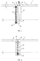
- an explosive device 1 consisting of a projectile such as a missile for example, of cylindrical shape comprising pyrotechnic materials 2 in contact or in the vicinity of which is placed in a radial position, a thermal sensor 4 produced an educated shape memory alloy to change shape by shrinking when a predetermined temperature threshold is crossed.
- the thermal sensor 4 consists of a bar, one of its ends 5 of which is secured to the body of the missile by any known means, for example a rivet, the other end 10 also being fixed in a known manner with one of the ends 9 of the rod 3 which constitutes the display element.
- the bar used is a parallelepiped having approximately the following dimensions expressed in millimeters: 150 x 8 x 1.
- the rod 3 movable in translation along its longitudinal axis, is placed in an open housing parallel to the thermal sensor.
- This rod has a sufficient length allowing its end 6 to be flush with the external surface 7 of the body of the machine before retraction of the thermal sensor.
- the sheath 8 provides better guidance of the translational movement of the rod 3 in its housing.
- a ring 13 made of elastomer for example is placed in the housing of the rod 3 at the end 6 of this rod to maintain and guide it in its movement and also seal the housing.
- Figure 2 is a variant of the previous device according to another characteristic of the invention.
- the thermal sensor 11 identical in shape to that described above, is here made of an alloy with shape memory educated to elongate when a critical temperature threshold is crossed.
- the sensor is placed in the radial position in an open housing 12 made in the pyrotechnic materials of the craft.
- One of the ends 5 of the sensor is secured to the body of the machine, the other end 6 coming flush with the external surface 7 of the body of the machine as long as the sensor retains its initial shape.
- the dimensions of the housing 12 are chosen so as not to hinder the deformation by elongation undergone by the sensor, while keeping the latter close to the pyrotechnic materials 2.
- the sealing ring 13 made of elastomer is positioned in the housing 12 at the end 6 of the sensor to maintain and guide the latter in its deformation and also seal the housing.
- the two operating modes can be used interchangeably on the same explosive device comprising in particular two thermal sensors 4 and 11, one operating above + 70 ° C. and the other below -40 ° C.
- Explosive device 1 which can be a missile for example, equipped with at least one operating safety device according to the invention and stored on the battlefield for example, is subject to a significant positive or negative variation in temperature.
- the end 5 of the sensor being fixed to the body of the machine, the retraction of the alloy causes the radial translation of the display element 3 in the direction of the arrow, by through the end 10 of the sensor fixed to the end 9 of this element.
- the display element constituted by the rod 3 is guided in its movement by the sheath 8 and the sealing ring 13.
- the senor By using a simple memory effect alloy, the sensor then retains its new shape thus obtained whatever the subsequent temperature variations and, as a result, the end 6 therefore remains protruding from the external surface of the body of the machine. .
- the projecting end 6 thus constitutes a visual means of periodic or circumstantial control of the state of the machine.
- This end also plays an active role by constituting a stop preventing, in the case of a projectile, the introduction of the latter into its launching or firing system.
- the variation of the temperature of the pyrotechnic charge 2 and of the thermal sensor 11 in shape memory alloy beyond + 70 ° C or below -40 ° C results in an elongation of it.
- the thermal sensor 11 which simultaneously plays both the role of detecting the crossing of a temperature threshold and of displaying the crossing of this threshold.
- each projectile can be equipped with two embodiments thus described, in order to ensure operating safety both for temperature variations beyond + 70 ° C and for those below -40 ° C, using two different type memory thermal sensors, specially trained for this purpose.
Landscapes
- Engineering & Computer Science (AREA)
- General Engineering & Computer Science (AREA)
- Measuring Temperature Or Quantity Of Heat (AREA)
- Testing Of Engines (AREA)
Claims (9)
- Funktionssicherheitsvorrichtung für Spreng- und/oder Antriebskörper (1), der einer Temperaturänderung ausgesetzt ist. Dieser Typ von Körper enthält pyrotechnische Materialien (2) und verfügt über mindestens ein bewegungsauslösendes Element, das auf einen Anzeiger (3) wirkt, der den Zustand des Körpers signalisiert. Ferner zeichnet dieser Typ sich dadurch aus, daß das bewegungsauslösende Element einen thermischen Fühler (4, 11) aus einer Memory-Legierung aufweist, der mit pyrotechnischen Materialien in Berührung kommt oder sich in deren Nähe befindet. Eine weitere Eigenschaft besteht darin, daß der thermische Fühler mit dem Anzeiger (3) zusammenarbeitet, sobald eine zuvor festgelegte Temperaturschwelle überschritten wurde.
- Funktionssicherheitssystem gemäß Patentanspruch 1, das sich dadurch auszeichnet, daß die Memory-Legierung, die für die Herstellung des thermischen Fühler (4,11) verwendet wird, ein einfaches Formerinnerungsvermögen aufweist. Das hat zur Folge, daß sich der Fühler negativ oder positiv verformt, sobald eine kritische Temperaturschwelle überschritten wurde, ab der die Sicherheit und die Zuverlässigkeit des Spreng- oder Antriebskörpers verringert oder nicht mehr gewährleistet sind.
- Funktionssicherheitssystem entsprechend Patentanspruch 2, welches in diesem Fall dadurch gekennzeichnet ist, daß der thermische Fühler (4, 11) von einem Steg gebildet wird, dessen eines Ende (5) mit dem Gehäuse des Körpers verbunden ist. Ein weiteres Charakteristikum besteht darin, daß die negative oder positive Verformung des Fühlers eine Bewegung des Anzeigers auslöst. Ferner steht das Ende (6) dieses Anzeigers nach der Verformung des Fühlers an der äußeren Oberfläche des Gehäuses des Körpers hervor.
- Funktionssicherheitssystem entsprechend Patentanspruch 3, das die folgenden Charakteristika aufweist: Der thermische Fühler (4, 11) ist mit den pyrotechnischen Materialien (2) direkt in Kontakt oder befindet sich in deren Nähe. Seine Anordnung erfolgt in radialer Position, wobei der Anzeiger (3) auf Grund der negativen oder positiven Verformung des Fühlers eine radiale Bewegung vollzieht.
- Funktionssicherheitssystem gemäß Patentanspruch 4, das sich dadurch auszeichnet, daß der Anzeiger von einem beweglichen Stiel (3) gebildet wird, der bei seiner Bewegung durch eine Scheide (8) in einer Lagerung geleitet wird, die eine Öffnung nach außen aufweist und parallel zum thermischen Fühler angeordnet ist. Der thermische Fühler ist so gestaltet, daß er sich bei einer zuvor festgelegten Temperaturschwelle zurückzieht und gleichzeitig die Bewegung des Stiels (8) auslöst. Der Stiel ist bei diesem Typ von Sicherheitssystem an einem seiner Enden (9) mit dem beweglichen Ende (10) des thermischen Fühlers verbunden.
- Funktionssicherheitssystem entsprechend Patentanspruch 3 oder 4. Für diesem Fall ist charakteristisch, daß der Anzeiger von einem thermischen Fühler (11) gebildet wird, der in einer Lagerung (12) liegt, die eine Öffnung nach außen aufweist. Darüber hinaus ist der thermische Fühler innerhalb der pyrotechnischen Materialien (2) plaziert, und das Überschreiten einer zuvor bestimmten Temperaturschwelle führt zu einer Längsausdehnung des Fühlers.
- Funktionssicherheitssystem gemäß eines beliebigen der unter 1 bis 6 formulierten Patentanspriiche. Diese Konstellation zeichnet sich dadurch aus, daß der Anzeiger (3, 11) durch einen Dichtungsring (13) aus Elastomer in einer Lagerung gehalten und bei seiner Bewegung geführt wird.
- Funktionssicherheitssystem entsprechend eines beliebigen der unter 1 bis 7 beschriebenen Patentansprüche, wobei die Besonderheit in diesem Fall darin besteht, daß die Temperaturschwellen bei ungefähr +70°C oder -40°C liegen.
- Funktionssicherheitssystem gemäß eines beliebigen der unter 1 bis 8 formulierten Patentansprüche, das dadurch gekennzeichnet ist, daß es zwei thermische Fühler (4, 11) umfaßt. Der erste (4) der beiden Fühler löst die Bewegung des Anzeigers bei Temperaturen von über +70°C aus; der zweite (11) der beiden Fühler reagiert auf Temperaturen von unter -40°C.
Applications Claiming Priority (2)
| Application Number | Priority Date | Filing Date | Title |
|---|---|---|---|
| FR9113443 | 1991-10-31 | ||
| FR9113443A FR2683312B1 (fr) | 1991-10-31 | 1991-10-31 | Dispositif de securite de fonctionnement pour engin explosif et/ou propulsif soumis a une variation de temperature. |
Publications (2)
| Publication Number | Publication Date |
|---|---|
| EP0540418A1 EP0540418A1 (de) | 1993-05-05 |
| EP0540418B1 true EP0540418B1 (de) | 1995-05-17 |
Family
ID=9418492
Family Applications (1)
| Application Number | Title | Priority Date | Filing Date |
|---|---|---|---|
| EP19920402933 Expired - Lifetime EP0540418B1 (de) | 1991-10-31 | 1992-10-29 | Sicherheitsvorrichtung für Spreng- oder Treibladungen die Temperaturschwankungen ausgesetzt sind |
Country Status (4)
| Country | Link |
|---|---|
| EP (1) | EP0540418B1 (de) |
| DE (1) | DE69202546T2 (de) |
| ES (1) | ES2074849T3 (de) |
| FR (1) | FR2683312B1 (de) |
Families Citing this family (1)
| Publication number | Priority date | Publication date | Assignee | Title |
|---|---|---|---|---|
| SE519561C2 (sv) * | 2000-07-03 | 2003-03-11 | Bofors Carl Gustaf Ab | Anordning vid raketmotorer för att förhindra att raketmotor bringas att explodera vid utvändig brand |
Family Cites Families (3)
| Publication number | Priority date | Publication date | Assignee | Title |
|---|---|---|---|---|
| FR2563001B1 (fr) * | 1984-04-16 | 1987-09-25 | France Etat Armement | Dispositif de neutralisation et de visualisation de la neutralisation d'un systeme d'amorcage |
| US5035181A (en) * | 1985-01-22 | 1991-07-30 | The United States Of America As Represented By The Secretary Of The Navy | Thermosensitive pop-out device |
| FR2650670A1 (fr) * | 1989-08-02 | 1991-02-08 | Fiori Costantino | Systeme de detection d'incendie ou de tout autre phenomene engendrant une elevation ou une baisse anormale de temperature par rapport a une reference fixee |
-
1991
- 1991-10-31 FR FR9113443A patent/FR2683312B1/fr not_active Expired - Fee Related
-
1992
- 1992-10-29 EP EP19920402933 patent/EP0540418B1/de not_active Expired - Lifetime
- 1992-10-29 ES ES92402933T patent/ES2074849T3/es not_active Expired - Lifetime
- 1992-10-29 DE DE1992602546 patent/DE69202546T2/de not_active Expired - Fee Related
Also Published As
| Publication number | Publication date |
|---|---|
| DE69202546T2 (de) | 1996-02-29 |
| DE69202546D1 (de) | 1995-06-22 |
| EP0540418A1 (de) | 1993-05-05 |
| FR2683312A1 (fr) | 1993-05-07 |
| ES2074849T3 (es) | 1995-09-16 |
| FR2683312B1 (fr) | 1994-01-28 |
Similar Documents
| Publication | Publication Date | Title |
|---|---|---|
| EP0434505B1 (de) | Peripheriemantel für einen rohrabgeschossenen gelenkten Flugkörper | |
| EP0389358B1 (de) | Leitwerkausspreizungssystem für ein Geschoss | |
| FR2615609A1 (fr) | Dispositif d'amorcage photopyrotechnique et chaine photopyrotechnique utilisant ce dispositif | |
| EP0694753B1 (de) | Pyrotechnische Vorrichtung zum Abschuss von mindestens einem Geschoss | |
| WO1993013382A1 (fr) | Tube douille pour grenade a fusil pouvant retenir les fragments de la balle | |
| EP0540418A1 (de) | Sicherheitsvorrichtung für Spreng- oder Treibladungen die Temperaturschwankungen ausgesetzt sind | |
| EP0267090B1 (de) | Gewehrgranate | |
| WO1995002162A1 (fr) | Dispositif pour l'entretien de la surface interne de canons d'armes et procede de fabrication du dispositif | |
| WO2011141527A1 (fr) | Munition guidee protegee par une coiffe aerodynamique | |
| EP1500902B1 (de) | Selbst-Zerlegerzünder für drallstabilisierte Geschosse | |
| EP0030051A1 (de) | Gewehrgranate | |
| EP0316216B1 (de) | Einrichtung zur Kreiselstabilisierung eines Geschoss-Steuerorgans | |
| FR2672673A1 (fr) | Dispositif d'amorcage pour un sous-projectile. | |
| CA1334908C (fr) | Dispositif d'ouverture d'empennage pour obus | |
| EP0779495A1 (de) | Abschussvorrichtung für ein nichtletales Geschoss | |
| EP0463974B1 (de) | Einrichtung zum Sichern und zum Schärfen einer Munition | |
| FR2512195A1 (fr) | Dispositif de securite et d'armement pour l'amorcage de charges sous-marines | |
| BE1005559A3 (fr) | Dispositif de securite, respectivement retardateur, pour projectile. | |
| EP0559520B1 (de) | Barometrisches Sicherheitsventil und einer eine ähnliche pyrotechnische Vorrichtung enthaltender Gegenstand | |
| EP0207822B1 (de) | Sicherheitsvorrichtung für von Rohren abgeschossenen explosiven Flugkörper | |
| BE1001908A3 (fr) | Projectile pour le tir a portee reduite. | |
| EP0809085B1 (de) | Sicherheits- und Spannvorrichtung, insbesondere für Minen | |
| EP2461129A1 (de) | Vorrichtung zum Verhärten einer mechanischen Verbindung eines Antriebs für Kanonenmunition, und mit einer solchen Verbindung ausgestattete Munition | |
| WO2023187048A1 (fr) | Dispositif de sécurité pour un réservoir destiné à contenir un gaz sous pression | |
| FR2660748A1 (fr) | Projectile empenne a indicateur de tir (cas 1). |
Legal Events
| Date | Code | Title | Description |
|---|---|---|---|
| PUAI | Public reference made under article 153(3) epc to a published international application that has entered the european phase |
Free format text: ORIGINAL CODE: 0009012 |
|
| 17P | Request for examination filed |
Effective date: 19921120 |
|
| AK | Designated contracting states |
Kind code of ref document: A1 Designated state(s): DE ES GB IT SE |
|
| 17Q | First examination report despatched |
Effective date: 19941102 |
|
| GRAA | (expected) grant |
Free format text: ORIGINAL CODE: 0009210 |
|
| AK | Designated contracting states |
Kind code of ref document: B1 Designated state(s): DE ES GB IT SE |
|
| REF | Corresponds to: |
Ref document number: 69202546 Country of ref document: DE Date of ref document: 19950622 |
|
| ITF | It: translation for a ep patent filed | ||
| REG | Reference to a national code |
Ref country code: ES Ref legal event code: FG2A Ref document number: 2074849 Country of ref document: ES Kind code of ref document: T3 |
|
| GBT | Gb: translation of ep patent filed (gb section 77(6)(a)/1977) |
Effective date: 19950825 |
|
| PLBE | No opposition filed within time limit |
Free format text: ORIGINAL CODE: 0009261 |
|
| STAA | Information on the status of an ep patent application or granted ep patent |
Free format text: STATUS: NO OPPOSITION FILED WITHIN TIME LIMIT |
|
| 26N | No opposition filed | ||
| REG | Reference to a national code |
Ref country code: GB Ref legal event code: IF02 |
|
| PGFP | Annual fee paid to national office [announced via postgrant information from national office to epo] |
Ref country code: ES Payment date: 20021008 Year of fee payment: 11 |
|
| PGFP | Annual fee paid to national office [announced via postgrant information from national office to epo] |
Ref country code: SE Payment date: 20021009 Year of fee payment: 11 |
|
| PGFP | Annual fee paid to national office [announced via postgrant information from national office to epo] |
Ref country code: DE Payment date: 20021218 Year of fee payment: 11 |
|
| PGFP | Annual fee paid to national office [announced via postgrant information from national office to epo] |
Ref country code: GB Payment date: 20030730 Year of fee payment: 12 |
|
| PG25 | Lapsed in a contracting state [announced via postgrant information from national office to epo] |
Ref country code: SE Free format text: LAPSE BECAUSE OF NON-PAYMENT OF DUE FEES Effective date: 20031030 Ref country code: ES Free format text: LAPSE BECAUSE OF NON-PAYMENT OF DUE FEES Effective date: 20031030 |
|
| PG25 | Lapsed in a contracting state [announced via postgrant information from national office to epo] |
Ref country code: DE Free format text: LAPSE BECAUSE OF NON-PAYMENT OF DUE FEES Effective date: 20040501 |
|
| EUG | Se: european patent has lapsed | ||
| PG25 | Lapsed in a contracting state [announced via postgrant information from national office to epo] |
Ref country code: GB Free format text: LAPSE BECAUSE OF NON-PAYMENT OF DUE FEES Effective date: 20041029 |
|
| REG | Reference to a national code |
Ref country code: ES Ref legal event code: FD2A Effective date: 20031030 |
|
| GBPC | Gb: european patent ceased through non-payment of renewal fee |
Effective date: 20041029 |
|
| PG25 | Lapsed in a contracting state [announced via postgrant information from national office to epo] |
Ref country code: IT Free format text: LAPSE BECAUSE OF NON-PAYMENT OF DUE FEES;WARNING: LAPSES OF ITALIAN PATENTS WITH EFFECTIVE DATE BEFORE 2007 MAY HAVE OCCURRED AT ANY TIME BEFORE 2007. THE CORRECT EFFECTIVE DATE MAY BE DIFFERENT FROM THE ONE RECORDED. Effective date: 20051029 |