EP0539792B1 - Method for regenerating etchant - Google Patents
Method for regenerating etchant Download PDFInfo
- Publication number
- EP0539792B1 EP0539792B1 EP92117448A EP92117448A EP0539792B1 EP 0539792 B1 EP0539792 B1 EP 0539792B1 EP 92117448 A EP92117448 A EP 92117448A EP 92117448 A EP92117448 A EP 92117448A EP 0539792 B1 EP0539792 B1 EP 0539792B1
- Authority
- EP
- European Patent Office
- Prior art keywords
- copper
- etchant
- chloride
- waste
- chlorine gas
- Prior art date
- Legal status (The legal status is an assumption and is not a legal conclusion. Google has not performed a legal analysis and makes no representation as to the accuracy of the status listed.)
- Expired - Lifetime
Links
Images
Classifications
-
- C—CHEMISTRY; METALLURGY
- C23—COATING METALLIC MATERIAL; COATING MATERIAL WITH METALLIC MATERIAL; CHEMICAL SURFACE TREATMENT; DIFFUSION TREATMENT OF METALLIC MATERIAL; COATING BY VACUUM EVAPORATION, BY SPUTTERING, BY ION IMPLANTATION OR BY CHEMICAL VAPOUR DEPOSITION, IN GENERAL; INHIBITING CORROSION OF METALLIC MATERIAL OR INCRUSTATION IN GENERAL
- C23F—NON-MECHANICAL REMOVAL OF METALLIC MATERIAL FROM SURFACE; INHIBITING CORROSION OF METALLIC MATERIAL OR INCRUSTATION IN GENERAL; MULTI-STEP PROCESSES FOR SURFACE TREATMENT OF METALLIC MATERIAL INVOLVING AT LEAST ONE PROCESS PROVIDED FOR IN CLASS C23 AND AT LEAST ONE PROCESS COVERED BY SUBCLASS C21D OR C22F OR CLASS C25
- C23F1/00—Etching metallic material by chemical means
- C23F1/46—Regeneration of etching compositions
-
- C—CHEMISTRY; METALLURGY
- C25—ELECTROLYTIC OR ELECTROPHORETIC PROCESSES; APPARATUS THEREFOR
- C25F—PROCESSES FOR THE ELECTROLYTIC REMOVAL OF MATERIALS FROM OBJECTS; APPARATUS THEREFOR
- C25F7/00—Constructional parts, or assemblies thereof, of cells for electrolytic removal of material from objects; Servicing or operating
- C25F7/02—Regeneration of process liquids
Definitions
- This invention relates to a method for treating an etchant, more specifically a method for treating an etchant including copper (II) chloride.
- a conductive pattern of e.g., an integrated circuit in a substrate is manufactured by solving copper in areas other than those corresponding to conducting lines to be used with the aid of a solution of copper (II) chloride.
- CuCl in the waste is regenerated into copper (II) chloride CuCl 2 with the aid of hydrochloric acid and hydrogen peroxide.
- an excess amount of etchant is usually supplied to a disposal tank in a factory of etching and, therefore, there is a danger of pollution which eventually occurs in the course of disposal process of the excess etchant or its transportation.
- an electrolytic process is particularly well known, in which the etchant waste is decomposited in an electrolytic bath having a diaphragm between the anode and cathode cells, so that metallic copper can be obtained from copper ions deposited onto the cathode, and at the same time the ferric chloride can be regenerated by oxidition at the side of the anode.
- the etching solution after the dissolution of copper plates or copper foils in a printed circuit board contains trivalent iron ions, divalent iron ions, divalent copper ions and monovalent copper ions which result from ferric chloride and copper foils.
- the reactions of electrolytic reduction occur at the cathode of the electrolytic bath in the following sequence: Fe 3+ + e - ⁇ Fe 2+ , and then, Cu 2+ + 2e - ⁇ Cu + + e - ⁇ Cu.
- ferric chloride is first reduced to ferrous chloride in the solution, and then copper (II) chloride is reduced to copper (I) chloride, thereafter a copper metal being deposited.
- the electrolysis is continuously performed with a closely circulated apparatus for withdrawing, and at the same time if a part of copper metal deposited onto the cathode, in particular powder of metallic copper fallen out of the surface of the cathode into the solution remains at the bottom, FeCl 3 or CuCl 2 which is newly supplied into the etchant reacts as follows: FeCl 3 + Cu ⁇ FeCl 2 + CuCl CuCl 2 + Cu ⁇ 2CuCl Accordingly, the copper which has once been deposited is again dissolved into the solution, thereby reducing the efficiency of copper recovery. In addition, the dissolution provides a considerable amount of CuCl in the regenerated solution. These eventually result in a decreased efficiency of etching.
- the Japanese Patent Laid Open Sho 55-18558 has disclosed a method for continuously withdrawing copper by electrolysis from the etchant waste including ferric chloride containing copper and for regenerating the etchant of ferric chloride, in which case the electrolytic reduction process is divided into two steps: In the first step, ferric chloride and copper (II) chloride are reduced to ferrous and copper chlorides, respectively, and, in the second step, metallic copper is deposited.
- the object of this invention is to offer a method for treating an etchant in a one stage of electrolytic process, in order to avoid various troubles which are said to be, in case of closed system, occured as well as the drawbacks in the above-mentioned methods in the prior art, thereby ensuring an easy operation, a decreased cost in maintenance and installation, and a safety and effective use of chlorine gas generated in the system.
- Another object of this invention is to regenerate an etching waste with a high efficiency as well as to withdraw copper having a purity of more than 90 % from the waste by employing both the electrolysis with a diaphragm cell and the oxidation with chlorine gas.
- Another object of this invention is to provide an ease and reliable adjustment in supplying the etchant waste into only the cathode cell of an electrolytic bath, on the contrary to the prior method in which the etchant waste is supplied to both cathode and anode cells.
- the fundamental concept of this invention is that the etchant waste is treated by means of both the electrolysis with a diaphragm cell and the oxidation with chlorine gas. Especially, all the chlorine gas generated in the anode cell is used, so that the etchant can be regenerated without loss.
- the method of oxidation with chlorine gas has been regarded merely as an unverified method of regeneration, as pointed out in the Japanese Patent Laid Open Hei 2-254188.
- the present inventors succeeded in confirming its utilizability as well as in overcoming "the problems on the environmental hygiene" by employing a closed electrolytic bath accompanied with an absorbing tower, the electrolytic bath being developed for realizing the present method.
- the process for regenerating the etchant consists of a first step at which the etchant including copper (I) chloride is supplied to the cathode cell of an electrolyzer for withdrawing metallic copper, a second step at which the etchant after the removal of copper is then conducted to the anode cell in order to oxidize monovalent copper ions contained into divalent copper ions, together with the generation of chlorine gas, a third step at which the chlorine gas thus generated is supplied to an absorbing tower, and a fourth step of introducing in said absorbing tower another waste copper (II) chloride etchant including copper (I) chloride used in an etching process, thereby enabling the etchant to be oxidized and to be regenerated.
- the process consists of a first step at which the etchant is supplied to the cathode cell of an electrolyzer for withdrawing metallic copper, a second step at which the etchant after the removal of copper is further supplied to another etchant to form a mixture solution, and a third step at which the chlorine gas generated at the first step is supplied to the mixture solution to oxidize it.
- the electrolytic diaphragm used in the present invention is needed to possess the following properties; 1 the restricted mobility of complex salts of copper chlorine in the cathode cell towards the anode cell and the isolation between the solutions in the anode and cathode so as to prevent mixture of them even for a certain amount of vibration in the surface of the solution, 2 as small electrical resistivity as possible, 3 agent-proof, in particular against chlorinating, and 4 no polarity in the diaphragm itself, i.e., electrically neutral and no dipole therein.
- a diaphragm can be prepared from modoacryl (trade name), vinyl acetate, polyester, vinylidene chloride, or the like.
- the anode in the electrolytic bath is needed to possess a function of decreasing the overvoltage in the generation of chlorine gas.
- it can be prepared from platinum or a dimensional stable anode (denoted by DSA), such as (Ru-Sn)O 2 /Ti, (Ir-Pt)O 2 /Ti.
- DSA dimensional stable anode
- titan can preferably be used as a cathode.
- the etchant generated in the etching bath i.e., the etching solution including copper (I) chloride and unreacted copper (II) chloride is initially transported to the cathode cell in the electrolyzer. And then, inside the cathode cell in which a circulated cathode solution comes in and out, trivalent iron ions are reduced into divalent iron ions, after that excess divalent copper ions and monovalent copper ions are reduced and deposited on the electrode, thus enabling metallic copper to be withdrawn.
- the etchant generated in the etching bath i.e., the etching solution including copper (I) chloride and unreacted copper (II) chloride is initially transported to the cathode cell in the electrolyzer. And then, inside the cathode cell in which a circulated cathode solution comes in and out, trivalent iron ions are reduced into divalent iron ions, after that excess divalent copper ions and monovalent copper ions are reduced and deposited on the electrode, thus
- the solution leaving the cathode cell with a decreased copper concentration is now apart from the circulating system, and then conducted to the anode cell, where chlorine ions lose their own electrons so that chlorine gas generates.
- the chlorine gas is supplied to an absorbing tower.
- the solution which has a decreased concentration of chlorine due to the generation of chlorine gas and at the same time monovalent copper ions are electrolytically oxidized into divalent copper ions, is apart from the circulating system at the anode, and then returns to the etching bath as a regenerated etchant.
- the etchant generated in the etching bath i.e., the etchant including copper (I) chloride and unreacted copper (II) chloride is supplied to not only the electrolyzer, but also to the absorbing tower. With the aid of the chlorine gas which generates at the electrolyzer and then is supplied to the absorbing tower, the etchant including copper (I) chloride and unreacted copper (II) chloride is oxidized for the regeneration according to the equation of reaction, 2CuCl + Cl 2 ⁇ 2CuCl 2 .
- the copper (II) chloride thus regenerated is returned as a regenerated etchant to the etching bath.
- the solution which is reduced at a decreased copper concentration in the cathode cell and then leaves the cell can also be supplied directly to the etchant conducted to the absorbing tower.
- chlorine ions and copper chlorine complexes which travel towards the anode, passing through the diaphragm in the electrolytic bath, are oxidized, hence generating the chlorine gas.
- the etchant thus mixed is regenerated by introducing the chlorine gas into the absorbing tower, and thus returned as a regenerated etchant to the etching bath.
- the generation of chlorine gas is usually designed to be as small as possible. It must be noted, however, that in the present invention the chlorine gas is positively used in order to regenerate the etchant in a completely closed system.
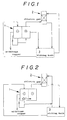
- Fig. 1 is a conceptual flow chart in the first embodiment of this invention.
- Fig. 2 is a conceptual flow chart in another embodiment of this invention.
- an etchant including a copper content of 121 g/l (8.6 g/l for monovalent copper ions) and a chlorine content of 300 g/l was supplied at a flow rate of 9.6 ml/min to a cathode cell (electrode; Cu) in electrolyzer 1 having a modoacryl diaphragm, where the bath was operated at an electrolytic voltage of 2.1 DC V.
- a cathode cell where a circulated cathode solution came in and went out, excess monovalent and divalent copper ions were electrolytically deposited after taking place reduction.
- the chemical analysis showed that the deposited metal had a copper content of 93.9 %.
- the production rate of withdrawn copper was 51.7 g/h and the power necessary for the electrolysis per 1 g copper was 2.03 Wh/g.
- the solution extracted from the circulation system had a copper content of 30.8 g/l (0.0 g/l for monovalent copper ions) and a chlorine content of 185 g/l, and was returned as a regenerated etchant to etching bath 3.
- the etching solution generated in etching bath 3 had a copper content of 121 g/l (8.6 g/l for monovalent copper ions) and a chlorine content of 300 g/l.
- the etchant was supplied not only to the electrolyzer 1 having the diaphragm, but also to the absorbing tower at a flow rate of 200 ml/min.
- the etchant was oxidized by the chlorine gas which initially generated at electrolyzer 1 and then supplied to absorbing tower 2.
- the resultant solution had a copper content of 121 g/l (0.0 g/l for monovalent copper ions) and a chlorine content of 304 g/l. Therefore, it was confirmed that the solution obtained was generated as a solution including copper (II) chloride. This solution was returned as a regenerated etchant to etching bath 3.
- an etchant including a copper content of 121 g/l (8.9 g/l for monovalent copper ions) and a chlorine content of 302 g/l was first supplied at a flow rate of 8.33 ml/min to a cathode cell (electrode; Cu) in electrolyzer 1 having a modoacryl diaphragm, where the bath was operated at an electrolytic voltage of 2.0 DC V.
- a cathode cell where a circulated cathode solution came in and went out, excess monovalent and divalent copper ions were electrolytically deposited after taking place reduction.
- the chemical analysis showed that the deposited metal had copper content of 97.5 %.
- the production rate of withdrawn copper was 45.1 g/h and the power necessary for the electrolysis per 1 gr copper was 2.3 Wh/g.
- the solution which left the cathode cell in a decreased concentration of copper was mixed to another etchant including a copper content of 121 g/l (14.2 g/l for monovalent copper ions) and a chlorine content of 302 g/l, this etchant being generated in etching bath 3.
- the mixed solution including a copper content of 117 g/l (14.5 g/l for monovalent copper ions) and a chlorine content of 297 g/l was supplied at a flow rate of 100 ml/min to absorbing tower 2.
- anode cell electrolyzer I having the diaphragm
- chlorine ions which generated in the cathode cell and flowed in the anode cell through the diaphragm was oxidized, thus generating chlorine gas at a rate of 59.7 g/h.
- the chlorine gas generated was introduced into absorbing tower 2.
- the mixed solution was oxidized by the chlorine gas.
- the resultant solution had a copper content of 117 g/l (0.0 g/l for monovalent copper ions) and a chlorine content of 304 g/l. It was confirmed that the solution obtained was generated as a solution including copper (II) chloride. This solution was returned as a regenerated etchant to etching bath 3.
Landscapes
- Chemical & Material Sciences (AREA)
- Chemical Kinetics & Catalysis (AREA)
- Engineering & Computer Science (AREA)
- Materials Engineering (AREA)
- Metallurgy (AREA)
- Organic Chemistry (AREA)
- General Chemical & Material Sciences (AREA)
- Mechanical Engineering (AREA)
- Electrochemistry (AREA)
- ing And Chemical Polishing (AREA)
- Electrolytic Production Of Metals (AREA)
Description
- This invention relates to a method for treating an etchant, more specifically a method for treating an etchant including copper (II) chloride.
- It is generally known that a conductive pattern of e.g., an integrated circuit in a substrate is manufactured by solving copper in areas other than those corresponding to conducting lines to be used with the aid of a solution of copper (II) chloride.
- It is desirable to regenerate the waste of etchant and thus to reuse it for other etching processes from the view point of avoiding the environmental pollution and economic requirements, where the etchant waste contains copper (I) chloride produced in the following etching process:

- In one of the most typical methods for regenerating the waste of etchant containing copper (I) chloride, CuCl in the waste is regenerated into copper (II) chloride CuCl2 with the aid of hydrochloric acid and hydrogen peroxide.
- In this method, however, all contents of copper dissolved from the copper foil of the substrate into the etching solution are stored as copper (II) chloride CuCl2, thereby rapidly giving rise to an excess concentration of CuCl2.
- Accordingly, an excess amount of etchant is usually supplied to a disposal tank in a factory of etching and, therefore, there is a danger of pollution which eventually occurs in the course of disposal process of the excess etchant or its transportation.
- In spite of the above-mentioned treatment with hydrogen peroxide, an improvement for etching has been proposed where the etchant waste is electrolytically treated, so that the etchant is regenerated by changing copper (I) chloride CuCl into copper (II) chloride CuCl2 with the aid of chlorine generated at the side of the anode in which the waste is transported, and at the same time copper can be electrolytically withdrawn from deposited copper ions as metallic copper at the side of the cathode in which the waste is similarly transported. This method has been disclosed in the Japanese Patent Publication Sho 56-17429, and has already been applied to practical uses.
- In this patent publication, the proper adjustment of liquid phase composition in the cathode cell of an electrolytic bath is particularly recommended.
- In the method for withdrawing copper on the basis of the electrolytic process according to the Japanese Patent Publication Sho 56-17429, however, complicated operations are required for controlling the liquid phase composition, the respective flow rates of solution supplied to the cathode and anode cells, the balance in pressure, etc, because the liquid phase composition must be kept at a reduced copper concentration of less than 65 g/l for the composite solution of both copper (I) and copper (II) chlorides, under the conditions that the etchant waste is separately supplied into the cathode and anode cells. Moreover, no explicit description is given on the method for treating chlorine gas to be generated; without the treatment, a danger of deteriorating the working environment increases due to the generated chlorine gas.
- Moreover, as for the etchant waste resulting from the etching process with a solution of ferric chloride, an electrolytic process is particularly well known, in which the etchant waste is decomposited in an electrolytic bath having a diaphragm between the anode and cathode cells, so that metallic copper can be obtained from copper ions deposited onto the cathode, and at the same time the ferric chloride can be regenerated by oxidition at the side of the anode.
- In such an electrolytic process, the etching solution after the dissolution of copper plates or copper foils in a printed circuit board contains trivalent iron ions, divalent iron ions, divalent copper ions and monovalent copper ions which result from ferric chloride and copper foils. In the course of electrolysis for such an etchant, the reactions of electrolytic reduction occur at the cathode of the electrolytic bath in the following sequence:


- In other words, ferric chloride is first reduced to ferrous chloride in the solution, and then copper (II) chloride is reduced to copper (I) chloride, thereafter a copper metal being deposited. If, therefore, the electrolysis is continuously performed with a closely circulated apparatus for withdrawing, and at the same time if a part of copper metal deposited onto the cathode, in particular powder of metallic copper fallen out of the surface of the cathode into the solution remains at the bottom, FeCl3 or CuCl2 which is newly supplied into the etchant reacts as follows:


- Taking into account these facts, the Japanese Patent Laid Open Sho 55-18558 has disclosed a method for continuously withdrawing copper by electrolysis from the etchant waste including ferric chloride containing copper and for regenerating the etchant of ferric chloride, in which case the electrolytic reduction process is divided into two steps: In the first step, ferric chloride and copper (II) chloride are reduced to ferrous and copper chlorides, respectively, and, in the second step, metallic copper is deposited.
- In the method for withdrawing copper on the basis of the electrolysis according to the above-mentioned patent publication, however, there are drawbacks due to the complicated installation which permits the reduction of the etchant to be performed just before the electrolytic deposition of copper occurs in the first step, and also due to the difficulty in controlling the liquid phase composition. In addition, alike the Japanese Patent Publication Sho 56-17429, the method for treating the chlorine gas to be generated is not described. Therefore, there is a danger of deteriorating the working environment due to the resultant gas of chlorine.
- In the publication "GALVANOTECHNIK, Volume 75, Number 5, Pages 678-679, May 1984, Saulgau, DE, K.-E. Knipps: Verfahren zur Regeneration von Kupferchlorid-Atzlösungen" a process for regeneration of copper chloride etchants is known, which regeneration process is divided into separated systems, namely the system of the etching machine and the system of the electrolysis circuit. Both systems are only connected by the generation of chlorine by electrolysis and supplying the chlorine into the circuit of the etching machine. However, there is no interconnection in the system concerning the etchant circuit.
- The publication "SOVIET INVENTIONS ILLUSTRATED, Section Ch, Week 8413, 9 May 1984, Derwent Publications Ltd., London, GB; AN 84-080088/13 & SU-A-1019681 (NIKULIK B. A.)" discloses an etching apparatus, which includes a bath with two sections, one of which is communicating with the etching chamber and the other with an electrolyzer and ejector. This apparatus provides continuous regeneration of the etching solution.
- Incidentally, if one is restricted only on withdrawing metallic copper from the etchant waste, it is possible to use so called cementation in which iron powder is put into the waste, thereby enabling copper to be reduced on account of the difference in ionization tendency. However, the cementation provides an excess content of iron in the solution treated, the reuse of the etchant is impossible and the used etchant is abandoned. As a result, this method cannot assure the avoidance of pollution in the environment, nor the requirement for the economy.
- Accordingly, the object of this invention is to offer a method for treating an etchant in a one stage of electrolytic process, in order to avoid various troubles which are said to be, in case of closed system, occured as well as the drawbacks in the above-mentioned methods in the prior art, thereby ensuring an easy operation, a decreased cost in maintenance and installation, and a safety and effective use of chlorine gas generated in the system.
- Another object of this invention is to regenerate an etching waste with a high efficiency as well as to withdraw copper having a purity of more than 90 % from the waste by employing both the electrolysis with a diaphragm cell and the oxidation with chlorine gas.
- Another object of this invention is to provide an ease and reliable adjustment in supplying the etchant waste into only the cathode cell of an electrolytic bath, on the contrary to the prior method in which the etchant waste is supplied to both cathode and anode cells.
- In accordance with this invention, the objects are attained by a method according to
claim - The fundamental concept of this invention is that the etchant waste is treated by means of both the electrolysis with a diaphragm cell and the oxidation with chlorine gas. Especially, all the chlorine gas generated in the anode cell is used, so that the etchant can be regenerated without loss.
- The method of oxidation with chlorine gas has been regarded merely as an unverified method of regeneration, as pointed out in the Japanese Patent Laid Open Hei 2-254188. However, the present inventors succeeded in confirming its utilizability as well as in overcoming "the problems on the environmental hygiene" by employing a closed electrolytic bath accompanied with an absorbing tower, the electrolytic bath being developed for realizing the present method.
- The process according to the present invention is now described in detail:
- It is advantageous that the process for regenerating the etchant consists of a first step at which the etchant including copper (I) chloride is supplied to the cathode cell of an electrolyzer for withdrawing metallic copper, a second step at which the etchant after the removal of copper is then conducted to the anode cell in order to oxidize monovalent copper ions contained into divalent copper ions, together with the generation of chlorine gas, a third step at which the chlorine gas thus generated is supplied to an absorbing tower, and a fourth step of introducing in said absorbing tower another waste copper (II) chloride etchant including copper (I) chloride used in an etching process, thereby enabling the etchant to be oxidized and to be regenerated.
- As another embodiment according to
claim 2, it is also advantageous that the process consists of a first step at which the etchant is supplied to the cathode cell of an electrolyzer for withdrawing metallic copper, a second step at which the etchant after the removal of copper is further supplied to another etchant to form a mixture solution, and a third step at which the chlorine gas generated at the first step is supplied to the mixture solution to oxidize it. - The electrolytic diaphragm used in the present invention is needed to possess the following properties; ① the restricted mobility of complex salts of copper chlorine in the cathode cell towards the anode cell and the isolation between the solutions in the anode and cathode so as to prevent mixture of them even for a certain amount of vibration in the surface of the solution, ② as small electrical resistivity as possible, ③ agent-proof, in particular against chlorinating, and ④ no polarity in the diaphragm itself, i.e., electrically neutral and no dipole therein. Such a diaphragm can be prepared from modoacryl (trade name), vinyl acetate, polyester, vinylidene chloride, or the like.
- The anode in the electrolytic bath is needed to possess a function of decreasing the overvoltage in the generation of chlorine gas. Advantageously, it can be prepared from platinum or a dimensional stable anode (denoted by DSA), such as (Ru-Sn)O2/Ti, (Ir-Pt)O2/Ti. As a cathode, titan can preferably be used. The utilization of the electrodes thus specified provides copper crystals which are unresolvable into the solution and which easily exfoliates from the surface of the electrode.
- In accordance with the present invention, the etchant generated in the etching bath, i.e., the etching solution including copper (I) chloride and unreacted copper (II) chloride is initially transported to the cathode cell in the electrolyzer. And then, inside the cathode cell in which a circulated cathode solution comes in and out, trivalent iron ions are reduced into divalent iron ions, after that excess divalent copper ions and monovalent copper ions are reduced and deposited on the electrode, thus enabling metallic copper to be withdrawn.
- The solution leaving the cathode cell with a decreased copper concentration is now apart from the circulating system, and then conducted to the anode cell, where chlorine ions lose their own electrons so that chlorine gas generates. The chlorine gas is supplied to an absorbing tower. The solution, which has a decreased concentration of chlorine due to the generation of chlorine gas and at the same time monovalent copper ions are electrolytically oxidized into divalent copper ions, is apart from the circulating system at the anode, and then returns to the etching bath as a regenerated etchant.
- The etchant generated in the etching bath, i.e., the etchant including copper (I) chloride and unreacted copper (II) chloride is supplied to not only the electrolyzer, but also to the absorbing tower. With the aid of the chlorine gas which generates at the electrolyzer and then is supplied to the absorbing tower, the etchant including copper (I) chloride and unreacted copper (II) chloride is oxidized for the regeneration according to the equation of reaction,

- The copper (II) chloride thus regenerated is returned as a regenerated etchant to the etching bath.
- The solution which is reduced at a decreased copper concentration in the cathode cell and then leaves the cell, can also be supplied directly to the etchant conducted to the absorbing tower. In this case, chlorine ions and copper chlorine complexes, which travel towards the anode, passing through the diaphragm in the electrolytic bath, are oxidized, hence generating the chlorine gas. The etchant thus mixed is regenerated by introducing the chlorine gas into the absorbing tower, and thus returned as a regenerated etchant to the etching bath.
- In the conventional electrolytic method, the generation of chlorine gas is usually designed to be as small as possible. It must be noted, however, that in the present invention the chlorine gas is positively used in order to regenerate the etchant in a completely closed system.
- Furthermore, it must be mentioned that the conversion of copper (I) chloride into copper (II) chloride is often needed and the treating method according to the invention is particularly useful in various fields of the technology, aside from the application field of the circuit boards, since it provides no problems in the environmental pollution.
- Fig. 1 is a conceptual flow chart in the first embodiment of this invention.
- Fig. 2 is a conceptual flow chart in another embodiment of this invention.
- This invention will further be described below with the aid of the embodiments.
- In an apparatus which is conceptually illustrated in Fig. 1, an etchant including a copper content of 121 g/l (8.6 g/l for monovalent copper ions) and a chlorine content of 300 g/l was supplied at a flow rate of 9.6 ml/min to a cathode cell (electrode; Cu) in
electrolyzer 1 having a modoacryl diaphragm, where the bath was operated at an electrolytic voltage of 2.1 DC V. In the cathode cell where a circulated cathode solution came in and went out, excess monovalent and divalent copper ions were electrolytically deposited after taking place reduction. The chemical analysis showed that the deposited metal had a copper content of 93.9 %. The production rate of withdrawn copper was 51.7 g/h and the power necessary for the electrolysis per 1 g copper was 2.03 Wh/g. - The solution which left the cathode cell in a decreased concentration of copper was transferred from the circulation system to an anode cell (electrode; (Ru-Sn)O2/Ti). In the anode cell, chlorine ions lost their own electron, so that chlorine gas generated at a rate of 66.2 g/h. The gas was supplied to absorbing
tower 2. The solution in the circulating system at the anode decreased the concentration of chlorine due to the generation of chlorine gas, thereby being electrolytically oxidized in such a way that monovalent copper ions changed to divalent copper ions. The solution extracted from the circulation system had a copper content of 30.8 g/l (0.0 g/l for monovalent copper ions) and a chlorine content of 185 g/l, and was returned as a regenerated etchant toetching bath 3. - The etching solution generated in
etching bath 3 had a copper content of 121 g/l (8.6 g/l for monovalent copper ions) and a chlorine content of 300 g/l. The etchant was supplied not only to theelectrolyzer 1 having the diaphragm, but also to the absorbing tower at a flow rate of 200 ml/min. The etchant was oxidized by the chlorine gas which initially generated atelectrolyzer 1 and then supplied to absorbingtower 2. The resultant solution had a copper content of 121 g/l (0.0 g/l for monovalent copper ions) and a chlorine content of 304 g/l. Therefore, it was confirmed that the solution obtained was generated as a solution including copper (II) chloride. This solution was returned as a regenerated etchant toetching bath 3. - In an apparatus which is conceptually illustrated in Fig. 2, an etchant including a copper content of 121 g/l (8.9 g/l for monovalent copper ions) and a chlorine content of 302 g/l was first supplied at a flow rate of 8.33 ml/min to a cathode cell (electrode; Cu) in
electrolyzer 1 having a modoacryl diaphragm, where the bath was operated at an electrolytic voltage of 2.0 DC V. In the cathode cell where a circulated cathode solution came in and went out, excess monovalent and divalent copper ions were electrolytically deposited after taking place reduction. The chemical analysis showed that the deposited metal had copper content of 97.5 %. The production rate of withdrawn copper was 45.1 g/h and the power necessary for the electrolysis per 1 gr copper was 2.3 Wh/g. - The solution which left the cathode cell in a decreased concentration of copper was mixed to another etchant including a copper content of 121 g/l (14.2 g/l for monovalent copper ions) and a chlorine content of 302 g/l, this etchant being generated in
etching bath 3. The mixed solution including a copper content of 117 g/l (14.5 g/l for monovalent copper ions) and a chlorine content of 297 g/l was supplied at a flow rate of 100 ml/min to absorbingtower 2. - In an anode cell (electrode; (Ru-Sn)O2/Ti) of electrolyzer I having the diaphragm, chlorine ions which generated in the cathode cell and flowed in the anode cell through the diaphragm was oxidized, thus generating chlorine gas at a rate of 59.7 g/h. The chlorine gas generated was introduced into absorbing
tower 2. - The mixed solution was oxidized by the chlorine gas. The resultant solution had a copper content of 117 g/l (0.0 g/l for monovalent copper ions) and a chlorine content of 304 g/l. It was confirmed that the solution obtained was generated as a solution including copper (II) chloride. This solution was returned as a regenerated etchant to
etching bath 3.
Claims (2)
- A method for treating a copper (II) chloride etchant comprising the following steps of:- supplying a waste copper (II) chloride etchant including copper (I) chloride to the cathode cell of an electrolytic bath in order to withdraw copper electrolytically deposited in the cathode cell by treating the waste etchant by means of the electrolysis using a nonpolar diaphragm with a low resistivity,- supplying said waste etchant, after withdrawing the copper, to the anode cell, comprising an anode having a low overvoltage for generating chlorine gas, thereby oxidizing monovalent copper ions to divalent copper ions and generating chlorine gas,- supplying said chlorine gas generated in the anode cell to an absorbing tower,- introducing in said absorbing tower another waste copper (II) chloride etchant including copper (I) chloride used in an etching process, thereby enabling the etchant to be oxidized and to be regenerated.
- A method for treating a copper (II) chloride etchant comprising the following steps of:- supplying a waste copper (II) chloride etchant including copper (I) chloride from an etching bath to the cathode cell of an electrolytic bath in order to withdraw copper electrolytically deposited in the cathode cell by treating the waste etchant by means of the electrolysis using a nonpolar diaphragm with a low resistivity,- generating chlorine gas in the anode cell, comprising an anode having a low overvoltage for generating chlorine gas, by oxidizing of chloride ions, which were generated in the cathode cell and transferred to the anode cell through the diaphragm,- mixing said etchant after withdrawing the copper with another waste copper (II) chloride etchant, including copper (I) chloride, from said etching bath,- supplying said chlorine gas generated in the anode cell to an absorbing tower, and introducing in said absorbing tower said mixed solution, thereby oxidizing the mixed solution and enabling the etchant to be regenerated.
Applications Claiming Priority (4)
| Application Number | Priority Date | Filing Date | Title |
|---|---|---|---|
| JP281370/91 | 1991-10-28 | ||
| JP3281370A JP2997110B2 (en) | 1991-10-28 | 1991-10-28 | Etching solution treatment method |
| JP3293127A JP2698253B2 (en) | 1991-11-08 | 1991-11-08 | Treatment method of ferric chloride etching solution containing copper |
| JP293127/91 | 1991-11-08 |
Publications (2)
| Publication Number | Publication Date |
|---|---|
| EP0539792A1 EP0539792A1 (en) | 1993-05-05 |
| EP0539792B1 true EP0539792B1 (en) | 1997-04-16 |
Family
ID=26554156
Family Applications (1)
| Application Number | Title | Priority Date | Filing Date |
|---|---|---|---|
| EP92117448A Expired - Lifetime EP0539792B1 (en) | 1991-10-28 | 1992-10-13 | Method for regenerating etchant |
Country Status (10)
| Country | Link |
|---|---|
| US (1) | US5393387A (en) |
| EP (1) | EP0539792B1 (en) |
| KR (1) | KR100256895B1 (en) |
| CN (1) | CN1038950C (en) |
| AU (1) | AU655680B2 (en) |
| CA (1) | CA2081578C (en) |
| DE (1) | DE69219063T2 (en) |
| MY (1) | MY108734A (en) |
| RU (1) | RU2119973C1 (en) |
| SG (1) | SG46415A1 (en) |
Families Citing this family (18)
| Publication number | Priority date | Publication date | Assignee | Title |
|---|---|---|---|---|
| KR100972998B1 (en) * | 2002-02-06 | 2010-07-30 | 신꼬오덴기 고교 가부시키가이샤 | Electrolytic regeneration processing device |
| DE10300597A1 (en) * | 2003-01-10 | 2004-07-22 | Eilenburger Elektrolyse- Und Umwelttechnik Gmbh | Process for regeneration of acid chloride etching solutions containing copper and/or iron chloride as oxidizing agents involves cathodic separation of dissolved copper from catholyte solution with pumping of anolyte through two-part cell |
| CN101988199A (en) * | 2009-08-04 | 2011-03-23 | 章晓冬 | Micro-etching solution cyclic regeneration and copper reclamation device |
| CN102807294A (en) * | 2011-05-31 | 2012-12-05 | 无锡尚德太阳能电力有限公司 | Recirculation system for treating used etching liquid |
| CN103422154A (en) * | 2012-05-24 | 2013-12-04 | 叶福祥 | Cuprous chloride (Cu+, cuCL) ion diaphragm electrodeposition regeneration of circuit board acidic waste etching solution |
| CN104591255A (en) * | 2013-10-31 | 2015-05-06 | 孙立 | Method for preparing micron-sized copper oxide from copper chloride etching waste liquid |
| CN203741421U (en) * | 2013-12-13 | 2014-07-30 | 陶克(苏州)机械设备有限公司 | Equipment capable of regenerating acidic etching solution |
| CN104711636B (en) * | 2015-02-11 | 2018-09-25 | 昆山市益民环保技术开发有限公司 | Method for processing acidic etching waste solution of printed circuit board |
| CN106119852B (en) * | 2015-08-31 | 2019-09-03 | 叶旖婷 | A kind of electrolytic recovery and regeneration process of acid copper chloride etching solution |
| KR101799500B1 (en) * | 2017-06-19 | 2017-11-21 | 인천화학 주식회사 | Manufacturing method of cupric sulphate from waste cupric chloride |
| RU2685103C1 (en) * | 2017-11-21 | 2019-04-16 | Дмитрий Юрьевич Тураев | Reagent method of regenerating hydrochloric acid copper-chloride etching solution |
| CN108425116B (en) * | 2018-02-01 | 2019-10-22 | 深圳中科欧泰华环保科技有限公司 | The processing method and equipment of three-level cyclic absorption are used in acid etching production line |
| CN109136985A (en) * | 2018-10-27 | 2019-01-04 | 揭阳市斯瑞尔环境科技有限公司 | A kind of method that electrolytic chlorination iron etching waste liquor produces iron plate and ferric trichloride |
| RU2715836C1 (en) * | 2019-07-23 | 2020-03-03 | Тураев Дмитрий Юрьевич | Reagent-electrolysis method for regeneration of hydrochloric copper-chloride solutions of copper etching |
| CN110468417B (en) * | 2019-09-09 | 2021-08-06 | 深圳中科欧泰华环保科技有限公司 | Method and device for online regeneration treatment of hardware etching waste liquid |
| CN113493915A (en) * | 2020-04-01 | 2021-10-12 | 健鼎(湖北)电子有限公司 | Regeneration method and system of acidic etching waste liquid |
| CN114318372B (en) * | 2022-01-18 | 2022-07-12 | 广东德同环保科技有限公司 | Device and method for absorbing chlorine by circularly electrolyzing ferric trichloride |
| CN114657566B (en) * | 2022-05-23 | 2022-08-09 | 江油星联电子科技有限公司 | Liquid medicine regenerating unit is used in circuit board production |
Family Cites Families (13)
| Publication number | Priority date | Publication date | Assignee | Title |
|---|---|---|---|---|
| US3794571A (en) * | 1971-05-10 | 1974-02-26 | Gen Electric | Regeneration of ferric chloride copper etching solutions |
| US3761369A (en) * | 1971-10-18 | 1973-09-25 | Electrodies Inc | Process for the electrolytic reclamation of spent etching fluids |
| JPS51119632A (en) * | 1975-04-15 | 1976-10-20 | Chiyuuoo Kk | Process for treating etching agents |
| JPS5518558A (en) * | 1978-07-27 | 1980-02-08 | Kagaku Gijutsu Shinkoukai | Recovering method for copper from ferric chloride etching waste solution containing copper |
| JPS55145175A (en) * | 1979-04-28 | 1980-11-12 | Kagaku Gijutsu Shinkoukai | Recovering method of copper by electrolysis of copper chloride etching solution and its apparatus |
| JPS5617429A (en) * | 1979-07-23 | 1981-02-19 | Noriyuki Yoshida | Inputting method for character and symbol to computer system with video interface |
| JPS5914097B2 (en) * | 1980-07-30 | 1984-04-03 | 新日本製鐵株式会社 | Ferritic heat-resistant steel with improved toughness |
| SU1019681A1 (en) * | 1981-01-29 | 1983-05-23 | Предприятие П/Я В-2438 | Apparatus for etching printed circuit boards with continuous regeneration of solution |
| US4604175A (en) * | 1982-12-07 | 1986-08-05 | Naumov Jury I | Process for regeneration of iron-copper chloride etching solution |
| DE3303594A1 (en) * | 1983-02-03 | 1984-08-09 | Robert Bosch Gmbh, 7000 Stuttgart | METHOD AND DEVICE FOR REGENERATING A copper-containing etching solution |
| DE3330349A1 (en) * | 1983-08-23 | 1985-03-14 | Robert Bosch Gmbh, 7000 Stuttgart | PROCESS FOR ELECTROCHEMICAL COMPENSATION OF AIR OXIDATION DURING THE ELECTROCHEMICAL REGENERATION OF CHLORIDE-CONTAINING COPPER ETCH SOLUTIONS |
| JPS61246395A (en) * | 1985-04-23 | 1986-11-01 | Toagosei Chem Ind Co Ltd | Treatment of waste copper liquid containing hydrochloric acid |
| JPH02254188A (en) * | 1989-03-27 | 1990-10-12 | Kamioka Kogyo Kk | Method for electrolyzing copper chloride solution |
-
1992
- 1992-10-13 EP EP92117448A patent/EP0539792B1/en not_active Expired - Lifetime
- 1992-10-13 DE DE69219063T patent/DE69219063T2/en not_active Expired - Fee Related
- 1992-10-13 SG SG1996004500A patent/SG46415A1/en unknown
- 1992-10-14 US US07/960,992 patent/US5393387A/en not_active Expired - Lifetime
- 1992-10-15 KR KR1019920018956A patent/KR100256895B1/en not_active Expired - Fee Related
- 1992-10-20 MY MYPI92001888A patent/MY108734A/en unknown
- 1992-10-20 AU AU27193/92A patent/AU655680B2/en not_active Ceased
- 1992-10-27 RU RU92004369/25A patent/RU2119973C1/en not_active IP Right Cessation
- 1992-10-28 CA CA002081578A patent/CA2081578C/en not_active Expired - Fee Related
- 1992-10-28 CN CN92112389A patent/CN1038950C/en not_active Expired - Fee Related
Also Published As
| Publication number | Publication date |
|---|---|
| SG46415A1 (en) | 1998-02-20 |
| EP0539792A1 (en) | 1993-05-05 |
| AU2719392A (en) | 1993-04-29 |
| CA2081578A1 (en) | 1993-04-29 |
| AU655680B2 (en) | 1995-01-05 |
| US5393387A (en) | 1995-02-28 |
| KR100256895B1 (en) | 2000-05-15 |
| KR930008197A (en) | 1993-05-21 |
| CN1038950C (en) | 1998-07-01 |
| MY108734A (en) | 1996-11-30 |
| CA2081578C (en) | 2003-04-29 |
| DE69219063D1 (en) | 1997-05-22 |
| DE69219063T2 (en) | 1997-11-20 |
| CN1072737A (en) | 1993-06-02 |
| RU2119973C1 (en) | 1998-10-10 |
Similar Documents
| Publication | Publication Date | Title |
|---|---|---|
| US5393387A (en) | Method for treating etchant | |
| US3761369A (en) | Process for the electrolytic reclamation of spent etching fluids | |
| US4944851A (en) | Electrolytic method for regenerating tin or tin-lead alloy stripping compositions | |
| US4490224A (en) | Process for reconditioning a used ammoniacal copper etching solution containing copper solute | |
| EP0011800B1 (en) | Etching process for copper and copper alloy surfaces | |
| JPH036228B2 (en) | ||
| US5705048A (en) | Apparatus and a process for regenerating a CUCl2 etchant | |
| CA2372730A1 (en) | Electrolytic phosphate chemical treatment method | |
| JPH09195083A (en) | Tin halide composition and electroplating method | |
| US4604175A (en) | Process for regeneration of iron-copper chloride etching solution | |
| DE2641905A1 (en) | Electrolytic regeneration of spent etchant - contg. iron and copper chloride(s), esp. from printed circuit boards mfr. to avoid pollution and increase etching power | |
| EP0486188A2 (en) | Process for regenerating ammoniacal chloride etchants | |
| JP2698253B2 (en) | Treatment method of ferric chloride etching solution containing copper | |
| JP2997110B2 (en) | Etching solution treatment method | |
| CN111333152A (en) | Method for treating high-concentration nickel-phosphorus-containing organic waste liquid through electrolytic oxidation | |
| Adaikkalam et al. | The electrochemical recycling of printed-wiring-board etchants | |
| Walsh | Electrochemical cell reactions in metal finishing | |
| JPS62297476A (en) | Method and device for regenerating copper chloride etching waste solution | |
| US3914163A (en) | Recovery of metal and sulfate values from electrochemical mining electrolytes | |
| JP2965442B2 (en) | Regeneration method of iron chloride waste liquid containing nickel | |
| JP3294678B2 (en) | Regeneration method of copper etchant | |
| JP3088884B2 (en) | Regeneration method of iron chloride waste liquid containing copper | |
| EP0244417B1 (en) | Method for pickling iron or steel objects | |
| JPH05204097A (en) | Treatment of copper halide solution | |
| CN1215099A (en) | Apparatus and process for regenrating CuClz etchant solution |
Legal Events
| Date | Code | Title | Description |
|---|---|---|---|
| PUAI | Public reference made under article 153(3) epc to a published international application that has entered the european phase |
Free format text: ORIGINAL CODE: 0009012 |
|
| AK | Designated contracting states |
Kind code of ref document: A1 Designated state(s): DE FR GB SE |
|
| 17P | Request for examination filed |
Effective date: 19931005 |
|
| 17Q | First examination report despatched |
Effective date: 19931029 |
|
| GRAG | Despatch of communication of intention to grant |
Free format text: ORIGINAL CODE: EPIDOS AGRA |
|
| GRAH | Despatch of communication of intention to grant a patent |
Free format text: ORIGINAL CODE: EPIDOS IGRA |
|
| GRAH | Despatch of communication of intention to grant a patent |
Free format text: ORIGINAL CODE: EPIDOS IGRA |
|
| GRAA | (expected) grant |
Free format text: ORIGINAL CODE: 0009210 |
|
| AK | Designated contracting states |
Kind code of ref document: B1 Designated state(s): DE FR GB SE |
|
| REF | Corresponds to: |
Ref document number: 69219063 Country of ref document: DE Date of ref document: 19970522 |
|
| ET | Fr: translation filed | ||
| PLBE | No opposition filed within time limit |
Free format text: ORIGINAL CODE: 0009261 |
|
| STAA | Information on the status of an ep patent application or granted ep patent |
Free format text: STATUS: NO OPPOSITION FILED WITHIN TIME LIMIT |
|
| 26N | No opposition filed | ||
| REG | Reference to a national code |
Ref country code: GB Ref legal event code: IF02 |
|
| PGFP | Annual fee paid to national office [announced via postgrant information from national office to epo] |
Ref country code: SE Payment date: 20041006 Year of fee payment: 13 |
|
| PGFP | Annual fee paid to national office [announced via postgrant information from national office to epo] |
Ref country code: DE Payment date: 20041007 Year of fee payment: 13 |
|
| PGFP | Annual fee paid to national office [announced via postgrant information from national office to epo] |
Ref country code: FR Payment date: 20041008 Year of fee payment: 13 |
|
| PGFP | Annual fee paid to national office [announced via postgrant information from national office to epo] |
Ref country code: GB Payment date: 20041013 Year of fee payment: 13 |
|
| PG25 | Lapsed in a contracting state [announced via postgrant information from national office to epo] |
Ref country code: GB Free format text: LAPSE BECAUSE OF NON-PAYMENT OF DUE FEES Effective date: 20051013 |
|
| PG25 | Lapsed in a contracting state [announced via postgrant information from national office to epo] |
Ref country code: SE Free format text: LAPSE BECAUSE OF NON-PAYMENT OF DUE FEES Effective date: 20051014 |
|
| PG25 | Lapsed in a contracting state [announced via postgrant information from national office to epo] |
Ref country code: DE Free format text: LAPSE BECAUSE OF NON-PAYMENT OF DUE FEES Effective date: 20060503 |
|
| EUG | Se: european patent has lapsed | ||
| GBPC | Gb: european patent ceased through non-payment of renewal fee |
Effective date: 20051013 |
|
| PG25 | Lapsed in a contracting state [announced via postgrant information from national office to epo] |
Ref country code: FR Free format text: LAPSE BECAUSE OF NON-PAYMENT OF DUE FEES Effective date: 20060630 |
|
| REG | Reference to a national code |
Ref country code: FR Ref legal event code: ST Effective date: 20060630 |