EP0539320A1 - Device for hydraulically operating an exhaust valve of an internal combustion piston engine - Google Patents
Device for hydraulically operating an exhaust valve of an internal combustion piston engine Download PDFInfo
- Publication number
- EP0539320A1 EP0539320A1 EP92810735A EP92810735A EP0539320A1 EP 0539320 A1 EP0539320 A1 EP 0539320A1 EP 92810735 A EP92810735 A EP 92810735A EP 92810735 A EP92810735 A EP 92810735A EP 0539320 A1 EP0539320 A1 EP 0539320A1
- Authority
- EP
- European Patent Office
- Prior art keywords
- line
- pressure medium
- servo
- servo cylinder
- connection
- Prior art date
- Legal status (The legal status is an assumption and is not a legal conclusion. Google has not performed a legal analysis and makes no representation as to the accuracy of the status listed.)
- Granted
Links
Images
Classifications
-
- F—MECHANICAL ENGINEERING; LIGHTING; HEATING; WEAPONS; BLASTING
- F01—MACHINES OR ENGINES IN GENERAL; ENGINE PLANTS IN GENERAL; STEAM ENGINES
- F01L—CYCLICALLY OPERATING VALVES FOR MACHINES OR ENGINES
- F01L1/00—Valve-gear or valve arrangements, e.g. lift-valve gear
- F01L1/12—Transmitting gear between valve drive and valve
- F01L1/14—Tappets; Push rods
- F01L1/16—Silencing impact; Reducing wear
-
- F—MECHANICAL ENGINEERING; LIGHTING; HEATING; WEAPONS; BLASTING
- F15—FLUID-PRESSURE ACTUATORS; HYDRAULICS OR PNEUMATICS IN GENERAL
- F15B—SYSTEMS ACTING BY MEANS OF FLUIDS IN GENERAL; FLUID-PRESSURE ACTUATORS, e.g. SERVOMOTORS; DETAILS OF FLUID-PRESSURE SYSTEMS, NOT OTHERWISE PROVIDED FOR
- F15B11/00—Servomotor systems without provision for follow-up action; Circuits therefor
-
- F—MECHANICAL ENGINEERING; LIGHTING; HEATING; WEAPONS; BLASTING
- F01—MACHINES OR ENGINES IN GENERAL; ENGINE PLANTS IN GENERAL; STEAM ENGINES
- F01L—CYCLICALLY OPERATING VALVES FOR MACHINES OR ENGINES
- F01L9/00—Valve-gear or valve arrangements actuated non-mechanically
- F01L9/10—Valve-gear or valve arrangements actuated non-mechanically by fluid means, e.g. hydraulic
Definitions
- the invention relates to a device for hydraulically actuating an outlet valve of a reciprocating piston internal combustion engine, which at its end facing away from the closure part is operatively connected to a servo piston guided in a servo cylinder, which is acted upon by a hydraulic pressure medium in the valve opening direction during the work cycle of the machine, which is actuated via a Pressure medium line is fed from a pressure medium source to a pressure chamber in the servo cylinder, to which, in addition to the pressure medium line, a relief line and a ventilation line are connected.
- Such a device is known from EP-OS 441 100.
- This device has shown that changes in the length of the exhaust valve stem due to temperature changes change the damping phase when the closure part of the exhaust valve is placed on its seat because the position of the servo piston moves relative to the servo cylinder, which results in a change in the closing point of the exhaust valve. This can adversely affect the operating behavior of the internal combustion engine, particularly in the case of long-stroke internal combustion engines.
- the invention has for its object to improve the device of the type mentioned in such a way that changes in the length of the stem of the exhaust valve no longer have an adverse effect on its closing behavior.
- This object is achieved according to the invention in that between the servo cylinder and the servo piston there is an axially movable guide bush which surrounds this and which has at least one breakthrough communicating with the connection of the pressure medium line and the connection of the relief line on the servo cylinder, and the one facing away from the closure part End is sealed by a transverse wall that between the transverse wall and the front wall of the servo cylinder there is a pressure-filled space, which communicates with the pressure chamber via a check valve that closes against this space and communicates with the ventilation line via a check valve that closes against the ventilation line, and that the pressure chamber is always connected to the connection for the relief line on the servo cylinder.
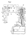
- a working cylinder 1 is formed in the machine housing of a 2-stroke diesel internal combustion engine, and then an exhaust duct 4 is formed in a separate housing 10 at its upper end.
- An outlet valve 2 is arranged in the housing 10 at the entrance of the exhaust duct 4 and, in the closed position shown, separates the combustion chamber 3 in the working cylinder 1 from the exhaust duct 4.
- a working piston 5 is guided up and down.
- the air to be compressed in the working cylinder is admitted into the cylinder chamber via slots (not shown) arranged in the lower region of the working cylinder 1 and is compressed in the combustion chamber 3 during the subsequent upward stroke of the working piston 5.
- the fuel is supplied with the aid of at least one injection nozzle (not shown) projecting into the combustion chamber 3.
- a piston 6 is arranged, which is guided in a cylinder 7 of the housing 10.
- a compressed air line 9 On the in Fig.1 located below the piston 6 cylinder space 7 'is connected via a check valve 8, a compressed air line 9. The air enclosed in this way in the cylinder space 7 'forms an air spring which acts on the exhaust valve 2 in a closing sense.
- the piston 6 in FIG. 1 acts via a rod 11 'a servo piston 11 actuated by a hydraulic pressure medium, which is guided in a servo cylinder 13 to which a hydraulic control device 12 is connected.
- the control device 12 has a pilot valve 15 designed as a 2/2-way valve and actuated by an electromagnet 14 and a 4/2-way valve 16.
- the hydraulic pressure medium for example oil, is supplied to the control device 12 via a line 17 from a pressure medium source 18 designed as an accumulator.
- the accumulator 18 receives the pressure medium from a reservoir 20 by means of a pump 19 which is driven by the crankshaft (not shown) of the internal combustion engine or electrically.
- the pressure medium in the accumulator 18 is under a pressure of, for example, 200 bar.
- the line 17 leading from the accumulator 18 to the control device 12 bifurcates in front of the 4/2-way valve 16 into two line branches 17 'and 17 ⁇ .
- the line branch 17 ⁇ contains a throttle point 22 and leads on the one hand to the pilot valve 15 and on the other hand to an end face of the 4/2-way valve 16.
- a relief line 24 which leads to the 4/2-way valve 16 and continues as a drain line 24 ', which opens into the reservoir 20 via a check valve 25.
- a vent line 26 which branches off from the servo cylinder 13 above the piston 11 and has a throttle point 57.
- a relief line 28 which starts from the pilot valve 15.
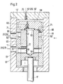
- the servo piston 11 has at its end facing away from the rod 11 'a blind bore 40 which is connected to an annular space 58 at its lower end in FIG. 1 in the region of the connection point 21 via transverse bores 56. In the area of the connection point 23 there is an annular space 59 between the servo piston 11 and the servo cylinder 13.
- a guide bush 60 is arranged between the servo cylinder 13 and the servo piston 11, each of which has a breakthrough in the area of the connection points 21 and 23 in the form of an outer annular groove 61 or 62 and a number of them starting from the circumference the guide sleeve has distributed radial bores 61 'and 62'.
- the guide sleeve 60 is axially movably guided in the servo cylinder 13 and has at its upper end in FIG. 2 a transverse wall 60 'in the form of a cover detachably connected to the guide sleeve.
- a radial channel 72 which opens into an outer annular groove 73 which during an opening process of the exhaust valve during the downward movement of the servo piston relative to the guide sleeve 60 in front of the bore 61 ' is coming.
- the upper end wall 13 'of the servo cylinder 13 in FIG. 2 has a connection point 67 for the vent line 26.
- a pressure medium-filled space 68 which communicates on the one hand via a check valve 69 closing against this space with the pressure chamber 65 and on the other hand via a check valve 70 closing against the connection point 67 with the relief line 26.
- the device according to Fig.2 works as follows. If the stem of the exhaust valve is extended due to an increase in temperature, the rod 11 'of the servo piston 11 is moved upwards in FIG. Since the upper end face of the servo piston 11 rests on the shoulder 63, the guide bush 60 is also displaced upward when the servo piston is moved. As a result of this displacement, pressure medium is displaced from the space 68 into the pressure space 65 via the check valve 69 which opens. The volume of pressure medium thus displaced escapes via the channels 71, 66, the annular groove 62 and the connection point 23 into the relief line 24.
Abstract
Description
Die Erfindung bezieht sich auf eine Vorrichtung zum hydraulischen Betätigen eines Auslassventils einer Hubkolbenbrennkraftmaschine, das an seinem dem Verschlussteil abgewendeten Ende mit einem in einem Servozylinder geführten Servokolben in Wirkungsverbindung steht, der im Arbeitstakt der Maschine von einem hydraulischen Druckmittel im Ventilöffnungssinn beaufschlagt ist, das über eine Druckmittelleitung von einer Druckmittelquelle einem Druckraum im Servozylinder zugeführt wird, an dem ausser der Druckmittelleitung eine Entlastungsleitung sowie eine Entlüftungsleitung angeschlossen sind.The invention relates to a device for hydraulically actuating an outlet valve of a reciprocating piston internal combustion engine, which at its end facing away from the closure part is operatively connected to a servo piston guided in a servo cylinder, which is acted upon by a hydraulic pressure medium in the valve opening direction during the work cycle of the machine, which is actuated via a Pressure medium line is fed from a pressure medium source to a pressure chamber in the servo cylinder, to which, in addition to the pressure medium line, a relief line and a ventilation line are connected.
Eine solche Vorrichtung ist aus der EP-OS 441 100 bekannt. Bei dieser Vorrichtung hat sich gezeigt, dass Längenänderungen des Auslassventilschaftes aufgrund von Temperaturänderungen die Dämpfungsphase beim Aufsetzen des Verschlussteils des Auslassventils auf seinen Sitz verändern, weil sich die Position des Servokolbens relativ zum Servozylinder verschiebt, was eine Aenderung des Schliesspunktes des Auslassventils zur Folge hat. Dadurch kann das Betriebsverhalten der Brennkraftmaschine ungünstig beeinflusst werden, insbesondere bei langhubigen Brennkraftmaschinen.Such a device is known from EP-OS 441 100. This device has shown that changes in the length of the exhaust valve stem due to temperature changes change the damping phase when the closure part of the exhaust valve is placed on its seat because the position of the servo piston moves relative to the servo cylinder, which results in a change in the closing point of the exhaust valve. This can adversely affect the operating behavior of the internal combustion engine, particularly in the case of long-stroke internal combustion engines.
Der Erfindung liegt die Aufgabe zugrunde, die Vorrichtung der eingangs genannten Art dahingehend zu verbessern, dass sich Schaftlängenänderungen des Auslassventils nicht mehr ungünstig auf dessen Schliessverhalten auswirken.The invention has for its object to improve the device of the type mentioned in such a way that changes in the length of the stem of the exhaust valve no longer have an adverse effect on its closing behavior.
Diese Aufgabe wird erfindungsgemäss dadurch gelöst, dass zwischen dem Servozylinder und dem Servokolben eine diesen umgebende, axial bewegliche Führungsbüchse angeordnet ist, die mindestens je einen mit dem Anschluss der Druckmittelleitung und dem Anschluss der Entlastungsleitung am Servozylinder kommunizierenden Durchbruch aufweist und die an ihrem dem Verschlussteil abgewendeten Ende durch eine Querwand dicht verschlossen ist, dass zwischen der Querwand und der Stirnwand des Servozylinders ein druckmittelgefüllter Raum besteht, der über ein gegen diesen Raum schliessendes Rückschlagventil mit dem Druckraum und über ein gegen die Entlüftungsleitung schliessendes Rückschlagventil mit der Entlüftungsleitung kommuniziert, und dass der Druckraum stets mit dem Anschluss für die Entlastungsleitung am Servozylinder in Verbindung steht.This object is achieved according to the invention in that between the servo cylinder and the servo piston there is an axially movable guide bush which surrounds this and which has at least one breakthrough communicating with the connection of the pressure medium line and the connection of the relief line on the servo cylinder, and the one facing away from the closure part End is sealed by a transverse wall that between the transverse wall and the front wall of the servo cylinder there is a pressure-filled space, which communicates with the pressure chamber via a check valve that closes against this space and communicates with the ventilation line via a check valve that closes against the ventilation line, and that the pressure chamber is always connected to the connection for the relief line on the servo cylinder.
Hierdurch wird erreicht, dass sich die Führungsbüchse bei Längenänderungen des Ventilschaftes in der gleichen Richtung und im gleichen Ausmass wie der Servokolben verschiebt, so dass die relative Zuordnung zwischen Servokolben und Führungsbüchse in jedem Fall erhalten bleibt. Schaftlängenänderungen des Auslassventils werden also in der Vorrichtung kompensiert, so dass die Oeffnungs- und Schliessgeometrie der Servovorrichtung des Auslassventils unabhängig von dessen Schaftlängenänderungen gleich bleibt.This ensures that the guide sleeve moves in the same direction and to the same extent as the servo piston when the length of the valve stem changes, so that the relative assignment between servo piston and guide sleeve is retained in any case. Changes in the length of the exhaust valve stem are thus compensated in the device, so that the opening and closing geometry of the servo device of the exhaust valve remains the same regardless of the changes in the length of the valve stem.
Ein Ausführungsbeispiel der Erfindung wird in der folgenden Beschreibung anhand der Zeichnung näher erläutert. Es zeigen:
- Fig.1 einen Vertikalschnitt durch den oberen Teil eines Arbeitszylinders mit einem Auslassventil sowie ein Schaltschema der Steuereinrichtung gemäss dem Stand der Technik und
- Fig.2 einen Axialschnitt durch einen Servozylinder mit Servokolben gemäss der Erfindung.
- 1 shows a vertical section through the upper part of a working cylinder with an outlet valve and a circuit diagram of the control device according to the prior art and
- 2 shows an axial section through a servo cylinder with servo pistons according to the invention.
Gemäss Fig.1 ist im Maschinengehäuse einer 2-Takt-Dieselbrennkraftmaschine ein Arbeitszylinder 1 und anschliessend an dessen oberen Ende in einem getrennten Gehäuse 10 ein Auspuffkanal 4 ausgebildet. Im Gehäuse 10 ist am Eingang des Auspuffkanals 4 ein Auslassventil 2 angeordnet, das in der gezeichneten geschlossenen Stellung den Brennraum 3 im Arbeitszylinder 1 vom Auspuffkanal 4 trennt. Im Arbeitszylinder 1 ist ein Arbeitskolben 5 auf- und abbeweglich geführt. Die im Arbeitszylinder zu komprimierende Luft wird über nicht dargestellte, im unteren Bereich des Arbeitszylinders 1 angeordnete Schlitze in den Zylinderraum eingelassen und beim anschliessenden Aufwärtshub des Arbeitskolbens 5 im Brennraum 3 verdichtet. Der Brennstoff wird mit Hilfe mindestens einer nicht dargestellten, in den Brennraum 3 ragenden Einspritzdüse zugeführt.According to FIG. 1, a working cylinder 1 is formed in the machine housing of a 2-stroke diesel internal combustion engine, and then an
An dem dem Brennraum 3 abgewendeten Ende des Auslassventils 2 ist ein Kolben 6 angeodnet, der in einem Zylinder 7 des Gehäuses 10 geführt ist. An dem in Fig.1 unterhalb des Kolbens 6 befindlichen Zylinderraum 7′ ist über ein Rückschlagventil 8 eine Druckluftleitung 9 angeschlossen. Die auf diese Weise im Zylinderraum 7′ eingeschlossene Luft bildet eine Luftfeder, die auf das Auslassventil 2 in schliessendem Sinne wirkt.At the end of the
Auf die in Fig.1 obere Seite des Kolbens 6 wirkt über eine Stange 11′ ein von einem hydraulischen Druckmittel betätigter Servokolben 11, der in einem Servozylinder 13 geführt ist, an dem eine hydraulische Steuereinrichtung 12 angeschlossen ist. Die Steuereinrichtung 12 weist ein als 2/2-Wegeventil ausgebildetes, durch einen Elektromagneten 14 betätigtes Vorsteuerventil 15 und ein 4/2-Wegeventil 16 auf. Das hydraulische Druckmittel, z.B. Oel, wird der Steuereinrichtung 12 über eine Leitung 17 von einer als Akkumulator ausgebildeten Druckmittelquelle 18 zugeführt. Der Akkumulator 18 erhält das Druckmittel aus einem Reservoir 20 mittels einer Pumpe 19, die von der nicht dargestellten Kurbelwelle der Brennkraftmaschine oder elektrisch angetrieben ist. Im Akkumulator 18 befindet sich das Druckmittel unter einem Druck von beispielsweise 200 bar. Die vom Akkumulator 18 zur Steuereinrichtung 12 führende Leitung 17 gabelt sich vor dem 4/2-Wegeventil 16 in zwei Leitungszweige 17′ und 17˝. Der Leitungszweig 17′ führt zum 4/2-Wegeventil 16 und setzt sich als Leitung 27 bis zu einer Anschlussstelle 21 am Servozylinder 13 fort. Der Leitungszweig 17˝ enthält eine Drosselstelle 22 und führt einerseits zum Vorsteuerventil 15 und andererseits auf eine Stirnseite des 4/2-Wegeventils 16. Am Servozylinder 13 befindet sich eine weitere Anschlussstelle 23 für eine Entlastungsleitung 24, die zum 4/2-Wegeventil 16 führt und sich als Ablaufleitung 24′ fortsetzt, die über ein Rückschlagventil 25 in das Reservoir 20 mündet. An die Ablaufleitung 24′ ist ausserdem eine Entlüftungsleitung 26 angeschlossen, die vom Servozylinder 13 oberhalb des Kolbens 11 abzweigt und eine Drosselstelle 57 aufweist. Stromoberhalb des Rückschlagventils 25 mündet in die Ablaufleitung 24′ eine Entlastungsleitung 28, die vom Vorsteuerventil 15 ausgeht.On the upper side of the
Der Servokolben 11 weist an seinem der Stange 11′ abgewendeten Ende eine Sackbohrung 40 auf, die an ihrem in Fig.1 unteren Ende im Bereich der Anschlussstelle 21 über Querbohrungen 56 mit einem Ringraum 58 in Verbindung steht. Im Bereich der Anschlussstelle 23 besteht zwischen dem Servokolben 11 und dem Servozylinder 13 ein Ringraum 59.The
In der in Fig.1 gezeichneten Stellung ist der Strom am Elektromagneten 14 des Vorsteuerventils 15 eingeschaltet, und das über den Leitungszweig 17˝ zugeführte Druckmittel wirkt auf die Stirnfläche des 4/2-Wegeventils 16; die Druckmittelzufuhr über den Leitungszweig 17′ und die Leitung 27 zum Servozylinder 13 ist dadurch abgesperrt. Hingegen hat das 4/2-Wegeventil 16 den Durchgang von der Entlastungsleitung 24 zur Ablaufleitung 24′ hergestellt, so dass der Servokolben 11 im Servozylinder 13 vom Druck des Druckmittels entlastet wird und das Auslassventil 2 von der Luftfeder unter dem Kolben 6 in schliessendem Sinne beeinflusst wird. Dabei wird Druckmittel aus dem Druckraum des Servozylinders über die Anschlussstelle 23 in die Entlastungsleitung 24 verdrängt. Wegen des Rückschlagventils 25 bleibt in dem stromoberhalb von diesem befindlichen Leitungsabschnitt 24′ sowie in den Leitungen 24 und 26 ein Restdruck von ungefähr 10 bar erhalten. Wird der Strom am Elektromagneten 14 ausgeschaltet, so wird im Vorsteuerventil 15 eine Verbindung zwischen dem Leitungszweig 17˝ und der Entlastungsleitung 28 hergestellt, so dass die Stirnfläche des 4/2-Wegeventils 16 vom Druck entlastet wird. Das 4/2-Wegeventil 16 unterbricht damit die vorherige Verbindung der Leitungen 24 und 24′ und verbindet nunmehr den Leitungszweig 17′ mit der Leitung 27, so dass unter Druck stehendes Druckmittel über die Anschlussstelle 21, den Raum 58 und die Querbohrungen 56 in die Sackbohrung 40 gelangt, wodurch der Servokolben 11 abwärtsbewegt wird und das Auslassventil 2 öffnet.In the position shown in Figure 1, the current at the
Wie Fig.2 zeigt, ist erfindungsgemäss zwischen dem Servozylinder 13 und dem Servokolben 11 eine Führungsbüchse 60 angeordnet, die im Bereich der Anschlussstellen 21 und 23 jeweils einen Durchbruch in Form einer äusseren Ringnut 61 bzw. 62 und mehreren von dieser ausgehenden, über den Umfang der Führungsbüchse verteilten radialen Bohrungen 61′ bzw. 62′ aufweist. Die Führungsbüchse 60 ist im Servozylinder 13 axial beweglich geführt und weist an ihrem in Fig.2 oberen Ende eine Querwand 60′ in Form eines lösbar mit der Führungsbüchse verbundenen Deckels auf. In der Führungsbüchse 60 ist der Servokolben 11 gleitend gelagert, der in der in Fig.2 gezeichneten Stellung mit seiner oberen Stirnfläche an einem Ansatz 63 des Deckels 60′ anliegt. Von dem so gebildeten Druckraum 65 zwischen dem Servokolben 11 und der Führungsbüchse 60, 60′ zweigen zwei den Ansatz 63 durchdringende radiale Kanäle 71 ab, die über eine zwischen den äusseren Stirnkanten des Ansatzes 63 und des Servokolbens 11 ausgebildete Ringnut in einen die Führungsbüchse 60 durchdringenden winkelförmigen Kanal 66 münden, der seinerseits in eine der oberen Bohrungen 62′ mündet. Dadurch ist eine ständige Verbindung zwischen dem Druckraum 65 und der an der Stelle 23 angeschlossenen Entlastungsleitung 24 hergestellt ist. Im Servokolben 11 befindet sich etwas oberhalb der in Fig.2 linken Bohrung 56 ein radialer Kanal 72, der in eine äussere Ringnut 73 mündet, die während eines Oeffnungsvorganges des Auslassventils bei der Abwärtsbewegung des Servokolbens relativ zur Führungsbüchse 60 vor die Bohrung 61′ zu liegen kommt.As shown in FIG. 2, according to the invention, a
Die in Fig.2 obere Stirnwand 13′ des Servozylinders 13 weist eine Anschlussstelle 67 für die Entlüftungsleitung 26 auf. Zwischen der Stirnwand 13′ und dem Deckel 60′ befindet sich ein druckmittelgefüllter Raum 68, der einerseits über ein gegen diesen Raum schliessendes Rückschlagventil 69 mit dem Druckraum 65 und andererseits über ein gegen die Anschlussstelle 67 schliessendes Rückschlagventil 70 mit der Entlastungsleitung 26 kommuniziert.The upper end wall 13 'of the
Die Vorrichtung gemäss Fig.2 funktioniert wie folgt. Wenn sich der Schaft des Auslassventils infolge Temperaturerhöhung verlängert, so wird über die Stange 11′ der Servokolben 11 in Fig.2 nach oben verschoben. Da die obere Stirnfläche des Servokolbens 11 am Ansatz 63 anliegt, wird mit der Verschiebung des Servokolbens zugleich auch die Führungsbüchse 60 nach oben verschoben. Durch diese Verschiebung wird Druckmittel aus dem Raum 68 über das sich öffnende Rückschlagventil 69 in den Druckraum 65 verdrängt. Das so verdrängte Druckmittelvolumen entweicht über die Kanäle 71, 66, die Ringnut 62 und die Anschlussstelle 23 in die Entlastungsleitung 24. Auf diese Weise bleibt trotz der Längenänderung des Auslassventilschaftes die relative Lage des Servokolbens 11 zur Führungsbüchse 60 erhalten, und es kann keine Veränderung des Schliessverhaltens des Auslassventils eintreten. Auch bei einer Verkürzung des Schaftes des Auslassventils tritt diese Wirkung ein, indem die Stange 11′ der Schaftverkürzung folgt. Da der Durchmesser der Querwand 60′ der Führungsbüchse 60 grösser ist als der Durchmesser des Servokolbens 11 sowie infolge des früher erwähnten Restdruckes entsteht im Raum 68 eine hydraulische Kraft, die die Führungsbüchse in Fig.2 abwärtsbewegt und den Anschlag 63 wieder gegen den Servokolben drückt. Durch Oeffnen des Rückschlagventils 70 strömt Druckmittel aus der Entlüftungsleitung 26 in den Raum 68 nach. Auch in diesem Fall bleiben also die relative Lage des Servokolbens 11 zur Führungsbüchse 60 und damit auch das Schliessverhalten des Auslassventils erhalten.The device according to Fig.2 works as follows. If the stem of the exhaust valve is extended due to an increase in temperature, the
Claims (2)
Applications Claiming Priority (2)
| Application Number | Priority Date | Filing Date | Title |
|---|---|---|---|
| CH309891 | 1991-10-23 | ||
| CH3098/91 | 1991-10-23 |
Publications (2)
| Publication Number | Publication Date |
|---|---|
| EP0539320A1 true EP0539320A1 (en) | 1993-04-28 |
| EP0539320B1 EP0539320B1 (en) | 1995-01-11 |
Family
ID=4248578
Family Applications (1)
| Application Number | Title | Priority Date | Filing Date |
|---|---|---|---|
| EP92810735A Expired - Lifetime EP0539320B1 (en) | 1991-10-23 | 1992-09-30 | Device for hydraulically operating an exhaust valve of an internal combustion piston engine |
Country Status (6)
| Country | Link |
|---|---|
| EP (1) | EP0539320B1 (en) |
| JP (1) | JP3564149B2 (en) |
| KR (1) | KR100222139B1 (en) |
| CN (1) | CN1032381C (en) |
| DE (1) | DE59201193D1 (en) |
| DK (1) | DK0539320T3 (en) |
Cited By (3)
| Publication number | Priority date | Publication date | Assignee | Title |
|---|---|---|---|---|
| WO1996004469A1 (en) * | 1994-08-04 | 1996-02-15 | Caterpillar Inc. | Hydraulically actuated valve system |
| EP1114918A2 (en) | 2000-01-06 | 2001-07-11 | Wärtsilä NSD Schweiz AG | Valve arrangement for an internal combustion engine and driving method |
| WO2002006641A1 (en) * | 2000-07-14 | 2002-01-24 | Lotus Cars Limited | A hydraulic valve system for controlling flow of gas into or out of a variable volume chamber of an internal combustion engine or compressor |
Families Citing this family (8)
| Publication number | Priority date | Publication date | Assignee | Title |
|---|---|---|---|---|
| DE10311493B4 (en) * | 2003-03-15 | 2005-01-05 | Man B & W Diesel A/S | Two-stroke diesel engine |
| ITBO20030389A1 (en) * | 2003-06-23 | 2004-12-24 | Magneti Marelli Powertrain Spa | ELECTROHYDRAULIC VALVE OPERATION GROUP |
| DE10361221B4 (en) * | 2003-12-24 | 2006-03-09 | Man B&W Diesel A/S | Device for controlling the time-shifted connection of two acted upon by a pressure medium units with a pressure medium source |
| US7290509B2 (en) * | 2005-08-01 | 2007-11-06 | Zheng Lou | Variable valve actuator |
| US7587863B2 (en) * | 2006-08-17 | 2009-09-15 | Fike Corporation | Seal for sanitary overpressure vent structure |
| CN102787878B (en) * | 2012-07-27 | 2014-07-30 | 长城汽车股份有限公司 | Hydraulic drive engine air distributing mechanism |
| CN105756739B (en) * | 2016-05-04 | 2018-05-18 | 哈尔滨工程大学 | Electromagnetic hydraulic pressure drive-type air distribution system |
| CN109372607A (en) * | 2018-10-23 | 2019-02-22 | 中船动力研究院有限公司 | Multistage draining exhaust valve and its working method |
Citations (2)
| Publication number | Priority date | Publication date | Assignee | Title |
|---|---|---|---|---|
| DE3809954C1 (en) * | 1988-03-24 | 1989-08-24 | Bayerische Motoren Werke Ag, 8000 Muenchen, De | Device for the hydraulic opening of a lifting valve |
| EP0441100A1 (en) * | 1990-02-08 | 1991-08-14 | GebràDer Sulzer Aktiengesellschaft | Device for controlling the exhaust valve of an internal combustion piston engine |
-
1992
- 1992-09-30 DE DE59201193T patent/DE59201193D1/en not_active Expired - Lifetime
- 1992-09-30 DK DK92810735.8T patent/DK0539320T3/en active
- 1992-09-30 EP EP92810735A patent/EP0539320B1/en not_active Expired - Lifetime
- 1992-10-19 KR KR1019920019138A patent/KR100222139B1/en not_active IP Right Cessation
- 1992-10-22 JP JP28463892A patent/JP3564149B2/en not_active Expired - Fee Related
- 1992-10-22 CN CN92112269A patent/CN1032381C/en not_active Expired - Fee Related
Patent Citations (2)
| Publication number | Priority date | Publication date | Assignee | Title |
|---|---|---|---|---|
| DE3809954C1 (en) * | 1988-03-24 | 1989-08-24 | Bayerische Motoren Werke Ag, 8000 Muenchen, De | Device for the hydraulic opening of a lifting valve |
| EP0441100A1 (en) * | 1990-02-08 | 1991-08-14 | GebràDer Sulzer Aktiengesellschaft | Device for controlling the exhaust valve of an internal combustion piston engine |
Cited By (6)
| Publication number | Priority date | Publication date | Assignee | Title |
|---|---|---|---|---|
| WO1996004469A1 (en) * | 1994-08-04 | 1996-02-15 | Caterpillar Inc. | Hydraulically actuated valve system |
| EP1114918A2 (en) | 2000-01-06 | 2001-07-11 | Wärtsilä NSD Schweiz AG | Valve arrangement for an internal combustion engine and driving method |
| WO2002006641A1 (en) * | 2000-07-14 | 2002-01-24 | Lotus Cars Limited | A hydraulic valve system for controlling flow of gas into or out of a variable volume chamber of an internal combustion engine or compressor |
| GB2380522A (en) * | 2000-07-14 | 2003-04-09 | Lotus Car | A hydraulic valve system for controlling flow of gas into or out of a variable volume chamber of an internal combustion engine or compressor |
| GB2380522B (en) * | 2000-07-14 | 2004-05-12 | Lotus Car | A hydraulic valve system for controlling flow of gas into or out of a variable volume chamber of an internal combustion engine or compressor |
| US6772718B2 (en) | 2000-07-14 | 2004-08-10 | Lotus Cars Limited | Hydraulic valve system for controlling flow of gas into or out of a variable volume chamber of an internal combustion engine or compressor |
Also Published As
| Publication number | Publication date |
|---|---|
| KR100222139B1 (en) | 1999-10-01 |
| KR930008317A (en) | 1993-05-21 |
| CN1032381C (en) | 1996-07-24 |
| CN1071733A (en) | 1993-05-05 |
| JPH05195731A (en) | 1993-08-03 |
| DE59201193D1 (en) | 1995-02-23 |
| JP3564149B2 (en) | 2004-09-08 |
| DK0539320T3 (en) | 1995-03-20 |
| EP0539320B1 (en) | 1995-01-11 |
Similar Documents
| Publication | Publication Date | Title |
|---|---|---|
| WO2011009879A1 (en) | Method for controlling delivery quantity, and reciprocating compressor having delivery quantity control | |
| DE3247420C2 (en) | ||
| DE3714762C2 (en) | ||
| EP0539320B1 (en) | Device for hydraulically operating an exhaust valve of an internal combustion piston engine | |
| EP0562286A1 (en) | Exhaust valve control device for engine braking | |
| DE2732063C2 (en) | Working piston to change the compression | |
| DE10155669A1 (en) | Device for controlling at least one gas exchange valve | |
| EP0455763B1 (en) | Hydraulic control device for the valves of a multi-cylinder internal-combustion engine | |
| DE4118555A1 (en) | CONVEYOR ADJUSTMENT DEVICE OF A FUEL INJECTION PUMP | |
| CH681825A5 (en) | ||
| EP0441100B1 (en) | Device for controlling the exhaust valve of an internal combustion piston engine | |
| DE2011600B2 (en) | Hydraulic drop hammer | |
| EP0193142A1 (en) | Engine-braking system for an internal-combustion engine | |
| DE1751703A1 (en) | Piston arrangement with changeable compression ratio | |
| DE3044255C2 (en) | ||
| EP2456979B1 (en) | Method for controlling delivery quantity, and reciprocating compressor having delivery quantity control | |
| DE3625664C2 (en) | ||
| DE1809160A1 (en) | Inlet valve for pistons with changeable compression ratio | |
| DE19527719A1 (en) | Fuel injection system | |
| DE4427271B4 (en) | Valve drive for a cam-operated, spring-loaded globe valve | |
| DE19604455B4 (en) | Pneumatic valve control for internal combustion engines | |
| DE60217753T2 (en) | Control valve system | |
| EP3557013B1 (en) | Hydraulic valve drive for a cylinder valve of a combustion engine | |
| DE625629C (en) | Fuel injector | |
| DE4202507A1 (en) | Variable lift valve drive - has pressure control element integrated with cup-shaped piston |
Legal Events
| Date | Code | Title | Description |
|---|---|---|---|
| PUAI | Public reference made under article 153(3) epc to a published international application that has entered the european phase |
Free format text: ORIGINAL CODE: 0009012 |
|
| AK | Designated contracting states |
Kind code of ref document: A1 Designated state(s): CH DE DK FR IT LI |
|
| 17P | Request for examination filed |
Effective date: 19930622 |
|
| 17Q | First examination report despatched |
Effective date: 19931122 |
|
| GRAA | (expected) grant |
Free format text: ORIGINAL CODE: 0009210 |
|
| AK | Designated contracting states |
Kind code of ref document: B1 Designated state(s): CH DE DK FR IT LI |
|
| RIN1 | Information on inventor provided before grant (corrected) |
Inventor name: WUNDER, ALFRED FRANZ |
|
| REF | Corresponds to: |
Ref document number: 59201193 Country of ref document: DE Date of ref document: 19950223 |
|
| ITF | It: translation for a ep patent filed |
Owner name: ING. ZINI MARANESI & C. S.R.L. |
|
| REG | Reference to a national code |
Ref country code: DK Ref legal event code: T3 |
|
| ET | Fr: translation filed | ||
| PG25 | Lapsed in a contracting state [announced via postgrant information from national office to epo] |
Ref country code: LI Effective date: 19950930 Ref country code: CH Effective date: 19950930 |
|
| PLBE | No opposition filed within time limit |
Free format text: ORIGINAL CODE: 0009261 |
|
| STAA | Information on the status of an ep patent application or granted ep patent |
Free format text: STATUS: NO OPPOSITION FILED WITHIN TIME LIMIT |
|
| 26N | No opposition filed | ||
| REG | Reference to a national code |
Ref country code: CH Ref legal event code: PL |
|
| PGFP | Annual fee paid to national office [announced via postgrant information from national office to epo] |
Ref country code: DK Payment date: 20090910 Year of fee payment: 18 |
|
| PGFP | Annual fee paid to national office [announced via postgrant information from national office to epo] |
Ref country code: DE Payment date: 20090922 Year of fee payment: 18 |
|
| PGFP | Annual fee paid to national office [announced via postgrant information from national office to epo] |
Ref country code: IT Payment date: 20090926 Year of fee payment: 18 |
|
| REG | Reference to a national code |
Ref country code: DK Ref legal event code: EBP |
|
| PG25 | Lapsed in a contracting state [announced via postgrant information from national office to epo] |
Ref country code: IT Free format text: LAPSE BECAUSE OF NON-PAYMENT OF DUE FEES Effective date: 20100930 |
|
| REG | Reference to a national code |
Ref country code: FR Ref legal event code: ST Effective date: 20110531 |
|
| REG | Reference to a national code |
Ref country code: DE Ref legal event code: R119 Ref document number: 59201193 Country of ref document: DE Effective date: 20110401 |
|
| PG25 | Lapsed in a contracting state [announced via postgrant information from national office to epo] |
Ref country code: DE Free format text: LAPSE BECAUSE OF NON-PAYMENT OF DUE FEES Effective date: 20110401 Ref country code: FR Free format text: LAPSE BECAUSE OF NON-PAYMENT OF DUE FEES Effective date: 20100930 |
|
| PGFP | Annual fee paid to national office [announced via postgrant information from national office to epo] |
Ref country code: FR Payment date: 20091001 Year of fee payment: 18 |
|
| PG25 | Lapsed in a contracting state [announced via postgrant information from national office to epo] |
Ref country code: DK Free format text: LAPSE BECAUSE OF NON-PAYMENT OF DUE FEES Effective date: 20100930 |