EP0539266A1 - Übertragung und elektrisches Umwandlungssystem von frequenzmodulierter hoher Leistung optischer Signale - Google Patents
Übertragung und elektrisches Umwandlungssystem von frequenzmodulierter hoher Leistung optischer Signale Download PDFInfo
- Publication number
- EP0539266A1 EP0539266A1 EP92402789A EP92402789A EP0539266A1 EP 0539266 A1 EP0539266 A1 EP 0539266A1 EP 92402789 A EP92402789 A EP 92402789A EP 92402789 A EP92402789 A EP 92402789A EP 0539266 A1 EP0539266 A1 EP 0539266A1
- Authority
- EP
- European Patent Office
- Prior art keywords
- optical
- pyroelectric element
- transmission
- photo
- energy
- Prior art date
- Legal status (The legal status is an assumption and is not a legal conclusion. Google has not performed a legal analysis and makes no representation as to the accuracy of the status listed.)
- Withdrawn
Links
Images


Classifications
-
- H—ELECTRICITY
- H04—ELECTRIC COMMUNICATION TECHNIQUE
- H04B—TRANSMISSION
- H04B10/00—Transmission systems employing electromagnetic waves other than radio-waves, e.g. infrared, visible or ultraviolet light, or employing corpuscular radiation, e.g. quantum communication
- H04B10/80—Optical aspects relating to the use of optical transmission for specific applications, not provided for in groups H04B10/03 - H04B10/70, e.g. optical power feeding or optical transmission through water
- H04B10/806—Arrangements for feeding power
- H04B10/807—Optical power feeding, i.e. transmitting power using an optical signal
Definitions
- the present invention relates to a system for the electrical transmission and conversion of frequency modulated power optical signals. It applies in particular to embodiments of coded optical remote power supplies capable of transmitting sufficient energy for a very short time while remaining insensitive to unfavorable environments such as electromagnetic disturbances for example, these remote power supplies further allowing, taking into account of their high cut-off frequency, the simultaneous passage of binary information coded in very high frequencies. More generally, the invention applies to any transmission of optical energy whose reception area is relatively small.
- the optical link insensitive to electromagnetic disturbances, makes it possible to simplify the connections between these blocks of elements.
- the optical path requires the implementation of devices converting optical energy into electrical energy capable simultaneously of accepting high optical powers, of having high conversion yields and short response times.
- these properties cannot be obtained simultaneously in conventional photo-detectors based on semiconductors, for example silicon, germanium or gallium arsenide. Indeed, these reception and conversion elements do not tolerate optical power densities greater than about.
- the object of the invention is to overcome the aforementioned drawbacks.
- the subject of the invention is a system for the electrical transmission and conversion of frequency modulated power optical signals comprising at least one source of optical energy, optical means for transmitting and collecting the optical power signals transmitted. by the source and means for receiving and converting optical signals into electrical signals characterized in that that the reception and conversion means comprise at least one pyroelectric element.
- the main advantages of the invention are that it allows the simultaneous transmission of high power optical streams through small reception areas and very high bit rate binary coded information, independently of the electromagnetic environment, and that it is easily adaptable to any architecture of the transmission network.
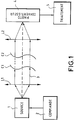
- FIG. 1 represents a basic known structure of an optical energy transmission system. It is composed of an optical energy source 1 associated with electronic control circuits 2, an optical link 3 in an aerial optical beam for example comprising in particular optical collection means, including lenses L1 and L2 for example, a photo-converter 4 and electronic processing and extraction circuits 5.
- the photo-converter is for example made from semiconductors.
- the dotted lines between the curved lines C1 and C2 symbolize the length of the optical link which is not defined a priori, which can go from a few centimeters to several tens of meters for example.
- the part containing the optical energy source may be integral or non-integral with the photo-conversion and processing part, and driven by a translational or rotational movement relative to this part.
- FIG. 2a presents a possible embodiment of an optical energy transmission system according to the invention.
- This system allows the conversion into electrical energy of an optical power signal transmitted by the link 3 from the source 1.
- This optical power signal is modulated at a frequency f and converted into an electrical power signal by means of a pyroelectric element 6 whose thermal cutoff frequency is much higher than the modulation frequency of the transmitted optical signal.
- the modulation of the power signal allows in particular the coding and the transfer of binary information.
- the modulation frequency of this signal can reach 10 to 100 MHz.
- the advantage provided by this pyroelectric element 6 is that it accepts higher power densities than conventional photo-converters, this power density can be of the order of and even more, according to the possible structures adopted for the pyroelectric element 6.
- the energy converted by the pyroelectric element can be used in particular to activate an auxiliary device or any other part needing a activation energy.
- the pyroelectric element 6 is located so as to receive the maximum of energy from the light energy reception device constituted for example by a lens L2, F2 constituting the focus of this lens.
- the receiving face of the pyroelectric element 6 coincides with a plane parallel to the lens F2.
- binary coded information is transmitted.
- the optical power signal can be frequency modulated, this modulation making it possible to contain the coded information. cited above.
- This receiver can accept power densities of approximately , which is more than enough for the low power required to use the binary coded information on reception.
- This photo-receptor 7 can be produced based on silicon or gallium arsenide for example. It is arranged outside the cone 9 of exit from the lens L2 so that only the scattered light remains symbolized by the dotted line 10, low energy but always modulated according to the frequency f.
- the optical link 3 can be produced by optical power fibers, with a diameter of approximately 500 ⁇ m to 1 mm, or produced by an aerial optical beam. In the case of an optical fiber, means of capturing the light ray must be located at the arrival and coupled to the pyroelectric element 6. The choice depends in particular on the type of application. Processing circuits 5 associated with the pyroelectric element 6 and with the photo-receiver 7 allow the shaping of the electrical energy stored in the pyroelectric element 6 and the shaping of the signals of high bit rates of captured coded information by the photo-receptor 7.
- FIG. 2b represents a detailed view of the photo-reception device of FIG. 2a produced according to the invention and consisting of elements 6 and 7.
- the pyroelectric element 6 comprises two electrodes 13 and 14 of opposite signs making it possible to collect the charges created during the absorption of the optical signal of internal power at the cone 9. These charges cause the appearance of a voltage between these two electrodes and constitute the electrical source of converted power.
- a layer 15 of broadband optical absorbent is placed on the receiving face 8 of the pyroelectric element 6 so as to attenuate or even eliminate the reflections of the optical power signal inside the cone 9
- the element pyroelectric 6 can be constituted for example based on barium titanate ceramics, zirconium titanium lead, lithium niobate or composites based on ferroelectric powder mixed with a plastic binder known to those skilled in the art, pyroelectric element 6 can also be formed for example based on polymers of polyvinylidene fluoride, polyvinylidene trifluoroethylene or a mixture of the two.
- this pyroelectric element 6 is placed on a support 16 marked by hatching, the axis of symmetry 17 indicates its symmetry of revolution.
- the associated photovoltaic element 7 intended to receive the diffused light 10 comprises in particular an optical window 11 and a photo-receiving zone 12; its establishment time is of the order of 10 ns.
- FIG. 3 illustrates a variant of the structure described by FIGS. 2a and 2b.
- the low-power photo-receiver 7 consisting for example of a photovoltaic element, is located in the center of the power photo-reception device constituted by the pyroelectric element 6.
- the low-power photo-receiver 7 being in look at the face 21 of the pyroelectric element, opposite the receiving face 8.
- the light energy is transmitted for example by means of an optical fiber 19 passing through the pyroelectric element 6 along its axis of symmetry.
- the low power photo-receiver 7 captures the scattered light included in the cone 20 at the output of the optical fiber 19 passing through the pyroelectric element.
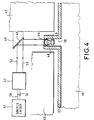
- FIG. 4 illustrates a possible application of a system for transmitting and converting optical energy according to the invention.
- a device consists of two parts 45 and 46.
- the first part 45 contains for example a source 41 of YAG type power laser for example, emitting a frequency modulated beam delimited by the lines 50 and 51, this beam is widened by an expansion device 42 and delimited by lines 52 and 53. It is reflected on a mirror 43 held integral with the first part 45 by a support 49 then is captured by a spherical lens 44 integral with the second part 46.
- This lens disposed at the front of the pyroelectric element 6 concentrates inside a cone 48 the optical power flow on the receiving face of the pyroelectric element which converts it into electric energy.
- the spherical lens 44 and the pyroelectric element 6 are for example fixed in a receiving cylinder 50 seen in section in FIG. 4, this cylinder being an extension of the second part 46 penetrating inside the first part 45 with a play large enough to support the small relative displacements between the two parts 45 and 46.
- the beam expander 42 makes it possible to compensate for these slight relative displacements of the second part 46 relative to the first part 45 so that during such displacements , a large part of the energy remains captured by the lens 44.
- the hatched part 57 illustrates the thickness of the second part 46 and of the receiving cylinder 50.
- the low power receiver 4 can for example transfer an energy of 1 joule in less than 100 ms, the reception surfaces of the spherical lens 44 and of the pyroelectric element 6 being of the order of one square centimeter.
- the low power receiver has not been shown for reasons of clarity but each of the solutions presented using the previous figures can be used.
- the invention advantageously applies to any system where it is necessary, for reasons of security and resistance to hostile environments, that at least part of the system, an aircraft for example, have the information and the energy necessary for the activation of one or more other sensitive part (s), for example ammunition, the latter having the energy potential to function but remaining inert without the sending by the first part, both of an energy of startup and binary information of commands and configuration, this transmission must also meet severe environmental constraints.
- the invention applies to any system in which at a given time in operational mode, two elements of this system are capable of separating with great security, for example in the case of stages of aerospace launchers.
Landscapes
- Physics & Mathematics (AREA)
- Electromagnetism (AREA)
- Engineering & Computer Science (AREA)
- Computer Networks & Wireless Communication (AREA)
- Signal Processing (AREA)
- Optical Communication System (AREA)
Applications Claiming Priority (2)
| Application Number | Priority Date | Filing Date | Title |
|---|---|---|---|
| FR9113217 | 1991-10-25 | ||
| FR9113217A FR2683106B1 (fr) | 1991-10-25 | 1991-10-25 | Systeme de transmission et de conversion electrique de signaux optiques de puissance modules en frequence. |
Publications (1)
| Publication Number | Publication Date |
|---|---|
| EP0539266A1 true EP0539266A1 (de) | 1993-04-28 |
Family
ID=9418334
Family Applications (1)
| Application Number | Title | Priority Date | Filing Date |
|---|---|---|---|
| EP92402789A Withdrawn EP0539266A1 (de) | 1991-10-25 | 1992-10-13 | Übertragung und elektrisches Umwandlungssystem von frequenzmodulierter hoher Leistung optischer Signale |
Country Status (3)
| Country | Link |
|---|---|
| EP (1) | EP0539266A1 (de) |
| CA (1) | CA2081091A1 (de) |
| FR (1) | FR2683106B1 (de) |
Cited By (2)
| Publication number | Priority date | Publication date | Assignee | Title |
|---|---|---|---|---|
| EP0924880A1 (de) * | 1997-12-17 | 1999-06-23 | Siemens Aktiengesellschaft | System zur kabellosen optischen Energie- und Datenübertragung |
| EP1276220A3 (de) * | 2001-06-26 | 2004-01-14 | Hewlett-Packard Company | Stromversorgung mit pyroelektrischen Kondensator |
Family Cites Families (2)
| Publication number | Priority date | Publication date | Assignee | Title |
|---|---|---|---|---|
| JPS5767828A (en) * | 1980-10-15 | 1982-04-24 | Kureha Chem Ind Co Ltd | Photodetector |
| JPS6133032A (ja) * | 1984-07-26 | 1986-02-15 | Toshiba Eng Co Ltd | 光通信装置 |
-
1991
- 1991-10-25 FR FR9113217A patent/FR2683106B1/fr not_active Expired - Fee Related
-
1992
- 1992-10-13 EP EP92402789A patent/EP0539266A1/de not_active Withdrawn
- 1992-10-21 CA CA 2081091 patent/CA2081091A1/fr not_active Abandoned
Non-Patent Citations (3)
| Title |
|---|
| IEEE TRANSACTIONS ON POWER DELIVERY. vol. 4, no. 4, Octobre 1989, NEW YORK US pages 1997 - 2004 H.KIRKHAM ET AL 'Optically powered data link for power system applications' * |
| PATENT ABSTRACTS OF JAPAN vol. 10, no. 186 (E-416)(2242) 28 Juin 1986 & JP-A-61 033 032 ( TOSHIBA ENG ) * |
| PATENT ABSTRACTS OF JAPAN vol. 6, no. 148 (P-133)7 Août 1982 & JP-A-57 067 828 ( KUREHA CHEM ) 24 Avril 1982 * |
Cited By (3)
| Publication number | Priority date | Publication date | Assignee | Title |
|---|---|---|---|---|
| EP0924880A1 (de) * | 1997-12-17 | 1999-06-23 | Siemens Aktiengesellschaft | System zur kabellosen optischen Energie- und Datenübertragung |
| WO1999031829A1 (de) * | 1997-12-17 | 1999-06-24 | Siemens Aktiengesellschaft | System zur kabellosen optischen energie- und datenübertragung |
| EP1276220A3 (de) * | 2001-06-26 | 2004-01-14 | Hewlett-Packard Company | Stromversorgung mit pyroelektrischen Kondensator |
Also Published As
| Publication number | Publication date |
|---|---|
| FR2683106A1 (fr) | 1993-04-30 |
| CA2081091A1 (fr) | 1993-04-26 |
| FR2683106B1 (fr) | 1993-12-03 |
Similar Documents
| Publication | Publication Date | Title |
|---|---|---|
| FR2482390A1 (fr) | Systeme de transmission optique de signaux pour un vehicule automobile | |
| EP0817408B1 (de) | Empfänger für Übertragungssystem eines optischen Digitalsignals | |
| FR2581768A1 (fr) | Composant optoelectrique bidirectionnel formant coupleur optique | |
| EP0278835B1 (de) | System zur optischen Abstandsteuerung einer elektrischen Vorrichtung | |
| EP0282766A1 (de) | Aktives optisches Steckergehäuse | |
| EP0586285B1 (de) | Optischer Sender-Empfänger für optische Datenübertragung und Schalteinrichtung | |
| EP0247940B1 (de) | Überwachungsvorrichtung mit Lichtwellenleiter | |
| EP0002971B1 (de) | Kopplungsanordnung für eine optische Übertragungsleitung und solche Anordnungen enthaltendes Übertragungssystem | |
| EP0539266A1 (de) | Übertragung und elektrisches Umwandlungssystem von frequenzmodulierter hoher Leistung optischer Signale | |
| FR2626966A1 (fr) | Dispositif capteur de rayons solaires | |
| JPS6315846Y2 (de) | ||
| FR2575285A1 (fr) | Codeur optique de reperage de position | |
| CN1158792C (zh) | 双向光通信用模块 | |
| FR2478849A1 (fr) | Carte portative d'identification et systeme de traitement mettant en oeuvre une telle carte | |
| FR2831344A1 (fr) | Systeme de distribution d'alimentation fonde sur un conduit de communication a lumiere | |
| FR2688319A1 (fr) | Coupleur optique a haute isolation. | |
| FR2523733A1 (fr) | Dispositif pour la transmission et la distribution de rayonnement lumineux | |
| EP0106710B1 (de) | Optische Schalteinrichtung | |
| EP0198761A1 (de) | Optischer Koppler, seine Anwendung in einer faseroptischen Drehkupplung und Verfahren zu seiner Herstellung | |
| FR2513049A1 (fr) | Systeme de communication optique et reseau telephonique comprenant un tel systeme | |
| EP1756639B1 (de) | Optischer, elektromagnetische wellen verstärkender konzentrator | |
| FR2546012A1 (fr) | Procede de transmission bidirectionnelle de donnees par fibre optique sur un bus serie et dispositif terminal connecte a ce bus pour la mise en oeuvre de ce procede | |
| US20030075672A1 (en) | Method and apparatus for coupling optical fiber with photodetectors | |
| CA2434597A1 (fr) | Coupleur optique | |
| EP1225465B1 (de) | Optische Vorrichtung |
Legal Events
| Date | Code | Title | Description |
|---|---|---|---|
| PUAI | Public reference made under article 153(3) epc to a published international application that has entered the european phase |
Free format text: ORIGINAL CODE: 0009012 |
|
| AK | Designated contracting states |
Kind code of ref document: A1 Designated state(s): DE GB IT SE |
|
| 17P | Request for examination filed |
Effective date: 19930622 |
|
| STAA | Information on the status of an ep patent application or granted ep patent |
Free format text: STATUS: THE APPLICATION IS DEEMED TO BE WITHDRAWN |
|
| 18D | Application deemed to be withdrawn |
Effective date: 19950503 |