EP0539182A1 - Procédé pour la fabrication d'articles moulés à partir de résines renforcées par des fibres - Google Patents
Procédé pour la fabrication d'articles moulés à partir de résines renforcées par des fibres Download PDFInfo
- Publication number
- EP0539182A1 EP0539182A1 EP92309624A EP92309624A EP0539182A1 EP 0539182 A1 EP0539182 A1 EP 0539182A1 EP 92309624 A EP92309624 A EP 92309624A EP 92309624 A EP92309624 A EP 92309624A EP 0539182 A1 EP0539182 A1 EP 0539182A1
- Authority
- EP
- European Patent Office
- Prior art keywords
- resin material
- fibre
- cavity
- mould
- liquid resin
- Prior art date
- Legal status (The legal status is an assumption and is not a legal conclusion. Google has not performed a legal analysis and makes no representation as to the accuracy of the status listed.)
- Granted
Links
Images


Classifications
-
- B—PERFORMING OPERATIONS; TRANSPORTING
- B29—WORKING OF PLASTICS; WORKING OF SUBSTANCES IN A PLASTIC STATE IN GENERAL
- B29C—SHAPING OR JOINING OF PLASTICS; SHAPING OF MATERIAL IN A PLASTIC STATE, NOT OTHERWISE PROVIDED FOR; AFTER-TREATMENT OF THE SHAPED PRODUCTS, e.g. REPAIRING
- B29C37/00—Component parts, details, accessories or auxiliary operations, not covered by group B29C33/00 or B29C35/00
- B29C37/005—Compensating volume or shape change during moulding, in general
-
- B—PERFORMING OPERATIONS; TRANSPORTING
- B29—WORKING OF PLASTICS; WORKING OF SUBSTANCES IN A PLASTIC STATE IN GENERAL
- B29C—SHAPING OR JOINING OF PLASTICS; SHAPING OF MATERIAL IN A PLASTIC STATE, NOT OTHERWISE PROVIDED FOR; AFTER-TREATMENT OF THE SHAPED PRODUCTS, e.g. REPAIRING
- B29C70/00—Shaping composites, i.e. plastics material comprising reinforcements, fillers or preformed parts, e.g. inserts
- B29C70/04—Shaping composites, i.e. plastics material comprising reinforcements, fillers or preformed parts, e.g. inserts comprising reinforcements only, e.g. self-reinforcing plastics
- B29C70/28—Shaping operations therefor
- B29C70/40—Shaping or impregnating by compression not applied
- B29C70/42—Shaping or impregnating by compression not applied for producing articles of definite length, i.e. discrete articles
- B29C70/46—Shaping or impregnating by compression not applied for producing articles of definite length, i.e. discrete articles using matched moulds, e.g. for deforming sheet moulding compounds [SMC] or prepregs
- B29C70/48—Shaping or impregnating by compression not applied for producing articles of definite length, i.e. discrete articles using matched moulds, e.g. for deforming sheet moulding compounds [SMC] or prepregs and impregnating the reinforcements in the closed mould, e.g. resin transfer moulding [RTM], e.g. by vacuum
-
- B—PERFORMING OPERATIONS; TRANSPORTING
- B29—WORKING OF PLASTICS; WORKING OF SUBSTANCES IN A PLASTIC STATE IN GENERAL
- B29C—SHAPING OR JOINING OF PLASTICS; SHAPING OF MATERIAL IN A PLASTIC STATE, NOT OTHERWISE PROVIDED FOR; AFTER-TREATMENT OF THE SHAPED PRODUCTS, e.g. REPAIRING
- B29C37/00—Component parts, details, accessories or auxiliary operations, not covered by group B29C33/00 or B29C35/00
- B29C37/006—Degassing moulding material or draining off gas during moulding
Definitions
- the present invention relates to a process for producing fibre-reinforced resin mouldings and, more particularly, to a process for producing fibre-reinforced resin mouldings having few cells by structural reaction injection moulding (SRIM).
- SRIM structural reaction injection moulding
- SRIM is a technique for producing fibre-reinforced resin mouldings according to the reaction injection moulding (RIM) method.
- SRIM An ordinary practical mode of SRIM is illustrated in Fig. 4. According to this SRIM method, fibre-reinforced resin mouldings are produced in the following way.
- a fibre reinforcement 11 is placed in the cavity 8 of a mould 3 consisting of top mould-piece 1 and bottom mould-piece 2. After closing the mould, a liquid resin material 12 is injected into the cavity and cured. After curing has been completed, the mould 3 is opened and the produced moulding is withdrawn therefrom.
- Injection of the liquid resin material is performed by impingement-mixing the starting liquid resin materials by a mixing head 4 and then passing the mixed material into the mould cavity 8 through a resin material discharge port 5, a runner 6 and a gate 7 under an injection pressure of usually about 0.5 kg/cm2 G.
- a mixing head 4 In the inside of the mixing head 4 are provided the circulation paths (not shown) prepared for the respective components of the resin material, and in these circulation paths are disposed the orifices opposite each other. Mixing of the liquid resin materials is accomplished by the instantaneous impingement-mixing of the resin materials when passing through the orifices.
- the moulding In the case of the SRIM mouldings, on the other hand, it is usually undesirable for the moulding to contain the cells, because these mouldings, unlike the RIM mouldings, are used mainly for structural materials for which strength and stiffness are important factors. Further, the presence of the cells lowers impregnation of the liquid resin material into the fibre reinforcement and also impairs transparency of the mouldings which reduces their commercial value.
- the resulting mouldings tend to contain the cells, due to the presence in the liquid resin material, of vapours of the said resin material and of air in the mould.
- the object of the present invention is to provide a process for producing fibre-reinforced resin mouldings having few cells or voids by SRIM.
- a process for producing fibre-reinforced resin mouldings which comprises: positioning a fibre reinforcement in a cavity mould; introducing a liquid resin material into the cavity, and, after curing, removing the moulded product from the mould; characterised by applying an inert gas to the mould cavity at some time before gelation of the liquid resin material, so as to bring the inside of the cavity into a pressurized state, such pressurized state being maintained until completion of curing.
- the reinforcing fibre constituting the fibre reinforcement in the present invention such fibre is not specifically defined and various known fibre types can be used.
- the usable fibres include glass fibre, carbon fibre, alumina fibre, boron fibre, silicon fibre, aromatic polyamide fibre, polyester fibre and a mixture thereof.
- the form of the fibre reinforcement it is usually used in the form of mat, textile or the like, and it may also be used by combining these forms.
- the length of the fibres constituting a mat or the like is also not specified in the present invention, but a greater fiber length, is preferred for increasing the mechanical strength.
- thermosetting or thermoplastic resins which can be molded by a reaction injection molding machine.
- These starting resins are generally of a two-pack or three-pack system, and usually the resin material is injected into the cavity after impingement-mixing in the mixing head and is cured in the cavity.
- the viscosity of the liquid resin material depends on the mold temperature and mixing ratio, but it is preferable to keep the viscosity of the said resin material as low as possible, specifically 50 cp or less, till the moment when the said resin material is injected into the mold cavity after having been mixed up sufficiently.
- the curing rate is preferably so adjusted that it stays low during the time when the resin material is being charged into the mold, but after completion of charging the curing rate rises to complete the curing reaction quickly. Specifically, it is preferred to adjust the curing rate so that the time required for curing is not more than 10 minutes, more preferably not more than 5 minutes, still more preferably not more than 3 minutes.
- thermosetting resins usable in the present invention are epoxy resin, vinyl ester resin, unsaturated polyester, phenol resin, bismaleimide resin, urethane resin, polyurea, and polyisocyanurate.
- a thermosetting resin obtained by polymerizing an allyl-, vinyl-, acrylic- or methacrylic-type monomer having carbon-carbon double bonds and a norbornene-type polymerizable monomer or oligomer thereof can be also used favorably.
- thermoplastic resin there can be used polyamide, polycarbonate and the like.
- Each of the said resins takes its form after the resin material has been injected in the form of monomer, prepolymer, etc., into the cavity 8 and cured therein.
- the monomer, etc., used here may contain suitable additives such as reactive diluent, catalyst, internal release agent, etc.
- 1 is the top mould piece of the mould
- 2 is the bottom mould piece of the mould
- 3 is the mold
- 4 is the mixing head
- 5 is the liquid resin material discharge port
- 6 is the runner
- 6′ is the runner-forming portion
- 7 is the gate
- 7′ is the gate-forming portion
- 8 is the cavity
- 8′ is the cavity-forming portion
- 9 is the space connecting cavity (8) and reservoir space (10)
- 10 is the liquid reservoir space
- 11 is the fibre reinforcement
- 12 is the liquid resin material
- 13 is the passage.
- a fibre reinforcement is placed in the cavity-forming portion 8′ and the top mould-piece 1 and the bottom mould piece 2 are joined to close the mould. Then a liquid resin material is injected into the cavity 8 via the mixing head 4, the liquid resin material discharge port 5, the runner 6 and the gate 7. The inside of the cavity 8 is brought into a pressurized state by application of a pressurized gas during the period after completion of injection of the liquid resin material till gelation of the said resin material. This pressurized state is maintained until completion of curing. After curing, the mould is opened and the moulded product is withdrawn from the mould, thereby obtaining a fibre-reinforced resin moulding having few cells and/or voids.
- a fibre reinforcement is placed in the cavity-forming portion 8′ and the top mould-piece 1 and the bottom mould-piece 2 are joined to close the mould; then a liquid resin-material is injected into the cavity 8 via the mixing head 4 and the liquid resin material discharge port 5; the inside of the cavity 8 is brought into a pressurized state by application of a pressurized gas during the period after completion of injection of the liquid resin material till gelation of the resin material, this pressurized state being maintained until completion of curing; and after curing, the mould is opened and the moulded product is withdrawn from the mould, thereby obtaining a fibre-reinforced resin moulding having few cells and/or voids.
- the mould 3 may be either metallic or made of resin.
- the surface of the cavity 8 is preferably finished beforehand to high smoothness by polishing or other means. This is important for improving surface smoothness and mould release characteristics of the mouldings.
- the mould temperature may be properly selected according to the curing temperature of the liquid resin material.
- the resin material when the liquid resin material is injected into the cavity, the resin material is preferably injected from the lower part thereof and allowed to run upwardly.
- the mixing head 4 of the mould is a head for side gate injection and mounted to the side of the bottom mould-piece 2.
- the liquid resin material discharge port 5 is positioned at the parting surface of the top mould-piece 1 and the mixing head 4. According to this type of mixing head, the liquid resin material which has been mixed through impingement while passing through the orifices in the circulation paths in the mixing head is forced to flow upwardly, discharged out from the liquid resin material discharge port 5, and supplied into the runner 6.
- the resin material at this point is indicated by numeral 12.
- the cells and vapours contained in the liquid resin material tend to gather in the upper portion in the cavity and liquid reservoir space, and consequently the cells which are liable to cause improper (incompleted) impregnation by the liquid resin material, can be effectively reduced by the action of a pressurized gas.
- the mixing head 4 of the mould is mounted in the centre portion of the top mould-piece.
- the liquid resin material discharge port 5 is positioned below the mixing head 4, and the liquid resin material, which has been mixed up through impingement while passing through the orifices in the circulation paths in the mixing head, is forced to flow downwardly, and discharged into the cavity 8 at the liquid resin material discharge port 5.
- the cells and vapours contained in the liquid resin material tend to gather in the end portions of the cavity and liquid reservoir spaces, and consequently, the cells which are liable to cause improper (incomplete) impregnation by the liquid resin material, can be effectively reduced by the action of a pressurized gas.
- the method of injection may be the one which is conventionally used in reaction injection moulding.
- the operating conditions such as temperature, pressure, etc., may be properly selected in consideration of the properties of the liquid resin material used, performance required for the moulding, and other factors.
- the injection amount is decided by considering the volume of the moulding to be formed, its fibre content, and other factors.
- Figs. 1 to 3 it is preferable to use a movable mould and to slant the mould properly so that the liquid reservoir space 10 is at the upper end and the gate is positioned at a lower level.
- Such slanting of the mould causes the cells to gather in the upper section of the cavity or liquid reservoir space and enhances the cell-reducing effect by the pressurized gas described later.
- the angle of slant of the mould may be appropriately selected within the range of 15° to 90°.
- the inside of the cavity is brought into a pressurized state by application of a pressurized gas during the period after completion of injection of the liquid resin material and up till gelation of the liquid resin material, and such a pressurized state is maintained until completion of curing.
- a pressurized state in the cavity allows reduction of the size and/or number of cells contained in the moulding (liquid resin material and fibre reinforcement in the cavity) before it is cured, and consequently the liquid resin material moves into the spaces vacated by the cells, thereby preventing generation of portions where the fibre reinforcement 11 has not been impregnated.
- inert gases are not specifically defined, so various (inert) gases which will not induce a chemical reaction with fibre reinforcement or liquid resin material, can be used.
- inert gas air, nitrogen or the like is preferably used.
- the method of bringing the inside of the cavity into a pressurized state in the embodiment shown in Figs. 1 to 3 is to introduce an inert gas into the runner 6 and the gate 7.
- introduction of an inert gas into the liquid reservoir space 10 through a passage 13 is a preferable method.
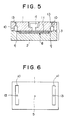
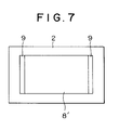
- a method of bringing the inside of the cavity into a pressurized state in the embodiment shown in Figs. 5 to 7 is to introduce an inert gas into the air reservoir spaces 10 through one or more passages 13.
- the degree of pressurization applied in the present invention is usually in the range of 1 to 20 kg/cm G, preferably 2 to 10 kg/cm G, more preferably 3 to 7 kg/cm Gauge.
- a pressurized state may be brought about at any time during the period after completion of injection of the liquid resin material up till gelation of the liquid resin material, but it is preferred to pressurize immediately after completion of injection when the viscosity of the liquid resin material is still low. Pressurization may be begun concurrently with the start of injection or during injection of the liquid resin material, but in this case, since the pressure due to flow pressure loss of the resin is given in addition to the pressure of the pressurized gas around the gate 7 in the mold 3, it is necessary to make some allowance for the injection pressure and the clamping force between the upper and lower mould pieces.
- a metal mould having a platen with a size of 1,020 mm x 510 mm and a cavity of 3 mm in depth was used.
- the mould was provided with a gate at one end of the cavity and a liquid reservoir space at the other end of the cavity.
- a metal mould having a platen with a size of 1,020 mm x 510 mm and a cavity of 3 mm in depth was used.
- the mold was provided with a liquid resin material discharge port at center of an upper surface of the cavity and a liquid reservoir space at both ends of the cavity.
- composition A A 50:50 (by weight) mixture of bisphenol F-type glycidyl ether and glycidyl methacrylate (SY Monomer G, produced by Sakamoto Yakuhin Co., Ltd.) was used for composition A.
- composition B A 106:5:1 (by weight) mixture of methyltetrahydrophthalic anhydride, 2-ethyl-4-methylimidazole and 1,1-bis(tert-butylperoxy)-3,3,5-trimethylcyclohexane (PERHEXA 3M, produced by Nippon Yushi) was used in composition B.
- the fiber reinforcement was placed in the cavity, and the top and bottom mould pieces were clamped with a clamping force of about 70 tons.
- the mould temperature was kept at 120°C for both top and bottom mould pieces.
- the mold was slanted at an angle of about 80° to the horizontal with the gate side lowermost. Then the resin materials A and B were mixed through impingement by a mixing head in an epoxy equivalent ratio of 10:8, and the mixed material was immediately injected into the cavity. The injection amount of the liquid resin material has been previously determined so that the liquid level would reach substantially the middle of the liquid reservoir space.
- the moulded product thus obtained had a very excellent state of impregnation of the liquid resin material into the fibre reinforcement and presented high transparency although it contained about 25% by volume of fibre reinforcement.
- Example 1 The procedure of Example 1 was followed except that introduction of pressurized air was omitted.
- the resulting moulded product included many cells of various sizes and assumed a generally milk-white vague colour.
- the resin-impregnated solidified glass fibers were seen exposed at some parts of the surface.
- the fibre reinforcement was placed in the cavity, and the top and bottom mould-pieces were clamped with a clamping force of about 70 tons.
- the mould temperature was kept at 120°C for both top and bottom forces.
- the resin materials A and B were mixed through impingement by a mixing head in an epoxy equivalent ratio of 10:8, and the mixed material was immediately injected into the cavity.
- the injection amount of the liquid resin material had been previously determined so that the liquid level would reach substantially to the liquid reservoir space.
- the molded product thus obtained had an excellent state of impregnation of the liquid resin material into the fiber reinforcement and presented high transparency although it contained about 25% by volume of fibre reinforcement.
Applications Claiming Priority (2)
| Application Number | Priority Date | Filing Date | Title |
|---|---|---|---|
| JP3306628A JPH05116169A (ja) | 1991-10-25 | 1991-10-25 | 繊維強化樹脂成形体の製造方法 |
| JP306628/91 | 1991-10-25 |
Publications (2)
| Publication Number | Publication Date |
|---|---|
| EP0539182A1 true EP0539182A1 (fr) | 1993-04-28 |
| EP0539182B1 EP0539182B1 (fr) | 1997-04-16 |
Family
ID=17959381
Family Applications (1)
| Application Number | Title | Priority Date | Filing Date |
|---|---|---|---|
| EP92309624A Expired - Lifetime EP0539182B1 (fr) | 1991-10-25 | 1992-10-21 | Procédé pour la fabrication d'articles moulés à partir de résines renforcées par des fibres |
Country Status (4)
| Country | Link |
|---|---|
| US (1) | US5364584A (fr) |
| EP (1) | EP0539182B1 (fr) |
| JP (1) | JPH05116169A (fr) |
| DE (1) | DE69219062T2 (fr) |
Cited By (3)
| Publication number | Priority date | Publication date | Assignee | Title |
|---|---|---|---|---|
| EP0751857A1 (fr) * | 1995-01-27 | 1997-01-08 | McDONNELL DOUGLAS HELICOPTER COMPANY | Procede de moulage de transfert de resine |
| EP0785062A2 (fr) * | 1996-01-16 | 1997-07-23 | Hudson Products Corporation | Dispositifs et procédés pour le moulage de matières plastiques |
| US5980796A (en) * | 1994-08-01 | 1999-11-09 | G. Schwartz Gmbh & Co. Kg | Process for producing molded parts by polymerization of lactams in molds |
Families Citing this family (30)
| Publication number | Priority date | Publication date | Assignee | Title |
|---|---|---|---|---|
| US5565162A (en) * | 1994-09-30 | 1996-10-15 | Composite Manufacturing & Research Inc. | Method for manufacturing a fiber reinforced composite article |
| US5914082A (en) * | 1995-11-30 | 1999-06-22 | Harrison; Donald G. | Method and apparatus for molding thermosetting polymers onto substrates |
| US5928593A (en) * | 1995-11-30 | 1999-07-27 | Harrison; Donald G. | Method and apparatus for molding thermosetting polymers onto substrates |
| US6241930B1 (en) * | 1995-11-30 | 2001-06-05 | Ubertech Texas, Inc. | Method of constructing a garment with a graphical design thereon |
| US5939004A (en) * | 1995-11-30 | 1999-08-17 | Harrison; Donald G. | Molding thermosetting polymers onto substrates |
| US6193914B1 (en) | 1995-11-30 | 2001-02-27 | Ubertech Texas, Inc. | Molding thermosetting polymers onto substrates |
| US6139787A (en) | 1996-10-24 | 2000-10-31 | Ubertech Texas, Inc. | Method for applying molded silicone design elements onto substrates |
| BE1011627A6 (nl) * | 1997-12-18 | 1999-11-09 | Debergh Jeanine | Werkwijze voor het vervaardigen van gewapende putdeksels in kunststof en gewapende putdeksels in kunststof volgens deze wijze bekomen. |
| ES2234707T5 (es) | 1999-12-07 | 2008-06-16 | The Boeing Company | Procedimiento de infusion al vacio, con doble bolsa, para fabricar un material compuesto y material compuesto asi obtenido. |
| US6565792B2 (en) * | 2001-05-11 | 2003-05-20 | Hardcore Composites | Apparatus and method for use in molding a composite structure |
| EP1415793A1 (fr) * | 2002-11-04 | 2004-05-06 | Alcan Technology & Management Ltd. | Procédé de fabrication des éléments de construction en matière plastique renforcés par des fibres |
| DE102004006074A1 (de) * | 2004-02-07 | 2005-08-25 | Hennecke Gmbh | Verfahren und Vorrichtung zur Herstellung von Polyurethan-Formteilen |
| US7849729B2 (en) | 2006-12-22 | 2010-12-14 | The Boeing Company | Leak detection in vacuum bags |
| JP5050573B2 (ja) * | 2007-03-05 | 2012-10-17 | 富士通株式会社 | 電子装置の製造方法 |
| US9770871B2 (en) | 2007-05-22 | 2017-09-26 | The Boeing Company | Method and apparatus for layup placement |
| US8568551B2 (en) * | 2007-05-22 | 2013-10-29 | The Boeing Company | Pre-patterned layup kit and method of manufacture |
| US8936695B2 (en) | 2007-07-28 | 2015-01-20 | The Boeing Company | Method for forming and applying composite layups having complex geometries |
| US8707766B2 (en) | 2010-04-21 | 2014-04-29 | The Boeing Company | Leak detection in vacuum bags |
| US8333864B2 (en) | 2008-09-30 | 2012-12-18 | The Boeing Company | Compaction of prepreg plies on composite laminate structures |
| US8916010B2 (en) * | 2007-12-07 | 2014-12-23 | The Boeing Company | Composite manufacturing method |
| US8752293B2 (en) | 2007-12-07 | 2014-06-17 | The Boeing Company | Method of fabricating structures using composite modules and structures made thereby |
| JP4825899B2 (ja) * | 2009-06-22 | 2011-11-30 | トヨタ自動車株式会社 | 繊維強化樹脂の製造方法、繊維強化樹脂の製造装置 |
| US20120114909A1 (en) * | 2010-11-10 | 2012-05-10 | Raytheon Company | Methods and apparatus for reducing voids in a molded part |
| US9387657B2 (en) | 2010-11-12 | 2016-07-12 | The Boeing Company | Method of fabricating a curved composite structure using composite prepreg tape |
| US9701067B2 (en) | 2010-11-12 | 2017-07-11 | The Boeing Company | Method of laying up prepreg plies on contoured tools using a deformable carrier film |
| US8551380B2 (en) | 2010-11-12 | 2013-10-08 | The Boeing Company | Method of laying up prepreg plies on contoured tools using a deformable carrier film |
| KR101984331B1 (ko) * | 2011-08-26 | 2019-05-30 | 바스프 에스이 | 성형물의 제조 방법 |
| WO2013095022A1 (fr) * | 2011-12-20 | 2013-06-27 | Park Jang Won | Procédé de fabrication de produits en résine synthétique thermoplastique |
| US11305498B2 (en) | 2018-12-21 | 2022-04-19 | The Boeing Company | System and method for fabricating a composite ply layup |
| US11318689B2 (en) | 2018-12-21 | 2022-05-03 | The Boeing Company | Ply transporting and compacting apparatus and method therefor |
Citations (2)
| Publication number | Priority date | Publication date | Assignee | Title |
|---|---|---|---|---|
| EP0294768A1 (fr) * | 1987-06-08 | 1988-12-14 | The Dow Chemical Company | Procédé pour fabriquer des pièces de moulage réactif par injection renforcées par un treillis |
| EP0320302A2 (fr) * | 1987-12-10 | 1989-06-14 | General Electric Company | Procédé et appareil pour fabriquer un objet en matière composite renforcée de fibres |
Family Cites Families (8)
| Publication number | Priority date | Publication date | Assignee | Title |
|---|---|---|---|---|
| US3028284A (en) * | 1953-11-24 | 1962-04-03 | John F Reeves | Molding method for plastic bodies |
| GB1024582A (en) * | 1961-07-05 | 1966-03-30 | Rodgers William | A method of manufacturing a synthetic resin moulding reinforced with fibrous material |
| US4002715A (en) * | 1972-08-14 | 1977-01-11 | Fumio Usui | Method for producing a tapered pipe of reinforced synthetic resin |
| US4353862A (en) * | 1980-05-12 | 1982-10-12 | Kaman Aerospace Corporation | Method for making sound board |
| US5023041A (en) * | 1987-12-10 | 1991-06-11 | General Electric Company | Method for making a fiber reinforced composite article |
| US5093067A (en) * | 1988-03-14 | 1992-03-03 | Allied-Signal Inc. | Injection molding of fabric reinforced elastomeric diaphragms |
| US5162092A (en) * | 1990-11-29 | 1992-11-10 | Cascade Engineering, Inc. | Gas-assisted injection molding with a carpet layer |
| US5244613A (en) * | 1993-01-21 | 1993-09-14 | Miles Inc. | Process for the production of reinforced moldings and the resultant products |
-
1991
- 1991-10-25 JP JP3306628A patent/JPH05116169A/ja active Pending
-
1992
- 1992-10-16 US US07/961,248 patent/US5364584A/en not_active Expired - Fee Related
- 1992-10-21 EP EP92309624A patent/EP0539182B1/fr not_active Expired - Lifetime
- 1992-10-21 DE DE69219062T patent/DE69219062T2/de not_active Expired - Fee Related
Patent Citations (2)
| Publication number | Priority date | Publication date | Assignee | Title |
|---|---|---|---|---|
| EP0294768A1 (fr) * | 1987-06-08 | 1988-12-14 | The Dow Chemical Company | Procédé pour fabriquer des pièces de moulage réactif par injection renforcées par un treillis |
| EP0320302A2 (fr) * | 1987-12-10 | 1989-06-14 | General Electric Company | Procédé et appareil pour fabriquer un objet en matière composite renforcée de fibres |
Cited By (6)
| Publication number | Priority date | Publication date | Assignee | Title |
|---|---|---|---|---|
| US5980796A (en) * | 1994-08-01 | 1999-11-09 | G. Schwartz Gmbh & Co. Kg | Process for producing molded parts by polymerization of lactams in molds |
| EP0751857A1 (fr) * | 1995-01-27 | 1997-01-08 | McDONNELL DOUGLAS HELICOPTER COMPANY | Procede de moulage de transfert de resine |
| EP0751857A4 (fr) * | 1995-01-27 | 1998-04-29 | Mc Donnell Douglas Helicopter | Procede de moulage de transfert de resine |
| EP0785062A2 (fr) * | 1996-01-16 | 1997-07-23 | Hudson Products Corporation | Dispositifs et procédés pour le moulage de matières plastiques |
| EP0785062A3 (fr) * | 1996-01-16 | 1998-01-28 | Hudson Products Corporation | Dispositifs et procédés pour le moulage de matières plastiques |
| CN1067628C (zh) * | 1996-01-16 | 2001-06-27 | 赫德逊产品有限公司 | 模制中空的风机叶片的方法和装置 |
Also Published As
| Publication number | Publication date |
|---|---|
| JPH05116169A (ja) | 1993-05-14 |
| EP0539182B1 (fr) | 1997-04-16 |
| US5364584A (en) | 1994-11-15 |
| DE69219062T2 (de) | 1997-07-24 |
| DE69219062D1 (de) | 1997-05-22 |
Similar Documents
| Publication | Publication Date | Title |
|---|---|---|
| EP0539182B1 (fr) | Procédé pour la fabrication d'articles moulés à partir de résines renforcées par des fibres | |
| EP0272635B1 (fr) | Procédé de moulage de plastiques renforcés par des fibres | |
| US4692291A (en) | Molding method using fast curing fiber reinforced, low viscosity thermosetting resin | |
| CA1157361A (fr) | Methode et dispositif de production de panneaux mousses | |
| EP2565019A1 (fr) | Méthode de moulage RTM | |
| JP2802430B2 (ja) | モールディング方法 | |
| EP0019149B1 (fr) | Procédé et dispositif pour le moulage | |
| CA1086912A (fr) | Procede de moulage d'un article en forme de tore | |
| JPH06210644A (ja) | 繊維強化プラスチツクの成形方法及び装置 | |
| US4091061A (en) | Method for the production of mouldings containing reinforcing fibre type filler | |
| KR950015119B1 (ko) | 섬유-보강 에폭시 매트릭스 조성물을 제조하는 방법 | |
| CN113442467B (zh) | 纤维强化树脂成型品的制造方法 | |
| JPH05116170A (ja) | Srim用成形型 | |
| US5814256A (en) | Process of producing preforms containing light weight filler particles | |
| US5609805A (en) | Process for producing a composite part by compression molding | |
| GB2232373A (en) | Moulding a reinforced article | |
| JPH05116173A (ja) | 繊維強化樹脂成形体の製造方法 | |
| JPH082543B2 (ja) | 繊維強化プラスチック成形品の成形法 | |
| JPH08108444A (ja) | 構造反応射出成形装置及び構造反応射出成形方法 | |
| GB2188636A (en) | Thermoset polyester and phenolic foams having denser outer skin | |
| JP3321819B2 (ja) | 反応射出成形用金型及びそれを用いる成形法 | |
| JPH04316811A (ja) | 複合材の成形方法 | |
| JPH09225956A (ja) | 繊維強化反応射出成形品の製造方法 | |
| JPH05116172A (ja) | 反応射出成形機 | |
| JPH0235654B2 (ja) | Senikyokapurasuchitsukususeihinnoseikeihoho |
Legal Events
| Date | Code | Title | Description |
|---|---|---|---|
| PUAI | Public reference made under article 153(3) epc to a published international application that has entered the european phase |
Free format text: ORIGINAL CODE: 0009012 |
|
| AK | Designated contracting states |
Kind code of ref document: A1 Designated state(s): DE FR GB |
|
| 17P | Request for examination filed |
Effective date: 19931019 |
|
| 17Q | First examination report despatched |
Effective date: 19941207 |
|
| RAP1 | Party data changed (applicant data changed or rights of an application transferred) |
Owner name: MITSUBISHI CHEMICAL CORPORATION |
|
| GRAG | Despatch of communication of intention to grant |
Free format text: ORIGINAL CODE: EPIDOS AGRA |
|
| GRAH | Despatch of communication of intention to grant a patent |
Free format text: ORIGINAL CODE: EPIDOS IGRA |
|
| GRAH | Despatch of communication of intention to grant a patent |
Free format text: ORIGINAL CODE: EPIDOS IGRA |
|
| GRAA | (expected) grant |
Free format text: ORIGINAL CODE: 0009210 |
|
| AK | Designated contracting states |
Kind code of ref document: B1 Designated state(s): DE FR GB |
|
| REF | Corresponds to: |
Ref document number: 69219062 Country of ref document: DE Date of ref document: 19970522 |
|
| ET | Fr: translation filed | ||
| PLBE | No opposition filed within time limit |
Free format text: ORIGINAL CODE: 0009261 |
|
| STAA | Information on the status of an ep patent application or granted ep patent |
Free format text: STATUS: NO OPPOSITION FILED WITHIN TIME LIMIT |
|
| 26N | No opposition filed | ||
| PGFP | Annual fee paid to national office [announced via postgrant information from national office to epo] |
Ref country code: FR Payment date: 19991011 Year of fee payment: 8 |
|
| PGFP | Annual fee paid to national office [announced via postgrant information from national office to epo] |
Ref country code: GB Payment date: 19991020 Year of fee payment: 8 |
|
| PGFP | Annual fee paid to national office [announced via postgrant information from national office to epo] |
Ref country code: DE Payment date: 19991022 Year of fee payment: 8 |
|
| PG25 | Lapsed in a contracting state [announced via postgrant information from national office to epo] |
Ref country code: GB Free format text: LAPSE BECAUSE OF NON-PAYMENT OF DUE FEES Effective date: 20001021 |
|
| GBPC | Gb: european patent ceased through non-payment of renewal fee |
Effective date: 20001021 |
|
| PG25 | Lapsed in a contracting state [announced via postgrant information from national office to epo] |
Ref country code: FR Free format text: LAPSE BECAUSE OF NON-PAYMENT OF DUE FEES Effective date: 20010629 |
|
| PG25 | Lapsed in a contracting state [announced via postgrant information from national office to epo] |
Ref country code: DE Free format text: LAPSE BECAUSE OF NON-PAYMENT OF DUE FEES Effective date: 20010703 |
|
| REG | Reference to a national code |
Ref country code: FR Ref legal event code: ST |