EP0538845B1 - Gerät zur Behandlung von Kontaktlinsen und Gefäss zur Behandlung von Kontaktlinsen zur Verwendung hierin - Google Patents
Gerät zur Behandlung von Kontaktlinsen und Gefäss zur Behandlung von Kontaktlinsen zur Verwendung hierin Download PDFInfo
- Publication number
- EP0538845B1 EP0538845B1 EP92118034A EP92118034A EP0538845B1 EP 0538845 B1 EP0538845 B1 EP 0538845B1 EP 92118034 A EP92118034 A EP 92118034A EP 92118034 A EP92118034 A EP 92118034A EP 0538845 B1 EP0538845 B1 EP 0538845B1
- Authority
- EP
- European Patent Office
- Prior art keywords
- treating
- contact lens
- treating vessel
- vessel
- electromagnetic induction
- Prior art date
- Legal status (The legal status is an assumption and is not a legal conclusion. Google has not performed a legal analysis and makes no representation as to the accuracy of the status listed.)
- Expired - Lifetime
Links
Images
Classifications
-
- A—HUMAN NECESSITIES
- A61—MEDICAL OR VETERINARY SCIENCE; HYGIENE
- A61L—METHODS OR APPARATUS FOR STERILISING MATERIALS OR OBJECTS IN GENERAL; DISINFECTION, STERILISATION OR DEODORISATION OF AIR; CHEMICAL ASPECTS OF BANDAGES, DRESSINGS, ABSORBENT PADS OR SURGICAL ARTICLES; MATERIALS FOR BANDAGES, DRESSINGS, ABSORBENT PADS OR SURGICAL ARTICLES
- A61L12/00—Methods or apparatus for disinfecting or sterilising contact lenses; Accessories therefor
- A61L12/02—Methods or apparatus for disinfecting or sterilising contact lenses; Accessories therefor using physical phenomena, e.g. electricity, ultrasound or ultrafiltration
-
- Y—GENERAL TAGGING OF NEW TECHNOLOGICAL DEVELOPMENTS; GENERAL TAGGING OF CROSS-SECTIONAL TECHNOLOGIES SPANNING OVER SEVERAL SECTIONS OF THE IPC; TECHNICAL SUBJECTS COVERED BY FORMER USPC CROSS-REFERENCE ART COLLECTIONS [XRACs] AND DIGESTS
- Y10—TECHNICAL SUBJECTS COVERED BY FORMER USPC
- Y10S—TECHNICAL SUBJECTS COVERED BY FORMER USPC CROSS-REFERENCE ART COLLECTIONS [XRACs] AND DIGESTS
- Y10S134/00—Cleaning and liquid contact with solids
- Y10S134/901—Contact lens
Definitions
- the present invention relates to an apparatus for treating contact lenses and a contact lens treating vessel for use therein, and more particularly to an apparatus for treating contact lenses, in which the contact lenses can be cleaned and sterilized by immersing the contact lenses in a treating solution for contact lenses and applying a direct current to the treating solution, and a contact lens treating vessel for use therein.
- a contact lens treating vessel which is used in the above-mentioned apparatus is constructed so that the treating vessel can be attached to or detached from an apparatus body and the treating vessel in which the contact lens is stored can be a portable vessel.
- the vessel has the following defects. Dust and the like are deposited over the electrodes of the treating vessel and the apparatus body, so that insufficient electrical contact is caused.
- the electrodes are worn away and insufficient electric conduction is sometimes caused.
- a leak of electricity is sometimes caused when the electrolyte solution is contacted with the electrode of the apparatus body. Therefore, the improvement of the vessel has been earnestly expected.
- An object of the present invention is to provide an apparatus for treating contact lenses, which would not generate insufficient electric conduction, a leak of electricity and the like due to insufficient electrical contact between electrodes.
- a further object of the present invention is to provide a contact lens treating vessel for use therein.
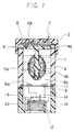
- Fig.1 shows a contact lens treating vessel of the present invention.
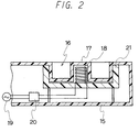
- Fig.2 shows a treating apparatus body used in an apparatus for treating contact lenses of the present invention.
- Fig. 1 is a cross-sectional view of the principal part of an embodiment of the contact lens treating vessel of the present invention.
- the numeral 1 denotes a treating vessel body.
- a support 4a of a basket 4 for accommodating and holding contact lenses 3a and 3b is provided between the treating vessel body 1 and a lid 2 which can be attached to or detached from the treating vessel body 1.
- the support 4a has some air vents 4b.
- a heat resistant resin such as polysulfone or polycarbonate, or the like can be used.
- a seal packing 5 is provided between the treating vessel body 1 and the support 4a, and a gas-permeable film 6 is provided between the support 4a and the lid 2.
- the gas-permeable film 6 has numerous fine pores through which vapor and gas can pass but liquid cannot pass.
- the lid 2 has plural air vents 7.
- a pair of electrodes 8a and 8b is provided on a bottom panel 9 of the treating vessel body 1.
- any materials usually employed can be used without any limitation.
- metals such as stainless steel, platinum, gold, copper and nickel; carbon rod; a synthetic resin on which a metal such as gold or platinum is coated by plating; an insulating material, the surface of which is coated with a paste containing a metal such as gold or platinum as a main component by a printing method and then baked; an insulating material over which the metal is vapor-deposited, and the like.
- the electrode is made of a metal such as gold or platinum, which has a small ionization tendency and a difficulty to be dissolved in the electrolyte solution, the synthetic resin on which the metal is coated by plating, the insulating material, the surface of which is coated with the paste, or the insulating material over which the metal is vapor-deposited.
- the gas-permeable film 6 usually has many fine pores having a diameter of 0.1 to 3.0 ⁇ m or so and a thickness of 75 to 700 ⁇ m or so. When the diameter of the pore is adjusted to 0.2 ⁇ m or less, pollution of the electrolyte solution can be prevented after disinfecting because microorganism and the like hardly pass through the gas-permeable film 6.
- the gas-permeable film 6 there can be cited, for instance, a fluorocarbon resin film on which a polypropylene net is laminated, a hydrophobic microbial filter, a hydrophobic microfiltration membrane made of polyethylene, polypropylene or the like, silicone film, and the like. A netlike reinforcement or the like can be attached to the gas-permeable film 6.
- the bottom panel 9 is provided between the treating vessel body 1 and the bottom body 10 through a seal packing 11.
- the electromagnetic induction coil 12 is provided under the treating vessel body 1.
- the electromagnetic induction coil 12 is connected with the electrodes 8a and 8b through a lead, and a rectifier 13 and a condenser 14 are provided between the electromagnetic induction coil 12 and the electrodes 8a and 8b.
- the electromagnetic induction coil 12 is used for generating an electric current by electromagnetic induction produced by a magnetic field which is generated from a magnet-generating coil.
- the number of turns of the electromagnetic induction coil 12 cannot be absolutely determined since the number of turns depends upon a magnetic force generated from the magnet-generating coil. It is desired that the number of turns is adjusted so that an electric power generated from the electromagnetic induction coil 12 is generally 5 to 50W, preferably 10 to 25W.
- an electric power generated from the electromagnetic induction coil 12 is generally 5 to 50W, preferably 10 to 25W.
- an electric current applied to the electrolyte solution is 0.01 to 5A, preferably 0.05 to 0.5A so that stains such as proteins which are adhered to a lens during usual wearing can be removed.
- the electric current is less than the above-mentioned range, peroxides are little generated in the electrolyte solution during the application of an electric current to the solution, thereby there is a tendency that the removal of proteins becomes insufficient.
- the electric current exceeds the above-mentioned range, the reaction becomes radical on the electrodes, thereby the electrodes are sometimes damaged although the removal of proteins are sufficient.
- the rectifier 13 is used for obtaining secondary power by rectifying secondary voltage which is generated during the application of an electric current of a primary circuit.
- the rectifier 13 there can be cited, for instance, a silicone diode and the like. Since the silicone diode has a relatively high operating frequency, rectifiers having a short reverse recovery time such as a fast recovery diode and a shottky barrier diode are preferable from the viewpoint of efficiency.
- a condenser 14 is used for producing smoothed voltage by accumulating half-wave DC voltage which is obtained by the rectifier 13.
- the condenser 14 can impart approximately constant voltage to the electrodes 8a and 8b.
- Capacity of the condenser 14 depends upon the oscillation frequency of a magnetic circuit. It is desired that the capacity is 0.1 to 100 ⁇ F or so, preferably 0.1 to 10 ⁇ F or so in consideration of the outside dimension of the condenser for accommodating the condenser in the contact lens treating vessel.
- treatment of the contact lens can be carried out without the condenser 14.
- the condenser 14 When the condenser 14 is not used, voltage which is applied to the electrodes is remarkably varied, therefore, the peak voltage and peak current at the electrodes become higher and good results in safety for electric shock, reliability of life of the electrode and the like cannot be obtained. Therefore, it is desired that the condenser is used.
- Fig. 2 is a cross-sectional view of the principal part of an embodiment of the treating apparatus body used in the apparatus for treating contact lenses of the present invention.
- the numeral 15 denotes a treating apparatus body.
- the treating apparatus body 15 is equipped with a bezel for attachment and detachment 16, which is used for installing the contact lens treating vessel, and a projection for electromagnetic induction 17.
- the projection for electromagnetic induction 17 is inserted into the inside of the electromagnetic induction coil 12.
- a magnet-generating coil 18 is provided inside the projection for electromagnetic induction 17.
- the magnet-generating coil 18 is used for generating electromagnetism and transmitting the electromagnetism to the electromagnetic induction coil 12.
- the number of turns of the magnet-generating coil 18 cannot be absolutely determined since the number of turns depends upon oscillation frequency, output, the shape of a core, voltage of power source and the like.
- the number of turns can be, for instance, 200 turns.
- Electricity is supplied from a general domestic electric source having a frequency of 50 to 60 Hz or so and an AC voltage of 100 V through a plug 19 to the magnet-generating coil 18. After the AC voltage is converted into DC voltage which is a power for a high-frequency oscillation circuit, a high-frequency current flows from the high-frequency oscillation circuit 20.
- the frequency of the high-frequency current is 100 Hz to 1MHz, preferably 1 KHz to 100 KHz or so.
- a ferrite core is provided inside the magnet-generating coil 18.
- an E-type ferrite core 21 is used.
- the E-type ferrite core 21 is also used as a ferrite core of the electromagnetic induction coil 12.
- the apparatus for treating contact lenses of the present invention has an electromagnetic induction coil and a magnet-generating coil in the contact lens treating vessel and the treating apparatus body, respectively. Therefore, when the apparatus is made of, for instance, a synthetic resin or the like so that water and the like would not invade into the apparatus, that a liquidtight state would be maintained and that the inside of the apparatus is electrically insulated from outside thereof, there is no possibility of causing the leak of electricity and the like.
- the apparatus for treating contact lenses of the present invention entirely has no conventional problem such as insufficient contact of an electrode of the contact lens treating vessel with an electrode of the treating apparatus body and has excellent usability.
- the apparatus for treating contact lenses and the contact lens treating vessel for use therein, of the present invention are more specifically described and explained by means of the following Example.
- a contact lens treating vessel shown in Fig. 1 As a contact lens treating vessel, a contact lens treating vessel shown in Fig. 1 was used.
- a bottom body 10 was equipped with an installation portion 22 for inserting a projection for electromagnetic induction 17 of a treating apparatus body 15 shown in Fig. 2.
- the installation portion 22 having a concavity was formed so that the inside diameter and the depth of the installation portion 22 were 13 mm and 11 mm, respectively.
- An electromagnetic induction coil 12 having an outside diameter of 18 mm and the number of turns of 120 turns was formed inside the bottom body 10 so that the coil was wound on the installation portion 22.
- One end of the electromagnetic induction coil 12 was connected to an electrode 8a and one end of a condenser 14 having a capacity of 10 ⁇ F through a diode which was a rectifier 13.
- Another end of the electromagnetic induction coil 12 was connected to another end of the condenser 14 and an electrode 8b.
- the electromagnetic induction coil 12, diode 13, condenser 14, electrodes 8a and 8b were connected with leads as shown in Fig. 1.
- the electrodes 8a and 8b were fixed on a bottom panel 9.
- an ABS resin panel was used as the bottom panel 9.
- platinum electrodes having a diameter of 2.7 mm and a thickness of 0.07 mm were used, respectively.
- the treating vessel body 1 and the bottom body 10 were made of a transparent polycarbonate and an ABS resin, respectively.
- the outside diameter of each of the treating vessel body 1 and the bottom body 10 was adjusted to 25 mm, respectively.
- an electrolyte solution 5.0 ml of an aqueous solution containing 1.3 % by weight of boric acid, 0.06 % by weight of borax and 0.44 % by weight of sodium citrate was used, and the aqueous solution was poured into the treating vessel body 1.
- Soft contact lenses 3a and 3b which were commercially available from Menicon Co., Ltd., under the trade name of MENICON SOFT MA were put in a basket 4 made of polycarbonate. Then, a gas-permeable film 6 made of a fluorocarbon resin was provided between a support 4a of the basket 4 and a lid 2.
- the lid 2 was put on the top of the treating vessel body 1 through the seal packing 5 made of a silicone rubber, and the lid 2 and the treating vessel body 1, which had screw threads, were engaged.
- a treating apparatus body 15 As a treating apparatus body 15, a treating apparatus body shown in Fig. 2 was used.
- a bezel for attachment and detachment 16 having an inside circuit diameter of 13 mm, an outside circuit diameter of 25 mm and a depth of 11 mm was provided around the projection for electromagnetic induction 17 of the treating apparatus body 15.
- the magnet-generating coil 18 was connected through a lead wire with a high frequency generating circuit 20 by which a current having a frequency of 60 Hz could be converted into a current having a frequency of 7 KHz.
- the high frequency generating circuit 20 was connected to a general domestic AC supply of 100 V through a plug 19.
- the projection for electromagnetic induction 17 was inserted into the inside of the installation portion 22 of the contact lens treating vessel.
- a treating solution which doubles as, for instance, an electrolyte solution can be directly heated with an aid of electrical resistance of the treating solution, by directly applying electricity to the treating solution. Therefore, the temperature of the solution can be rapidly increased, and a period of time for disinfecting can be made shorter than the period of time for disinfecting by using a conventional apparatus for heating the treating solution from outside.
- any electrically connecting points of the treating apparatus body and the treating vessel are not exposed. Therefore, insufficient electrical contact is not caused by stains of the connecting points, or the connecting points are not worn away by the repeat of attachment or detachment of the treating vessel and thereby there is no possibility such that an electric current is not sufficiently applied to the solution. Furthermore, since a short-circuit is not caused by the solution or the like when the solution is spilt during the treatment of a contact lens, the apparatus is excellent in safety and handling.
Landscapes
- Health & Medical Sciences (AREA)
- Epidemiology (AREA)
- Life Sciences & Earth Sciences (AREA)
- Animal Behavior & Ethology (AREA)
- General Health & Medical Sciences (AREA)
- Public Health (AREA)
- Veterinary Medicine (AREA)
- Eyeglasses (AREA)
- Apparatus For Disinfection Or Sterilisation (AREA)
- Water Treatment By Electricity Or Magnetism (AREA)
Claims (14)
- Gerät zur Behandlung von Kontaktlinsen mit einem Behandlungsgerät (15) für die Zufuhr von elektrischer Energie und mit einem Gefäß (1) zur Behandlung von Kontaktlinsen, welches an das Behandlungsgerät angeschlossen oder von ihm abgenommen werden kann, und bei dem dieses Behandlungsgerät mit einer Magnetspule (18) ausgerüstet ist, und das Gefäß zur Behandlung von Kontaktlinsen mit einer elektromagnetischen Induktionsspule (12) ausgerüstet ist.
- Gerät zur Behandlung von Kontaktlinsen nach Anspruch 1,
dadurch gekennzeichnet, daß
die Magnetspule gegen das Gefäß für die Behandlung von Kontaktlinsen elektrisch isoliert ist. - Gerät zur Behandlung von Kontaktlinsen nach Anspruch 1,
dadurch gekennzeichnet, daß
das Behandlungsgerät einen Hochfrequenzschwingungskreis (20) aufweist, welcher mit der Magnetspule verbunden ist. - Gerät zur Behandlung von Kontaktlinsen nach Anspruch 1,
dadurch gekennzeichnet, daß
das Behandlungsgerät eine Anfasung (16) für die Befestigung und Ablösung des Gefässes für die Behandlung von Kontaktlinsen, sowie einen Vorsprung für die elektromagnetische Induktion (17) aufweist. - Gerät zur Behandlung von Kontaktlinsen nach Anspruch 1,
dadurch gekennzeichnet, daß
die Magnetspule in dem Vorsprung für die elektromagnetische Induktion angeordnet ist. - Gerät zur Behandlung von Kontaktlinsen nach Anspruch 1,
dadurch gekennzeichnet, daß
in der Magnetspule ein Eisenkern (21) angeordnet ist. - Gerät zur Behandlung von Kontaktlinsen nach Anspruch 1,
dadurch gekennzeichnet, daß
dieses Gerät mit einer elektromagnetischen Induktionsspule und einem Gleichrichter (13) für die Umwandlung eines Wechselstroms in einen Gleichstrom ausgerüstet ist. - Gerät zur Behandlung von Kontaktlinsen nach Anspruch 7,
dadurch gekennzeichnet, daß
es mit einem Kondensator (14) ausgerüstet ist. - Gerät zur Behandlung von Kontaktlinsen nach Anspruch 7,
dadurch gekennzeichnet, daß
darin ein Korb (4) aus einem wärmefesten Harz vorgesehen ist. - Gerät zur Behandlung von Kontaktlinsen nach Anspruch 7,
dadurch gekennzeichnet, daß
an der Oberseite des Behandlungsgerätes eine mit Entlüftungsöffnungen (7) versehene Abdeckung (2) vorgesehen ist. - Gerät zur Behandlung von Kontaktlinsen nach Anspruch 7,
dadurch gekennzeichnet, daß
zwischen der Halterung (4a) und der Abdeckung eine gasdurchlässige Folie (6) vorgesehen ist, welche nicht von einer Flüssigkeit durchdrungen werden kann. - Gerät zur Behandlung von Kontaktlinsen nach Anspruch 11,
dadurch gekennzeichnet, daß
die gasdurchlässige Folie einen Porendurchmesser von 0,1 bis 3,0 µm hat. - Gerät zur Behandlung von Kontaktlinsen nach Anspruch 11,
dadurch gekennzeichnet, daß
die gasdurchlässige Folie aus einer Folie aus einem Fluorkohlenstoffharz besteht, auf die ein Polypropylennetz, ein wasserabweisender mikrobieller Filter, eine wasserabweisende Mikrofiltermembrane oder eine Siliconfolie laminiert ist. - Gerät zur Behandlung von Kontaktlinsen nach Anspruch 8,
dadurch gekennzeichnet, daß
die Kapazität des Kondensators 0,1 bis 100 µF beträgt.
Applications Claiming Priority (2)
| Application Number | Priority Date | Filing Date | Title |
|---|---|---|---|
| JP279838/91 | 1991-10-25 | ||
| JP3279838A JPH05115536A (ja) | 1991-10-25 | 1991-10-25 | コンタクトレンズ用処理装置およびそれに用いるコンタクトレンズ処理容器 |
Publications (2)
| Publication Number | Publication Date |
|---|---|
| EP0538845A1 EP0538845A1 (de) | 1993-04-28 |
| EP0538845B1 true EP0538845B1 (de) | 1998-01-28 |
Family
ID=17616635
Family Applications (1)
| Application Number | Title | Priority Date | Filing Date |
|---|---|---|---|
| EP92118034A Expired - Lifetime EP0538845B1 (de) | 1991-10-25 | 1992-10-22 | Gerät zur Behandlung von Kontaktlinsen und Gefäss zur Behandlung von Kontaktlinsen zur Verwendung hierin |
Country Status (5)
| Country | Link |
|---|---|
| US (1) | US5283053A (de) |
| EP (1) | EP0538845B1 (de) |
| JP (1) | JPH05115536A (de) |
| AU (1) | AU658101B2 (de) |
| DE (1) | DE69224260T2 (de) |
Families Citing this family (9)
| Publication number | Priority date | Publication date | Assignee | Title |
|---|---|---|---|---|
| US6495100B1 (en) * | 1996-04-04 | 2002-12-17 | Ethicon, Inc. | Method for sterilizing devices in a container |
| US6000534A (en) * | 1996-08-16 | 1999-12-14 | Allergan Sales, Inc. | Contact lens disinfecting device and disinfection system |
| US5876513A (en) * | 1997-12-01 | 1999-03-02 | Frankson; Jon | Method and kit for cleaning jewelry and other small parts |
| AU2003259290A1 (en) * | 2002-07-29 | 2004-02-16 | Evanite Fiber Corporation | Glass compositions |
| GB0324058D0 (en) * | 2003-10-14 | 2003-11-19 | Exeter Antioxidant Therapeutic | Decontamination,disinfection or sterilization method and apparatus |
| CA2609913A1 (en) * | 2005-04-26 | 2006-11-02 | Dolki Korea Ltd. | Portable contact lens cleansing apparatus and cleaning method of contact lens |
| CN103433234B (zh) * | 2013-09-02 | 2016-08-10 | 杭州视亨光电有限公司 | 一种低压直流电磁脉冲式隐形眼镜专用自动清洗仪 |
| US9532632B2 (en) | 2015-05-08 | 2017-01-03 | Better Vision Solutions LLC | Pressure-venting container for disinfection and storage of contact lenses |
| KR102295562B1 (ko) * | 2019-10-08 | 2021-08-27 | 강상호 | 살균기능을 갖는 콘텍트렌즈 보관장치 |
Family Cites Families (9)
| Publication number | Priority date | Publication date | Assignee | Title |
|---|---|---|---|---|
| DE3207436A1 (de) * | 1982-02-27 | 1983-09-08 | Franz Klaus Union Armaturen, Pumpen Gmbh & Co, 4630 Bochum | Geraet und aggregat zur erwaermung eines stroemenden mediums |
| US4697605A (en) * | 1984-08-29 | 1987-10-06 | Smc Metal Tech Co., Ltd. | Contact lens cleaning apparatus |
| DE3622391A1 (de) * | 1986-07-03 | 1988-01-14 | Henkel Kgaa | Verfahren und vorrichtung zur kontaktlinsenpflege |
| DE3639099A1 (de) * | 1986-11-15 | 1988-05-26 | Henkel Kgaa | Vorrichtung zur pflegebehandlung von kontaktlinsen |
| DE3639101A1 (de) * | 1986-11-15 | 1988-05-19 | Henkel Kgaa | Vorrichtung zur pflegebehandlung von kontaktlinsen |
| GB8716886D0 (en) * | 1987-07-17 | 1987-08-26 | Ifejika C P | Cleaning apparatus |
| CH677541A5 (de) * | 1989-04-05 | 1991-05-31 | Edwin Zimmerli | |
| US5105841A (en) * | 1990-03-31 | 1992-04-21 | Aisin Seiki Kabushiki Kaisha | Cleaning device for contact lenses |
| US5101086A (en) * | 1990-10-25 | 1992-03-31 | Hydro-Quebec | Electromagnetic inductor with ferrite core for heating electrically conducting material |
-
1991
- 1991-10-25 JP JP3279838A patent/JPH05115536A/ja active Pending
-
1992
- 1992-10-21 US US07/963,981 patent/US5283053A/en not_active Expired - Fee Related
- 1992-10-22 EP EP92118034A patent/EP0538845B1/de not_active Expired - Lifetime
- 1992-10-22 DE DE69224260T patent/DE69224260T2/de not_active Expired - Fee Related
- 1992-10-22 AU AU27264/92A patent/AU658101B2/en not_active Ceased
Also Published As
| Publication number | Publication date |
|---|---|
| AU658101B2 (en) | 1995-03-30 |
| DE69224260D1 (de) | 1998-03-05 |
| JPH05115536A (ja) | 1993-05-14 |
| AU2726492A (en) | 1993-04-29 |
| DE69224260T2 (de) | 1998-08-27 |
| US5283053A (en) | 1994-02-01 |
| EP0538845A1 (de) | 1993-04-28 |
Similar Documents
| Publication | Publication Date | Title |
|---|---|---|
| US4236992A (en) | High voltage electrolytic cell | |
| US4316787A (en) | High voltage electrolytic cell | |
| EP0538845A1 (de) | Gerät zur Behandlung von Kontaktlinsen und Gefäss zur Behandlung von Kontaktlinsen zur Verwendung hierin | |
| US4202740A (en) | Apparatus and method for disinfecting objects | |
| WO1998011942A1 (en) | Enhanced transcutaneous recharging system for battery powered implantable medical device | |
| HUT48693A (en) | Equipment for the electrochemical cleaning of materials, mainly wires, applied during welding | |
| US6821403B1 (en) | Method and device for cleaning and disinfecting treatment of water | |
| CA2207376A1 (en) | Electrolytic test machine | |
| US1902390A (en) | wormley | |
| EP1597815A2 (de) | Wandlerschaltung, system und verfahren zur durchführung eines elektrochemischen prozesses | |
| RU2057546C1 (ru) | Контейнер для стерилизации медицинского металлического инструмента | |
| WO2003084600A2 (en) | Sterile disposable internal defibrillation paddles | |
| JPS644500A (en) | Method for electrolyzing metallic material surface | |
| JPH11266582A5 (de) | ||
| CN209899113U (zh) | 一种制备富氢水或臭氧水的制备装置 | |
| KR20100084735A (ko) | 이동형 수산기 발생장치 | |
| JPS602700A (ja) | 電解式脱スケ−ル用電極布 | |
| JP2023153464A (ja) | 美顔器 | |
| CN209803587U (zh) | 一种焊机温控装置 | |
| EP0613691A4 (de) | Vorrichtung zum sterilisieren von weichen kontaktlinsen. | |
| CN117906286A (zh) | 蒸汽发生装置、衣物处理设备及控制方法 | |
| EP0456436A2 (de) | Pipettenladungssystem | |
| CA2519519A1 (en) | Device and the parts thereof for producing electrodeposited dental shaped pieces | |
| RU94023296A (ru) | Способ оксидирования изделий катодно-анодными микроразрядами | |
| KR101555747B1 (ko) | 전기 세척장치 |
Legal Events
| Date | Code | Title | Description |
|---|---|---|---|
| PUAI | Public reference made under article 153(3) epc to a published international application that has entered the european phase |
Free format text: ORIGINAL CODE: 0009012 |
|
| AK | Designated contracting states |
Kind code of ref document: A1 Designated state(s): DE FR GB |
|
| 17P | Request for examination filed |
Effective date: 19930901 |
|
| GRAG | Despatch of communication of intention to grant |
Free format text: ORIGINAL CODE: EPIDOS AGRA |
|
| 17Q | First examination report despatched |
Effective date: 19970314 |
|
| GRAG | Despatch of communication of intention to grant |
Free format text: ORIGINAL CODE: EPIDOS AGRA |
|
| GRAG | Despatch of communication of intention to grant |
Free format text: ORIGINAL CODE: EPIDOS AGRA |
|
| GRAH | Despatch of communication of intention to grant a patent |
Free format text: ORIGINAL CODE: EPIDOS IGRA |
|
| GRAH | Despatch of communication of intention to grant a patent |
Free format text: ORIGINAL CODE: EPIDOS IGRA |
|
| GRAA | (expected) grant |
Free format text: ORIGINAL CODE: 0009210 |
|
| AK | Designated contracting states |
Kind code of ref document: B1 Designated state(s): DE FR GB |
|
| REF | Corresponds to: |
Ref document number: 69224260 Country of ref document: DE Date of ref document: 19980305 |
|
| ET | Fr: translation filed | ||
| PG25 | Lapsed in a contracting state [announced via postgrant information from national office to epo] |
Ref country code: GB Free format text: LAPSE BECAUSE OF NON-PAYMENT OF DUE FEES Effective date: 19981022 |
|
| PLBE | No opposition filed within time limit |
Free format text: ORIGINAL CODE: 0009261 |
|
| STAA | Information on the status of an ep patent application or granted ep patent |
Free format text: STATUS: NO OPPOSITION FILED WITHIN TIME LIMIT |
|
| 26N | No opposition filed | ||
| GBPC | Gb: european patent ceased through non-payment of renewal fee |
Effective date: 19981022 |
|
| PG25 | Lapsed in a contracting state [announced via postgrant information from national office to epo] |
Ref country code: FR Free format text: LAPSE BECAUSE OF NON-PAYMENT OF DUE FEES Effective date: 19990630 |
|
| REG | Reference to a national code |
Ref country code: FR Ref legal event code: ST |
|
| PG25 | Lapsed in a contracting state [announced via postgrant information from national office to epo] |
Ref country code: DE Free format text: LAPSE BECAUSE OF NON-PAYMENT OF DUE FEES Effective date: 19990803 |