EP0538727B1 - Reflektor für eine Leuchte - Google Patents
Reflektor für eine Leuchte Download PDFInfo
- Publication number
- EP0538727B1 EP0538727B1 EP92117550A EP92117550A EP0538727B1 EP 0538727 B1 EP0538727 B1 EP 0538727B1 EP 92117550 A EP92117550 A EP 92117550A EP 92117550 A EP92117550 A EP 92117550A EP 0538727 B1 EP0538727 B1 EP 0538727B1
- Authority
- EP
- European Patent Office
- Prior art keywords
- reflector
- foil
- metal sheet
- reflector according
- perforated metal
- Prior art date
- Legal status (The legal status is an assumption and is not a legal conclusion. Google has not performed a legal analysis and makes no representation as to the accuracy of the status listed.)
- Expired - Lifetime
Links
- 239000011888 foil Substances 0.000 claims abstract description 8
- 239000000463 material Substances 0.000 claims description 8
- 239000002184 metal Substances 0.000 claims description 7
- 239000011022 opal Substances 0.000 abstract description 2
- 229910052736 halogen Inorganic materials 0.000 abstract 1
- 150000002367 halogens Chemical class 0.000 abstract 1
- 238000004519 manufacturing process Methods 0.000 description 8
- 239000004753 textile Substances 0.000 description 4
- 230000000694 effects Effects 0.000 description 2
- 229920003229 poly(methyl methacrylate) Polymers 0.000 description 2
- 239000004926 polymethyl methacrylate Substances 0.000 description 2
- 239000000853 adhesive Substances 0.000 description 1
- 230000001070 adhesive effect Effects 0.000 description 1
- 238000000071 blow moulding Methods 0.000 description 1
- 238000001125 extrusion Methods 0.000 description 1
- 230000004313 glare Effects 0.000 description 1
- 239000003292 glue Substances 0.000 description 1
- 230000001795 light effect Effects 0.000 description 1
- 229920003023 plastic Polymers 0.000 description 1
- 239000004033 plastic Substances 0.000 description 1
Images

Classifications
-
- F—MECHANICAL ENGINEERING; LIGHTING; HEATING; WEAPONS; BLASTING
- F21—LIGHTING
- F21V—FUNCTIONAL FEATURES OR DETAILS OF LIGHTING DEVICES OR SYSTEMS THEREOF; STRUCTURAL COMBINATIONS OF LIGHTING DEVICES WITH OTHER ARTICLES, NOT OTHERWISE PROVIDED FOR
- F21V13/00—Producing particular characteristics or distribution of the light emitted by means of a combination of elements specified in two or more of main groups F21V1/00 - F21V11/00
- F21V13/12—Combinations of only three kinds of elements
-
- F—MECHANICAL ENGINEERING; LIGHTING; HEATING; WEAPONS; BLASTING
- F21—LIGHTING
- F21V—FUNCTIONAL FEATURES OR DETAILS OF LIGHTING DEVICES OR SYSTEMS THEREOF; STRUCTURAL COMBINATIONS OF LIGHTING DEVICES WITH OTHER ARTICLES, NOT OTHERWISE PROVIDED FOR
- F21V11/00—Screens not covered by groups F21V1/00, F21V3/00, F21V7/00 or F21V9/00
- F21V11/08—Screens not covered by groups F21V1/00, F21V3/00, F21V7/00 or F21V9/00 using diaphragms containing one or more apertures
- F21V11/14—Screens not covered by groups F21V1/00, F21V3/00, F21V7/00 or F21V9/00 using diaphragms containing one or more apertures with many small apertures
-
- F—MECHANICAL ENGINEERING; LIGHTING; HEATING; WEAPONS; BLASTING
- F21—LIGHTING
- F21V—FUNCTIONAL FEATURES OR DETAILS OF LIGHTING DEVICES OR SYSTEMS THEREOF; STRUCTURAL COMBINATIONS OF LIGHTING DEVICES WITH OTHER ARTICLES, NOT OTHERWISE PROVIDED FOR
- F21V7/00—Reflectors for light sources
- F21V7/0008—Reflectors for light sources providing for indirect lighting
- F21V7/0016—Reflectors for light sources providing for indirect lighting on lighting devices that also provide for direct lighting, e.g. by means of independent light sources, by splitting of the light beam, by switching between both lighting modes
-
- F—MECHANICAL ENGINEERING; LIGHTING; HEATING; WEAPONS; BLASTING
- F21—LIGHTING
- F21V—FUNCTIONAL FEATURES OR DETAILS OF LIGHTING DEVICES OR SYSTEMS THEREOF; STRUCTURAL COMBINATIONS OF LIGHTING DEVICES WITH OTHER ARTICLES, NOT OTHERWISE PROVIDED FOR
- F21V7/00—Reflectors for light sources
- F21V7/005—Reflectors for light sources with an elongated shape to cooperate with linear light sources
-
- F—MECHANICAL ENGINEERING; LIGHTING; HEATING; WEAPONS; BLASTING
- F21—LIGHTING
- F21S—NON-PORTABLE LIGHTING DEVICES; SYSTEMS THEREOF; VEHICLE LIGHTING DEVICES SPECIALLY ADAPTED FOR VEHICLE EXTERIORS
- F21S8/00—Lighting devices intended for fixed installation
- F21S8/02—Lighting devices intended for fixed installation of recess-mounted type, e.g. downlighters
Definitions
- the invention relates to a reflector specified in the preamble of claim 1.
- Such a reflector is known from GB-A-2 215 447, which will be discussed in more detail below.
- Reflectors for luminaires with elongated lamps such as a fluorescent lamp, are usually arranged below the lamp with respect to the lamp, they are basket-shaped or arched and made of perforated sheet metal.
- Such reflectors at least partially cover the lamp of the lamp and thus prevent an observer from seeing the lamp directly and being blinded thereby.
- the perforated plate alone does not guarantee complete glare protection. Under unfavorable circumstances, the viewer can partially see the lamp through the openings in the perforated plate. That is why a translucent, opal or milky white half-shell is inserted on the inside of the basket.
- the reflector just described is often used in combination with other reflectors mounted above the lamp. These reflectors are usually painted white. In order to achieve the most pleasant lighting effect of the lamp, efforts are made to make the luminance on all light-emitting surfaces of the lamp approximately the same.
- the half-shell must be about 3 mm thick for manufacturing reasons, the losses are so high that none are so high Luminance as can be achieved with the other reflectors.
- the production of the half shells is very complex.
- the half-shells are manufactured using blow molding machines by hot forming.
- the side edges have to be reworked after the deformation.
- the half-shells are extruded for large quantities.
- the side edges do not have to be reworked during extrusion, but this type of production requires high tool investments.
- the reflector known from GB-A-2 215 447 mentioned at the outset consists of a perforated plate, is provided on the inside with a textile material and is used to emit only so much diffuse light downwards that approximately the same luminance is achieved as with an illuminated ceiling .
- Textile materials transmit relatively little light, are generally expensive, and fade over time under the action of UV light.
- the textile material since the textile material is attached to the inside of the reflector, it can only be attached or removed when the lamp is disassembled.
- the object of the invention is to provide a reflector of the type specified in the preamble of patent claim 1 in such a way that it emits brighter light, is less expensive to manufacture and retains its luminous properties longer and that the translucent material can be changed more easily.
- a film instead of a textile material, let alone a half-shell, simplifies the manufacture of such a reflector considerably.
- the preferably 0.5 mm thick film is cut to the desired length and width and then only needs to be fixed to the perforated plate. This can be done both inside and outside on the perforated plate, so that there are design options.
- the production of reflectors of different sizes is possible without great effort - only the dimensions of the cut need to be changed. If a basket-like reflector is used instead of an arcuate reflector, it may be necessary under certain circumstances that the film has to be bent.
- the film is advantageously held in bends of the perforated plate or by holding elements, which ensure that the film rests on the inside and / or outside of the perforated plate. It is also possible to glue the film to the perforated plate (claims 2 and 3).
- the transparency of the reflector is increased by using a film while the number and size of the holes in the perforated plate remain the same. It is thereby achieved that the luminance on all light-emitting surfaces of the lamp can be chosen to be approximately the same size. This creates a particularly friendly indoor climate, the light effect of the lamp is perceived by the viewer as pleasant.
- Claims 4 and 5 describe advantageous refinements of the film, which teach claims 6 to 8, how a lamp with the reflector according to the invention must be designed to achieve a pleasant lighting effect.
- the invention is described by way of example with reference to FIGS. 1 to 4 on a recessed ceiling light, the reflector according to the invention of course also being able to be used in other lights.
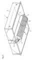
- Fig. 1 shows a lamp with a reflector according to the invention, arcuate in cross section in the installed state with an inserted lamp.
- Fig. 2 shows the same lamp, with the reflectors being particularly emphasized.
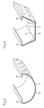
- FIG. 3 shows a reflector according to the invention.
- FIG. 4 shows a reflector according to the invention which is designed differently from FIG. 3, the film having been bent.
- FIG. 1 shows how a lamp 1 is installed in a conventional grid ceiling.
- the luminaire 1 is held by mounting rails 9 just like ceiling elements 8.
- a lamp 5 is inserted into a socket 7, electrical connection lines and operating devices not being shown for the sake of simplicity were.
- the lamp 5 is covered by a partially translucent reflector 4.
- This reflector 4 is shown partly in section.
- the reflector 4 consists of a perforated plate 10 and an inner film 11. This film 11 is preferably 0.5 mm thick, translucent and milky white.
- the lamp 1 is shown without electrical components.
- the reflector 4 is connected via holding elements 3, 3 'with screw bolts 13 to a lamp housing 6. Instead of screw connections, riveted, welded or adhesive connections can also be selected.
- the lamp housing 6 there are two further reflectors 2, 2 '. These reflectors are painted white and have the task of emitting light that comes directly from the lamp or indirectly from the reflector from the luminaire.
- the film 11 can also be attached outside the perforated plate 10.
- the holding of the film then preferably take over the holding elements 3, 3 '.
- the film 11 can be glued to the perforated plate 10.
- FIG. 3 shows a preferred embodiment of the reflector 4 with perforated sheet and foil, the illustration not being to scale and the perforation only being indicated.
- the film 11 is held by the perforated plate 10 with bends 12, 12 '.
- the film is installed in a simple manner. It only needs to be inserted under the bend 12 or 12 'on one side and then pressed down. The film is then snapped under the opposite bend 12 'or 12. It is also possible to insert the film laterally. As a result of the internal stress, the film lies fully against the perforated plate over the entire area. No further fastenings are necessary.
- the thickness of the film must be chosen so that the desired luminance can be achieved, whereby the film must not be too thick so that it lies exactly against the perforated plate.
- UV-resistant PMMA polymethyl methacrylate
- the film must be UV-resistant, because discharge lamps emit a small amount of UV light and plastics can become brittle when exposed to UV.
- the number and size of the holes in the perforated plate 10 are of course also responsible for the height of the luminance on the reflector 4.
- a perforated plate with holes whose area is 0.7 to 1.8 mm 2 and which are arranged at a distance from the center of one hole to the center of an adjacent hole of approximately 1.5 to 3.5 mm is preferably used.
- FIG. 4 shows a basket-like reflector, the illustration not being to scale and the holes - as in FIG. 3 - only being indicated. So that the film lies against the perforated plate over the entire area, the film was kinked in the region of the edges 14, 14 ', it being pointed out that it is not absolutely necessary that the film always lies against the perforated plate. If the film is not kinked, then this rests on the perforated plate in the manner of the dashed line 15.
Landscapes
- Engineering & Computer Science (AREA)
- General Engineering & Computer Science (AREA)
- Securing Globes, Refractors, Reflectors Or The Like (AREA)
- Non-Portable Lighting Devices Or Systems Thereof (AREA)
- Vessels And Coating Films For Discharge Lamps (AREA)
Description
- Die Erfindung bezieht sich auf einen Reflektor der im Oberbegriff des Patentanspruchs 1 angegebenen Art.
- Ein solcher Reflektor ist aus der GB-A-2 215 447 bekannt, auf die weiter unten noch näher eingegangen wird.
- Reflektoren für Leuchten mit langgestreckten Leuchtmitteln, wie z.B einer Leuchtstofflampe, sind meist bezüglich der Lampe unter dieser angeordnet, sie sind korbartig bzw. bogenförmig ausgebildet und aus Lochblech gefertigt.
- Solche Reflektoren überdecken zumindest teilweise die Lampe der Leuchte und verhindern damit, daß ein Betrachter direkt die Lampe sehen kann und dadurch geblendet wird. Das Lochblech allein gewährleistet noch keinen vollkommenen Blendschutz. Durch die Öffnungen im Lochblech kann der Betrachter unter ungünstigen Umständen teilweise die Lampe sehen. Darum ist an der Innenseite des Korbes eine lichtdurchlässige, opale od. milchig weiße Halbschale eingelegt.
- Der gerade beschriebene Reflektor wird häufig in Kombination mit bezüglich der Lampe über dieser montierten, weiteren Reflektoren verwendet. Diese Reflektoren sind meist weiß lackiert. Um eine möglichst angenehme Lichtwirkung der Leuchte zu erzielen, ist man bestrebt, die Leuchtdichte an allen lichtabstrahlenden Flächen der Leuchte etwa gleich groß zu machen.
- Da aus fertigungstechnischen Gründen die Halbschale etwa 3 mm dick sein muß, sind die Verluste so hoch, daß keine so hohe Leuchtdichte wie bei den weiteren Reflektoren erreicht werden kann.
- Die Herstellung der Halbschalen ist sehr aufwendig. Für kleinere Stückzahlen erfolgt die Fertigung der Halbschalen mit Blasformmaschinen durch Warmverformen. Hierbei müssen nach erfolgter Verformung die Seitenkanten nachbearbeitet werden. Bei hohen Stückzahlen werden die Halbschalen extrudiert. Die Seitenkanten müssen beim Extrudieren zwar nicht nachbearbeitet werden, aber diese Art der Fertigung bedingt hohe Werkzeuginvestitionen.
- Wird die Größe des Reflektors geändert, so müssen die Werkzeuge und Formen unabhängig von der Art der Herstellung geändert werden, was sehr kostenintensiv ist.
- Der aus der eingangs erwähnten GB-A-2 215 447 bekannte Reflektor besteht aus einem Lochblech, ist innen mit einem Textilmaterial versehen und dient dazu, nur soviel diffuses Licht nach unten abzustrahlen, daß in etwa die gleiche Leuchtdichte wie bei einer angestrahlten Decke erreicht wird. Textilmaterialien lassen relativ wenig Licht durch, sind im allgemeinen teuer und bleichen unter Wirkung von UV-Licht mit der Zeit aus. Außerdem kann das Textilmaterial, da es innen am Reflektor angebracht ist, nur bei zerlegter Leuchte angebracht oder entfernt werden.
- Aufgabe der Erfindung ist es, einen Reflektor der im Oberbegriff des Patentanspruchs 1 angegebenen Art so auszubilden, daß er heller abstrahlt, kostengünstiger herzustellen ist und länger seine Leuchteigenschaften behält und daß das lichtdurchlässige Material leichter gewechselt werden kann.
- Diese Aufgabe ist erfindungsgemäß durch die im Patentanspruch 1 angegebenen Merkmale gelöst.
- Dadurch wird vorteilhafterweise erreicht, daß die Herstellung eines derartigen Reflektors verbilligt wird.
- Durch die Verwendung einer Folie anstelle eines Textilmaterials geschweige denn einer Halbschale vereinfacht sich die Herstellung eines derartigen Reflektors ganz wesentlich. Die vorzugsweise 0,5 mm dicke Folie wird auf die gewünschte Länge und Breite zugeschnitten und braucht dann nur noch am Lochblech fixiert werden. Dies kann sowohl innen als auch außen am Lochblech geschehen, so daß designerische Gestaltungsmöglichheiten gegeben sind. Die Herstellung verschieden großer Reflektoren ist ohne großen Aufwand möglich - es müssen nur die Abmessungen des Zuschnitts geändert werden. Wird anstelle eines bogenförmigen Reflektors ein korbartiger verwendet, dann kann es unter Umständen notwendig sein, daß die Folie geknickt werden muß.
- Vorteilhaft wird die Folie in Umbiegungen des Lochblechs oder von Halteelementen gehalten, die dafür sorgen, daß die Folie innen und/oder außen am Lochblech anliegt. Ebenso ist es möglich, die Folie auf das Lochblech zu kleben (Anspruch 2 und 3).
- Außerdem wird durch Verwendung einer Folie die Lichtdurchlässigkeit des Reflektors bei gleichbleibender Anzahl und Größe der Löcher im Lochblech erhöht. Dadurch wird erreicht, daß die Leuchtdichte an allen lichtabstrahlenden Flächen der Leuchte etwa gleich groß gewählt werden kann. Dies schafft ein besonders freundliches Raumklima, die Lichtwirkung der Leuchte wird vom Betrachter als angenehm empfunden.
- Die Ansprüche 4 und 5 beschreiben vorteilhafte Ausgestaltungen der Folie, die Ansprüche 6 bis 8 lehren, wie eine Leuchte mit dem erfindungsgemäßen Reflektor ausgeführt werden muß, um eine angenehme Lichtwirkung zu erzielen.
- Die Erfindung wird anhand der Figuren 1 bis 4 beispielhaft an einer Deckeneinbauleuchte beschrieben, wobei der erfindungsgemäße Reflektor natürlich auch in anderen Leuchten eingesetzt werden kann.
- Fig. 1 zeigt eine Leuchte mit einem erfindungsgemäßen, im Querschnitt bogenförmigen Reflektor in eingebautem Zustand mit eingesetzter Lampe.
- Fig. 2 zeigt die selbe Leuchte, wobei die Reflektoren besonders hervorgehoben wurden.
- Fig. 3 zeigt einen erfindungsgemäßen Reflektor.
- Fig. 4 zeigt einen gegenüber Fig. 3 anders gestalteten erfindungsgemäßen Reflektor, wobei die Folie geknickt wurde.
- Die Figur 1 zeigt, wie eine Leuchte 1 in eine übliche bekannte Rasterdecke eingebaut wird. Die Leuchte 1 wird genauso wie Deckenelemente 8 von Tragschienen 9 gehaltert. In eine Fassung 7 wird eine Lampe 5 eingesetzt, wobei elektrische Verbindungsleitungen und Betriebsgeräte der Einfachheit halber nicht dargestellt wurden. Die Lampe 5 wird von einem teillichtdurchlässigen Reflektor 4 überdeckt. Dieser Reflektor 4 ist teilweise geschnitten dargestellt. Der Reflektor 4 besteht aus einem Lochblech 10 und aus einer innen liegenden Folie 11. Diese Folie 11 ist vorzugsweise 0,5 mm dick, lichtdurchlässig und milchig weiß.
- In Figur 2 ist die Leuchte 1 ohne elektrische Bauteile dargestellt. Der Reflektor 4 ist über Halteelemente 3,3' mit Schraubenbolzen 13 mit einem Leuchtengehäuse 6 verbunden. Anstelle von Schraubverbindungen können auch Niet-, Schweiß- oder KlebeVerbindungen gewählt werden. Im Leuchtengehäuse 6 sind zwei weitere Reflektoren 2,2' vorhanden. Diese Reflektoren sind weiß lackiert und haben die Aufgabe, Licht, welches direkt von der Lampe oder indirekt vom Reflektor kommt, von der Leuchte abzustrahlen.
- Die Folie 11 kann auch außerhalb des Lochblechs 10 angebracht werden. Die Halterung der Folie übernehmen dann vorzugsweise die Halteelemente 3,3'. Anstelle von Halteelementen kann die Folie 11 auf das Lochblech 10 geklebt werden.
- Die Figur 3 zeigt eine bevorzugte Ausführungsform des Reflektors 4 mit Lochblech und Folie, wobei die Darstellung nicht maßstäblich und die Lochung nur angedeutet ist. Die Folie 11 wird vom Lochblech 10 mit Umbiegungen 12,12' gehaltert. Der Einbau der Folie erfolgt auf einfache Weise. Diese braucht nur auf einer Seite unter die Umbiegung 12 oder 12' gesteckt und dann nach unten gedrückt werden. Anschließend wird die Folie dann unter der gegenüberliegenden Umbiegung 12' bzw. 12 eingeschnappt. Ebenso ist es möglich, die Folie seitlich einzuschieben. Infolge der Eigenspannung liegt die Folie über den gesamten Bereich des Lochblechs voll an diesem an. Weitere Befestigungen sind nicht notwendig. Die Dicke der Folie muß so gewählt werden, daß die gewünschte Leuchtdichte erzielt werden kann, wobei die Folie nicht zu dick sein darf, damit sie sich exakt an das Lochblech anlegt.
- Vorteilhaft wird eine ca. 0,5 mm dicke Folie aus UV-beständigem PMMA (Polymethylmethacrylat) verwendet. Die Folie muß UV-beständig sein, weil Entladungslampen einen kleinen Anteil UV-Licht abstrahlen und Kunststoffe unter UV-Einwirkung spröde werden können.
- Neben der Dicke der Folie ist natürlich auch die Anzahl und Größe der Löcher im Lochblech 10 für die Höhe der Leuchtdichte am Reflektor 4 verantwortlich.
- Bevorzugt wird ein Lochblech mit Löchern, deren Fläche 0,7 bis 1,8 mm² beträgt und in einem Abstand vom Mittelpunkt eines Loches zum Mittelpunkt eines benachbarten Loches von etwa 1,5 bis 3,5 mm angeordnet sind, verwendet.
- Das Licht, welches nicht durch die Öffnungen im Lochblech 10 des Reflektors 4 die Leuchte verläßt, wird vom meist weiß lackierten Lochblech 10 zu den Reflektoren 2,2' reflektiert und von dort abgestrahlt.
- Die Figur 4 zeigt einen korbartigen Reflektor, wobei die Darstellung nicht maßstäblich und die Löcher - wie in Fig. 3 - nur angedeutet sind. Damit die Folie über den ganzen Bereich am Lochblech anliegt, wurde die Folie im Bereich der Kanten 14,14' geknickt, wobei darauf hingewiesen wird, daß es nicht unbedingt notwendig ist, daß die Folie immer am Lochblech anliegt. Wird die Folie nicht geknickt, dann liegt diese in der Art der strichlierten Linie 15 am Lochblech an.
Claims (8)
- Reflektor (4) für eine Leuchte (1) mit wenigstens einem langgestreckten Leuchtmittel, wobei der Reflektor (4) das oder die Leuchtmittel wenigstens teilweise überdeckt und ein Lochblech (10) umfaßt, an dem ein lichtdurchlässiges Material anliegt oder aufgebracht ist, dadurch gekennzeichnet, daß das dünne Material eine lichtdurchlässige Folie (11) ist, die innen und/oder außen am Lochblech (10) angebracht ist, aus UV-beständigem Material gefertigt ist und vorzugsweise milchig weiß ist.
- Reflektor nach Anspruch 1, dadurch gekennzeichnet, daß die Folie (11) in Umbiegungen (12, 12') und/oder von Halteelementen (3, 3') gehaltert ist.
- Reflektor nach Anspruch 1, dadurch gekennzeichnet, daß die Folie (11) auf das Lochblech (10) geklebt ist.
- Reflektor nach einem der Ansprüche 1 bis 3, dadurch gekennzeichnet, daß die Folie (11) 0,5 mm dick ist.
- Reflektor nach einem oder mehreren der vorigen Ansprüche, dadurch gekennzeichnet, daß die Folie (11) im Bereich von Kanten (14, 14') des Lochblechs (10) geknickt ist.
- Reflektor nach einem oder mehreren der vorigen Ansprüche, dadurch gekennzeichnet, daß das Lochblech (10) Löcher mit einer Fläche von 0,7 bis 1,8 mm² aufweist und die Mittelpunkte jeweils benachbarter Löcher einen Abstand von 1,5 bis 3,5 mm aufweisen.
- Reflektor nach einem oder mehreren der vorigen Ansprüche, dadurch gekennzeichnet, daß das Lochblech (10) weiß lackiert ist.
- Reflektor nach einem oder mehreren der vorigen Ansprüche, dadurch gekennzeichnet, daß die Leuchtdichte an dem mit der Folie (11) versehenen Reflektor (4) etwa gleich groß ist wie bei weiteren, über dem Leuchtmittel montierten Reflektoren (2, 2').
Applications Claiming Priority (2)
| Application Number | Priority Date | Filing Date | Title |
|---|---|---|---|
| DE9113266 | 1991-10-24 | ||
| DE9113266U | 1991-10-24 |
Publications (2)
| Publication Number | Publication Date |
|---|---|
| EP0538727A1 EP0538727A1 (de) | 1993-04-28 |
| EP0538727B1 true EP0538727B1 (de) | 1995-05-31 |
Family
ID=6872593
Family Applications (1)
| Application Number | Title | Priority Date | Filing Date |
|---|---|---|---|
| EP92117550A Expired - Lifetime EP0538727B1 (de) | 1991-10-24 | 1992-10-14 | Reflektor für eine Leuchte |
Country Status (3)
| Country | Link |
|---|---|
| EP (1) | EP0538727B1 (de) |
| AT (1) | ATE123335T1 (de) |
| DE (1) | DE59202396D1 (de) |
Cited By (2)
| Publication number | Priority date | Publication date | Assignee | Title |
|---|---|---|---|---|
| DE19615523C1 (de) * | 1996-04-19 | 1997-11-20 | Fraenkische Leuchten Gmbh | Lichtdurchlässige Leuchtmittelabdeckung |
| DE10241941B4 (de) * | 2002-09-10 | 2015-07-02 | Zumtobel Lighting Gmbh | Leuchtensystem, Adaptionsglied und Leuchte damit |
Families Citing this family (10)
| Publication number | Priority date | Publication date | Assignee | Title |
|---|---|---|---|---|
| AT401966B (de) * | 1994-11-17 | 1997-01-27 | Photonic Optische Geraete Gmbh | Beleuchtungseinrichtung |
| DE4443741A1 (de) * | 1994-12-08 | 1996-06-13 | Hartmut S Engel | Leuchte |
| DE19620659C2 (de) * | 1996-05-22 | 2002-06-27 | Zumtobel Licht | Leuchte mit einer Lichtaustrittsscheibe |
| DE19648310A1 (de) * | 1996-11-21 | 1998-05-28 | Zumtobel Licht | Leuchte mit einer Lampe und mindestens einem Lichtdämpfungsteil |
| WO1999027296A1 (en) * | 1997-11-24 | 1999-06-03 | Nordisk Edb-Miljø Aps | A light reflecting device and a method for improving the quality of illumination for a fluorescent tube lighting fixture |
| DE19822305C1 (de) * | 1998-05-18 | 1999-12-02 | Waldmann Gmbh & Co Herbert | Breitstrahlende Indirektleuchte |
| DE29906238U1 (de) * | 1999-04-07 | 2000-08-17 | Zumtobel Staff Ges.M.B.H., Dornbirn | Leuchte mit wenigstens zwei, insbesondere länglichen, nebeneinander angeordneten Lampen |
| AT5385U1 (de) * | 2001-05-04 | 2002-06-25 | Sibu Design Gmbh & Co Kg | Dekorplatte, insbesondere als deckenelement |
| DE10216249A1 (de) * | 2002-04-12 | 2003-10-23 | Zumtobel Staff Gmbh | Leuchte mit Diffusor-Korb |
| DE102010041478A1 (de) * | 2010-09-27 | 2012-03-29 | Zumtobel Lighting Gmbh | Anordnung zur gerichteten Lichtabgabe |
Citations (1)
| Publication number | Priority date | Publication date | Assignee | Title |
|---|---|---|---|---|
| GB2215447A (en) * | 1987-11-06 | 1989-09-20 | Designed Architectural Lightin | Lighting installation |
Family Cites Families (3)
| Publication number | Priority date | Publication date | Assignee | Title |
|---|---|---|---|---|
| US3860903A (en) * | 1974-03-26 | 1975-01-14 | Westinghouse Electric Corp | High output low brightness ventilated luminaire |
| DE8528116U1 (de) * | 1985-10-02 | 1987-02-12 | Thorn Emi Licht GmbH, 5760 Arnsberg | Leuchte |
| DE3605226A1 (de) * | 1986-02-19 | 1987-08-27 | Daume & Jordan Gmbh & Co Kg | Blendungsfreie leuchte mit streifenfoermigem abblendreflektor |
-
1992
- 1992-10-14 EP EP92117550A patent/EP0538727B1/de not_active Expired - Lifetime
- 1992-10-14 AT AT92117550T patent/ATE123335T1/de not_active IP Right Cessation
- 1992-10-14 DE DE59202396T patent/DE59202396D1/de not_active Expired - Lifetime
Patent Citations (1)
| Publication number | Priority date | Publication date | Assignee | Title |
|---|---|---|---|---|
| GB2215447A (en) * | 1987-11-06 | 1989-09-20 | Designed Architectural Lightin | Lighting installation |
Cited By (2)
| Publication number | Priority date | Publication date | Assignee | Title |
|---|---|---|---|---|
| DE19615523C1 (de) * | 1996-04-19 | 1997-11-20 | Fraenkische Leuchten Gmbh | Lichtdurchlässige Leuchtmittelabdeckung |
| DE10241941B4 (de) * | 2002-09-10 | 2015-07-02 | Zumtobel Lighting Gmbh | Leuchtensystem, Adaptionsglied und Leuchte damit |
Also Published As
| Publication number | Publication date |
|---|---|
| ATE123335T1 (de) | 1995-06-15 |
| EP0538727A1 (de) | 1993-04-28 |
| DE59202396D1 (de) | 1995-07-06 |
Similar Documents
| Publication | Publication Date | Title |
|---|---|---|
| EP2207996B1 (de) | Led-lampe mit diffusor | |
| EP0538727B1 (de) | Reflektor für eine Leuchte | |
| DE102007044963B4 (de) | Leuchte | |
| EP2385296A2 (de) | Wand- und/oder Deckenleuchte | |
| EP2884155A1 (de) | Leuchte mit Lichtleiter | |
| EP0716262B1 (de) | Leuchte für langgestreckte Leuchtmittel | |
| DE9213886U1 (de) | Reflektor für eine Leuchte | |
| DE3416161A1 (de) | Vorrichtung zur indirekten raumbeleuchtung | |
| EP1734300B1 (de) | Innenraumleuchte | |
| EP0726420A1 (de) | Leuchte, insbesondere Feuchtraumleuchte, mit einem zweiteiligen geschlossenen Gehäuse | |
| EP2851612B1 (de) | Leuchte mit Lampenschirm | |
| DE19609262C2 (de) | Deckenleuchte | |
| DE10011378B4 (de) | Hohllichtleiterleuchte mit indirekter Lichtabstrahlung | |
| DE19721340A1 (de) | Leuchte | |
| DE102012207540A1 (de) | Leuchte | |
| EP1669664B1 (de) | Beleuchtungseinrichtung | |
| DE202015006022U1 (de) | Leuchte | |
| DE9209625U1 (de) | Leuchte, insbesondere Büroleuchte | |
| AT503261B1 (de) | Leuchtenanordnung sowie daraus hergestellter sichtschutz bzw. raumteiler | |
| EP1616124B2 (de) | Rasterleuchte | |
| EP4530521A1 (de) | Einbauleuchte | |
| DE202007013177U1 (de) | Leuchte | |
| DE10337187A1 (de) | Scheinwerfer mit zwei Leuchtmitteln und einem Abschatter | |
| DE9113944U1 (de) | Hinweisleuchte | |
| EP1045196A2 (de) | Beleuchtungseinrichtung mit einer Tragbasis |
Legal Events
| Date | Code | Title | Description |
|---|---|---|---|
| PUAI | Public reference made under article 153(3) epc to a published international application that has entered the european phase |
Free format text: ORIGINAL CODE: 0009012 |
|
| AK | Designated contracting states |
Kind code of ref document: A1 Designated state(s): AT CH DE ES FR GB IT LI NL SE |
|
| 17P | Request for examination filed |
Effective date: 19930521 |
|
| 17Q | First examination report despatched |
Effective date: 19940415 |
|
| GRAA | (expected) grant |
Free format text: ORIGINAL CODE: 0009210 |
|
| AK | Designated contracting states |
Kind code of ref document: B1 Designated state(s): AT CH DE ES FR GB IT LI NL SE |
|
| PG25 | Lapsed in a contracting state [announced via postgrant information from national office to epo] |
Ref country code: ES Free format text: THE PATENT HAS BEEN ANNULLED BY A DECISION OF A NATIONAL AUTHORITY Effective date: 19950531 |
|
| REF | Corresponds to: |
Ref document number: 123335 Country of ref document: AT Date of ref document: 19950615 Kind code of ref document: T |
|
| REF | Corresponds to: |
Ref document number: 59202396 Country of ref document: DE Date of ref document: 19950706 |
|
| ET | Fr: translation filed | ||
| GBT | Gb: translation of ep patent filed (gb section 77(6)(a)/1977) |
Effective date: 19950619 |
|
| ITF | It: translation for a ep patent filed | ||
| PG25 | Lapsed in a contracting state [announced via postgrant information from national office to epo] |
Ref country code: SE Effective date: 19950831 |
|
| PLBE | No opposition filed within time limit |
Free format text: ORIGINAL CODE: 0009261 |
|
| STAA | Information on the status of an ep patent application or granted ep patent |
Free format text: STATUS: NO OPPOSITION FILED WITHIN TIME LIMIT |
|
| 26N | No opposition filed | ||
| REG | Reference to a national code |
Ref country code: GB Ref legal event code: IF02 |
|
| PGFP | Annual fee paid to national office [announced via postgrant information from national office to epo] |
Ref country code: GB Payment date: 20050929 Year of fee payment: 14 |
|
| PGFP | Annual fee paid to national office [announced via postgrant information from national office to epo] |
Ref country code: NL Payment date: 20051018 Year of fee payment: 14 |
|
| PGFP | Annual fee paid to national office [announced via postgrant information from national office to epo] |
Ref country code: FR Payment date: 20051019 Year of fee payment: 14 |
|
| PGFP | Annual fee paid to national office [announced via postgrant information from national office to epo] |
Ref country code: AT Payment date: 20061023 Year of fee payment: 15 |
|
| PG25 | Lapsed in a contracting state [announced via postgrant information from national office to epo] |
Ref country code: NL Free format text: LAPSE BECAUSE OF NON-PAYMENT OF DUE FEES Effective date: 20070501 |
|
| GBPC | Gb: european patent ceased through non-payment of renewal fee |
Effective date: 20061014 |
|
| NLV4 | Nl: lapsed or anulled due to non-payment of the annual fee |
Effective date: 20070501 |
|
| REG | Reference to a national code |
Ref country code: FR Ref legal event code: ST Effective date: 20070629 |
|
| PG25 | Lapsed in a contracting state [announced via postgrant information from national office to epo] |
Ref country code: GB Free format text: LAPSE BECAUSE OF NON-PAYMENT OF DUE FEES Effective date: 20061014 |
|
| PG25 | Lapsed in a contracting state [announced via postgrant information from national office to epo] |
Ref country code: FR Free format text: LAPSE BECAUSE OF NON-PAYMENT OF DUE FEES Effective date: 20061031 |
|
| PG25 | Lapsed in a contracting state [announced via postgrant information from national office to epo] |
Ref country code: AT Free format text: LAPSE BECAUSE OF NON-PAYMENT OF DUE FEES Effective date: 20071014 |
|
| PGFP | Annual fee paid to national office [announced via postgrant information from national office to epo] |
Ref country code: DE Payment date: 20091028 Year of fee payment: 18 |
|
| PGFP | Annual fee paid to national office [announced via postgrant information from national office to epo] |
Ref country code: IT Payment date: 20091023 Year of fee payment: 18 |
|
| REG | Reference to a national code |
Ref country code: DE Ref legal event code: R119 Ref document number: 59202396 Country of ref document: DE Effective date: 20110502 |
|
| PG25 | Lapsed in a contracting state [announced via postgrant information from national office to epo] |
Ref country code: IT Free format text: LAPSE BECAUSE OF NON-PAYMENT OF DUE FEES Effective date: 20101014 |
|
| PGFP | Annual fee paid to national office [announced via postgrant information from national office to epo] |
Ref country code: CH Payment date: 20111026 Year of fee payment: 20 |
|
| REG | Reference to a national code |
Ref country code: CH Ref legal event code: PL |
|
| PG25 | Lapsed in a contracting state [announced via postgrant information from national office to epo] |
Ref country code: DE Free format text: LAPSE BECAUSE OF NON-PAYMENT OF DUE FEES Effective date: 20110502 |