EP0538440B1 - Saw blade clamping device for saw processing machines - Google Patents
Saw blade clamping device for saw processing machines Download PDFInfo
- Publication number
- EP0538440B1 EP0538440B1 EP92910204A EP92910204A EP0538440B1 EP 0538440 B1 EP0538440 B1 EP 0538440B1 EP 92910204 A EP92910204 A EP 92910204A EP 92910204 A EP92910204 A EP 92910204A EP 0538440 B1 EP0538440 B1 EP 0538440B1
- Authority
- EP
- European Patent Office
- Prior art keywords
- saw blade
- clamping device
- clamping
- flat guide
- saw
- Prior art date
- Legal status (The legal status is an assumption and is not a legal conclusion. Google has not performed a legal analysis and makes no representation as to the accuracy of the status listed.)
- Expired - Lifetime
Links
- 238000006073 displacement reaction Methods 0.000 claims description 2
- 125000006850 spacer group Chemical group 0.000 description 2
- 238000013459 approach Methods 0.000 description 1
- 230000006835 compression Effects 0.000 description 1
- 238000007906 compression Methods 0.000 description 1
- 239000012141 concentrate Substances 0.000 description 1
- 238000003754 machining Methods 0.000 description 1
Images

Classifications
-
- B—PERFORMING OPERATIONS; TRANSPORTING
- B23—MACHINE TOOLS; METAL-WORKING NOT OTHERWISE PROVIDED FOR
- B23D—PLANING; SLOTTING; SHEARING; BROACHING; SAWING; FILING; SCRAPING; LIKE OPERATIONS FOR WORKING METAL BY REMOVING MATERIAL, NOT OTHERWISE PROVIDED FOR
- B23D63/00—Dressing the tools of sawing machines or sawing devices for use in cutting any kind of material, e.g. in the manufacture of sawing tools
- B23D63/003—Saw clamping devices
-
- B—PERFORMING OPERATIONS; TRANSPORTING
- B25—HAND TOOLS; PORTABLE POWER-DRIVEN TOOLS; MANIPULATORS
- B25B—TOOLS OR BENCH DEVICES NOT OTHERWISE PROVIDED FOR, FOR FASTENING, CONNECTING, DISENGAGING OR HOLDING
- B25B5/00—Clamps
-
- B—PERFORMING OPERATIONS; TRANSPORTING
- B25—HAND TOOLS; PORTABLE POWER-DRIVEN TOOLS; MANIPULATORS
- B25B—TOOLS OR BENCH DEVICES NOT OTHERWISE PROVIDED FOR, FOR FASTENING, CONNECTING, DISENGAGING OR HOLDING
- B25B5/00—Clamps
- B25B5/04—Clamps with pivoted jaws
-
- B—PERFORMING OPERATIONS; TRANSPORTING
- B25—HAND TOOLS; PORTABLE POWER-DRIVEN TOOLS; MANIPULATORS
- B25B—TOOLS OR BENCH DEVICES NOT OTHERWISE PROVIDED FOR, FOR FASTENING, CONNECTING, DISENGAGING OR HOLDING
- B25B5/00—Clamps
- B25B5/16—Details, e.g. jaws, jaw attachments
- B25B5/163—Jaws or jaw attachments
Definitions
- the invention relates to a saw blade clamping device for saw processing machines, with a stationary jaw and a movable jaw, which is articulated to a console and can be clamped in a clamping position in which it presses a saw blade against the stationary jaws.
- a clamping jaw as stationary is intended to mean in the present context that the clamping jaw assumes a certain position on a saw processing machine during the entire machining of a saw blade and normally also several successive identical saw blades. However, this does not rule out the fact that the stationary clamping jaw can be adjusted to convert the saw processing machine, for example to adapt to saw blades of different thicknesses or different tooth heights.
- the movable clamping jaws are arranged on a carrying lever which is mounted on a console on a horizontal axis, can be locked in a vertical clamping position and can be pivoted downwards from this clamping position towards the user.
- the carrying lever therefore takes up a considerable amount of space in the area in which the user should be able to move as freely as possible in order to insert a saw blade into the clamping device, to set up the associated processing machine and to remove the saw blade after it has been processed.
- the invention is therefore based on the object of developing a saw blade clamping device in such a way that it hinders the user as little as possible when inserting and removing a saw blade into or from a saw processing machine and when setting up the machine.
- the object of the invention is based on a saw blade clamping device of the type described above solved in that the movable jaw is supported on a support body which is guided for a slightly arcuate movement of the movable jaw away from the fixed jaw by means of a flat guide on the console by means of a flat guide, can be clamped to it and with the console is also connected by a four-bar arrangement.
- the movable clamping jaws move so far from the saw blade level at the start of its slightly arcuate movement that it cannot get caught on entangled or thickened, for example compressed or carbide-tipped tooth tips, but then on its way from the saw blade away from the saw blade level.
- the movable clamping jaw approaches its closed position on a flat path in such a way that it is always just a sufficient distance from the plane of the saw blade so that it does not hit a tooth if the saw blade should be wavy.
- the saw blade clamping device according to the invention takes up little space in the work area of the user for its opening and closing movements.
- the flat guide can have two mutually facing, parallel, normal to the saw blade plane, flat guide surfaces between which the support body can be moved.
- a reversal is also possible in such a way that the supporting body is straddled on a flat guide which has two guide surfaces facing away from one another.
- the flat guide is preferably inclined against the horizontal. This ensures that the clamping jaws can be moved out of the working area of the associated saw processing machine over a short distance, for example diagonally upward, and yet remain more easily accessible to the user than with a vertical arrangement of the flat guide.
- a stationary clamping jaw 12 and a movable clamping jaw 14 are provided.
- the movable clamping jaw 14 is supported in an articulated manner on a head piece 16, which is fastened to a supporting body 20 via an angled arm 18.
- the supporting body 20 is mounted on a rear wall 24 of a housing-like bracket 26 via a four-bar arrangement 22.
- the console 26 is intended to be attached to a machine frame 28 of a saw processing machine, indicated by dash-dotted lines, on which the stationary clamping jaw 12 is also supported.
- the four-bar arrangement 22 is relieved of all clamping forces and of the dead weight of the movable clamping jaw 14 as well as of the above-mentioned components including the supporting body 20 in that the latter in a flat guide 30 is guided, which is formed on the front of the console 26.
- the four-bar arrangement 22 has two articulated forks 32 which are fastened to the rear wall 24 and are each connected by a link 34 or 36 to one of two articulated forks 38 fastened to the supporting body 20.
- the links 34 and 36 are of equal length
- the joint forks 32 are arranged at the same distance from one another as the joint forks 38 and, moreover, the connecting line of the two joints on the joint forks 32 is parallel to the connecting line of the two joints on the joint forks 38.
- the four-bar arrangement 22 shown is a parallelogram link arrangement which ensures that the arm 18 remains parallel to the plane of the saw blade 10 in all its movements.
- the four-bar arrangement 22 first opens a small pivoting of the movable clamping jaw 14 away from the saw blade plane and then one to the saw blade plane when the clamping device is opened causes essentially parallel further movement.
- the flat guide 30 extends obliquely upwards away from the saw blade 10, in the example shown at an angle of approximately 40 ° to the horizontal. Accordingly, the links 34 and 36 can be pivoted in a - preferably common - inclined plane.
- a weight compensation device 40 is provided; in the example shown, this is a gas spring which is articulated at one end to the handlebar 34 and at the other end to the bracket 26.
- the support body 20 is guided between two parallel guide surfaces 42 of the flat guide 30 essentially without play.
- the guide surfaces 42 can be sliding surfaces that directly touch the corresponding sliding surfaces of the support body 20.
- balls can be embedded in the guide surfaces 42 or in the support body 20 in order to keep the movements of the support body free of sliding friction.
- the flat guide 30 also includes a pair of clamping surfaces 44, which extend at a distance from one another normal to the guide surfaces 42 in a vertical plane and are interrupted by the space between the guide surfaces 42.
- a horizontal shaft 46 which is normal to the clamping surfaces 44 and extends axially displaceably in the support body 20, extends through this intermediate space as well as through the support body 20 and the end of the arm 18 attached thereto.
- a hub 48 is attached, which carries a clamping lever 50;
- a cam 52 is fastened, which has an end face facing the inner clamping surface 44 in the manner of an axial cam.
- the cam 52 abuts a shaft collar 54 and is held in place by a pair of nuts 56.
- a compression spring 58 in the form of a plate spring assembly is clamped between the support body 20 and a pair of nuts 60 screwed onto the shaft 46 in such a way that the shaft 46 is biased outward in its axial direction and thereby strives to keep the cam on the keep inner clamping surface 44 in contact.
- the shaft 46 can be rotated with the clamping lever 50 between a release position and a clamping position. In the release position, the support body 20 is freely displaceable in the flat guide 30; in the clamped position he - and thus also the arm 18 - rigidly braced with the bracket 26.
- the flat guide 30 and the interior of the console 26 are protected from dirt by bellows 62.
- the arm 18 has a horizontal leg 64 and a leg 66 inclined according to the inclination of the flat guide 30.
- the movable clamping jaw 14 is supported by means of a ball joint 68; this includes an articulated socket 70 which is guided in the head piece 16 normally to the saw blade plane, that is to say horizontally, is displaceable and is biased by a central spring 72 in the direction of the saw blade 10.
- This pretension is counteracted by screws 74 which are screwed through a spacer bush 76 into the movable clamping jaws 14 and are each secured via a spring 78, e.g. support a plate spring assembly on the head piece 16.
- the spacer sleeves 76 have radial play in the head piece 16. It is thus ensured that the movable clamping jaw 14 can perform small swivels in order to be able to adapt to the saw blade 10 even if the arm 18 should be slightly inclined against the saw blade plane.
Abstract
Description
Die Erfindung betrifft eine Sägeblatt-Klemmvorrichtung für Sägenbearbeitungsmaschinen, mit einem ortsfesten Klemmbacken und einem beweglichen Klemmbacken, der gelenkig mit einer Konsole verbunden und in einer Klemmstellung festspannbar ist, in der er ein Sägeblatt gegen den ortsfesten Klemmbacken drückt.The invention relates to a saw blade clamping device for saw processing machines, with a stationary jaw and a movable jaw, which is articulated to a console and can be clamped in a clamping position in which it presses a saw blade against the stationary jaws.
Die Bezeichnung eines Klemmbackens als ortsfest soll im vorliegenden Zusammenhang bedeuten, daß der Klemmbacken bei der gesamten Bearbeitung eines Sägeblattes und normalerweise auch mehrerer aufeinanderfolgender gleicher Sägeblätter eine bestimmte Stellung an einer Sägenbearbeitungsmaschine einnimmt. Dies schließt jedoch nicht aus, daß der ortsfeste Klemmbacken zum Umrüsten der Sägenbearbeitungsmaschine einstellbar ist, beispielsweise zur Anpassung an Sägeblätter unterschiedlicher Dicke oder unterschiedlicher Zahnhöhe.The designation of a clamping jaw as stationary is intended to mean in the present context that the clamping jaw assumes a certain position on a saw processing machine during the entire machining of a saw blade and normally also several successive identical saw blades. However, this does not rule out the fact that the stationary clamping jaw can be adjusted to convert the saw processing machine, for example to adapt to saw blades of different thicknesses or different tooth heights.
Es ist seit langem üblich, Sägeblätter in möglichst unmittelbarer Nähe einer Bearbeitungsstelle, an der beispielsweise Zahnflächen geschliffen werden, zwischen einem im vorstehenden Sinne ortsfesten Klemmbacken und einem beweglichen Klemmbacken derart zu klemmen, daß eine genaue und weitgehend schwingungsfreie Bearbeitung möglich ist. Dabei wird die Klemmkraft meist so gewählt, daß die durch sie hervorgerufene Reibung jede unbeabsichtigte Verschiebung des Sägeblattes verhindert, die erforderlichen Vorschubbewegungen jedoch möglich ist, ohne daß die Klemmvorrichtung geöffnet wird.It has long been customary to clamp saw blades in the immediate vicinity of a processing point, on which tooth surfaces are ground, for example, between a fixed jaw in the above sense and a movable jaw such that an accurate and largely vibration-free processing is possible. The clamping force is usually chosen so that the friction caused by it prevents any unintentional displacement of the saw blade, but the necessary feed movements are possible without opening the clamping device.
Bei bekannten Sägeblatt-Klemmvorrichtungen (DE-PS 874551) ist der bewegliche Klemmbacken an einem Traghebel angeordnet, der an einer Konsole auf einer waagerechten Achse gelagert ist, in einer senkrechten Klemmstellung verriegelbar ist und aus dieser Klemmstellung nach vorne, zum Benutzer hin herunterschwenkbar ist. Der Traghebel hat deshalb einen erheblichen Platzbedarf in dem Bereich, in dem der Benutzer sich möglichst ungehindert bewegen können soll, um jeweils ein Sägeblatt in die Klemmvorrichtung einzulegen, die zugehörige Bearbeitungsmaschine einzurichten und das Sägeblatt nach dessen Bearbeitung herauszunehmen. Vor allem die Handhabung größerer Kreissägen oder Bandsägen, für die ein Hebezeug erforderlich ist, kann durch den nach unten geschwenkten Traghebel merklich erschwert werden, weil der Benutzer sich auf das Steuern des Hebezeugs und die dadurch hervorgerufenen Bewegungen des Sägeblatts konzentrieren muß und nicht in erster Linie darauf achten kann, daß er nicht gegen den Traghebel stößt.In known saw blade clamping devices (DE-PS 874551), the movable clamping jaws are arranged on a carrying lever which is mounted on a console on a horizontal axis, can be locked in a vertical clamping position and can be pivoted downwards from this clamping position towards the user. The carrying lever therefore takes up a considerable amount of space in the area in which the user should be able to move as freely as possible in order to insert a saw blade into the clamping device, to set up the associated processing machine and to remove the saw blade after it has been processed. Above all, the handling of larger circular saws or band saws, for which a lifting device is required, can be made noticeably more difficult by the downwardly pivoted carrying lever, because the user has to concentrate on controlling the lifting device and the resulting movements of the saw blade and not primarily can ensure that it does not hit the carrying lever.
Der Erfindung liegt deshalb die Aufgabe zugrunde, eine Sägeblatt-Klemmvorrichtung derart weiterzubilden, daß sie den Benutzer beim Einlegen und Entnehmen eines Sägeblattes in eine bzw. aus einer Sägenbearbeitungsmaschine und beim Einrichten der Maschine möglichst wenig behindert.The invention is therefore based on the object of developing a saw blade clamping device in such a way that it hinders the user as little as possible when inserting and removing a saw blade into or from a saw processing machine and when setting up the machine.
Die Aufgabe ist erfindungsgemäß ausgehend von einer Sägeblatt-Klemmvorrichtung der eingangs beschriebenen Gattung dadurch gelöst, daß der bewegliche Klemmbacken an einem Tragkörper abgestützt ist, der für eine leicht bogenförmige, von der Sägeblattebene nur geringfügig abweichende, Bewegung des beweglichen Klemmbackens vom ortsfesten Klemmbacken weg mittels einer Flachführung an der Konsole verschiebbar geführt ist, an dieser festspannbar ist und mit der Konsole zusätzlich durch eine Viergelenkanordnung verbunden ist.The object of the invention is based on a saw blade clamping device of the type described above solved in that the movable jaw is supported on a support body which is guided for a slightly arcuate movement of the movable jaw away from the fixed jaw by means of a flat guide on the console by means of a flat guide, can be clamped to it and with the console is also connected by a four-bar arrangement.
Damit wird erreicht, daß der bewegliche Klemmbacken sich beim Öffnen der Klemmvorrichtung zwar zu Beginn seiner leicht bogenförmigen Bewegung soweit von der Sägeblattebene entfernt, daß er nicht an verschränkten oder verdickten, beispielsweise gestauchten oder hartmetallbestückten Zahnspitzen hängenbleiben kann, sich dann aber auf seinem Weg vom Sägeblatt weg nur wenig von der Sägeblattebene entfernt. In entsprechender Weise nähert sich der bewegliche Klemmbacken beim Schließen der Klemmvorrichtung seiner Schließstellung auf einer flachen Bahn derart, daß er von der Sägeblattebene stets nur einen gerade ausreichenden Abstand hat, um nicht gegen einen Zahn zu stoßen, wenn das Sägeblatt wellig sein sollte. Infolgedessen beansprucht die erfindungsgemäße Sägeblatt-Klemmvorrichtung für ihre Öffnungs- und Schließbewegungen nur wenig Raum im Arbeitsbereich des Benutzers.This ensures that when the clamping device is opened, the movable clamping jaws move so far from the saw blade level at the start of its slightly arcuate movement that it cannot get caught on entangled or thickened, for example compressed or carbide-tipped tooth tips, but then on its way from the saw blade away from the saw blade level. In a corresponding manner, when the clamping device closes, the movable clamping jaw approaches its closed position on a flat path in such a way that it is always just a sufficient distance from the plane of the saw blade so that it does not hit a tooth if the saw blade should be wavy. As a result, the saw blade clamping device according to the invention takes up little space in the work area of the user for its opening and closing movements.
Die Flachführung kann zwei einander zugewandte parallele, zur Sägeblattebene normale, ebene Führungsflächen aufweisen, zwischen denen der Tragkörper verschiebbar ist. Es ist aber auch eine Umkehrung dergestalt möglich, daß der Tragkörper rittlings auf einer Flachführung angeordnet ist, die zwei voneinander abgewandte Führungsflächen aufweist.The flat guide can have two mutually facing, parallel, normal to the saw blade plane, flat guide surfaces between which the support body can be moved. However, a reversal is also possible in such a way that the supporting body is straddled on a flat guide which has two guide surfaces facing away from one another.
Vorzugsweise ist die Flachführung gegen die Waagerechte geneigt. Damit wird erreicht, daß der Klemmbacken auf kurzem Weg, beispielsweise schräg nach oben, aus dem Arbeitsbereich der zugehörigen Sägenbearbeitungsmaschine herausbewegbar ist und dennoch für den Benutzer leichter erreichbar bleibt als bei einer senkrechten Anordnung der Flachführung.The flat guide is preferably inclined against the horizontal. This ensures that the clamping jaws can be moved out of the working area of the associated saw processing machine over a short distance, for example diagonally upward, and yet remain more easily accessible to the user than with a vertical arrangement of the flat guide.
Weitere vorteilhafte Erfindungsmerkmale ergeben sich aus den Ansprüchen 4 bis 8.Further advantageous features of the invention result from claims 4 to 8.
Ein Ausführungsbeispiel der Erfindung wird im folgenden anhand schematischer Zeichnungen mit weiteren Einzelheiten erläutert. Es zeigen:
- Fig. 1
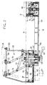
- die Vorderansicht einer erfindungsgemäßen Sägeblatt-Klemmvorrichtung und
- Fig. 2
- den abgewinkelten Schnitt II-II in Fig. 1.
- Fig. 1
- the front view of a saw blade clamping device according to the invention and
- Fig. 2
- the angled section II-II in Fig. 1st
Zum Klemmen eines Sägeblattes 10 - dargestellt ist als Beispiel ein Bandsägeblatt - sind ein ortsfester Klemmbacken 12 und ein beweglicher Klemmbacken 14 vorgesehen. Der bewegliche Klemmbacken 14 ist gelenkig an einem Kopfstück 16 abgestützt, das über einen abgewinkelten Arm 18 an einem Tragkörper 20 befestigt ist. Der Tragkörper 20 ist über eine Viergelenkanordnung 22 an einer Rückwand 24 einer gehäuseartigen Konsole 26 gelagert. Die Konsole 26 ist dazu bestimmt, an einem mit strichpunktierten Linien angedeuteten Maschinengestell 28 einer Sägenbearbeitungsmaschine befestigt zu werden, an der auch der ortsfeste Klemmbacken 12 abgestützt ist.To clamp a saw blade 10 - a band saw blade is shown as an example - a
Die Viergelenkanordnung 22 ist von allen Spannkräften sowie vom Eigengewicht des beweglichen Klemmbackens 14 sowie der genannten, ihn tragenden Bauteile einschließlich des Tragkörpers 20 dadurch entlastet, daß letzterer in einer Flachführung 30 geführt ist, die an der Vorderseite der Konsole 26 ausgebildet ist. Die Viergelenkanordnung 22 hat zwei Gelenkgabeln 32, die an der Rückwand 24 befestigt und durch je einen Lenker 34 bzw. 36 mit je einer von zwei am Tragkörper 20 befestigten Gelenkgabeln 38 verbunden sind. Im dargestellten Beispiel sind die Lenker 34 und 36 gleichlang, die Gelenkgabeln 32 in gleichen Abständen voneinander angeordnet wie die Gelenkgabeln 38 und außerdem ist die Verbindungslinie der beiden Gelenke an den Gelenkgabeln 32 parallel zur Verbindungslinie der beiden Gelenke an den Gelenkgabeln 38.The four-
Infolgedessen ist die dargestellte Viergelenkanordnung 22 eine Parallelogrammlenkeranordnung, die dafür sorgt, daß der Arm 18 bei all seinen Bewegungen parallel zur Ebene des Sägeblattes 10 bleibt. Durch geringfügige Änderung eines der genannten Gelenkabstände oder der Länge des einen oder anderen Lenkers 34 oder 36 kann jedoch dafür gesorgt werden, daß die Viergelenkanordnung 22 beim Öffnen der Klemmvorrichtung zunächst eine kleine Schwenkung des beweglichen Klemmbackens 14 von der Sägeblattebene weg und dann eine zur Sägeblattebene im wesentlichen parallele Weiterbewegung bewirkt.As a result, the four-
Die Flachführung 30 erstreckt sich schräg nach oben vom Sägeblatt 10 weg, im dargestellten Beispiel unter einem Winkel von etwa 40° gegen die Waagerechte. Dementsprechend sind die Lenker 34 und 36 in einer - vorzugsweise gemeinsamen - schrägen Ebene schwenkbar. Um die Aufwärtsbewegung des Tragkörpers 20 und der mit ihm verbundenen Bauteile zu erleichtern, ist eine Gewichtsausgleichsvorrichtung 40 vorgesehen; diese ist im dargestellten Beispiel eine Gasfeder, die mit einem Ende am Lenker 34 und mit ihrem anderen Ende an der Konsole 26 angelenkt ist.The
Der Tragkörper 20 ist zwischen zwei parallelen Führungsflächen 42 der Flachführung 30 im wesentlichen spielfrei geführt. Die Führungsflächen 42 können Gleitflächen sein, die entsprechende Gleitflächen des Tragkörpers 20 unmittelbar berühren. Alternativ können in die Führungsflächen 42 oder in den Tragkörper 20 Kugeln eingebettet sein, um die Bewegungen des Tragkörpers von Gleitreibung freizuhalten. Zur Flachführung 30 gehört im dargestellten Beispiel ferner ein Paar Klemmflächen 44, die sich in einem Abstand voneinander normal zu den Führungsflächen 42 in je einer senkrechten Ebene erstrecken und durch den Zwischenraum zwischen den Führungsflächen 42 unterbrochen sind.The
Durch diesen Zwischenraum sowie durch den Tragkörper 20 und das daran befestigte Ende des Arms 18 hindurch erstreckt sich eine waagerechte, zu den Klemmflächen 44 normale Welle 46, die im Tragkörper 20 axial verschiebbar gelagert ist. Am äußeren Ende der Welle 46 ist eine Nabe 48 befestigt, die einen Spannhebel 50 trägt; am inneren Ende ist ein Nocken 52 befestigt, der eine der inneren Klemmfläche 44 zugewandte Stirnfläche in der Art einer Axialkurvenscheibe aufweist. Der Nocken 52 liegt an einem Wellenbund 54 an und ist durch ein Paar Muttern 56 festgehalten.A
Innerhalb eines Hohlraums des Arms 18 ist eine Druckfeder 58 in Gestalt eines Tellerfederpakets zwischen dem Tragkörper 20 und einem Paar auf die Welle 46 aufgeschraubter Muttern 60 derart eingespannt, daß die Welle 46 in ihrer Achsrichtung nach außen vorgespannt und dadurch bestrebt ist, den Nocken an der inneren Klemmfläche 44 anliegend zu halten. Die Welle 46 läßt sich mit dem Spannhebel 50 zwischen einer Lösestellung und einer Spannstellung verdrehen. In der Lösestellung ist der Tragkörper 20 in der Flachführung 30 frei verschiebbar; in der Klemmstellung ist er - und somit auch der Arm 18 - mit der Konsole 26 starr verspannt.Within a cavity of the
Die Flachführung 30 und der Innenraum der Konsole 26 sind durch Faltenbälge 62 vor Verschmutzung geschützt.The
Da die Klemmvorrichtung im dargestellten Beispiel für eine waagerecht angeordnete Bandsäge vorgesehen ist, weist der Arm 18 einen waagerechten Schenkel 64 und einen entsprechend der Neigung der Flachführung 30 geneigten Schenkel 66 auf. Am freien Ende des waagerechten Schenkels 64 ist der bewegliche Klemmbacken 14 mittels eines Kugelgelenks 68 abgestützt; zu diesem gehört eine im Kopfstück 16 normal zur Sägeblattebene, also waagerecht, verschiebbar geführte Gelenkpfanne 70, die durch eine zentrale Feder 72 in Richtung zum Sägeblatt 10 hin vorgespannt ist. Dieser Vorspannung wirken Schrauben 74 entgegen, die durch je eine Distanzbüchse 76 hindurch in den beweglichen Klemmbacken 14 eingeschraubt sind und sich über je eine Feder 78, z.B. ein Tellerfederpaket, am Kopfstück 16 abstützen. Die Distanzbüchsen 76 haben im Kopfstück 16 radiales Spiel. Somit ist dafür gesorgt, daß der bewegliche Klemmbacken 14 kleine Schwenkungen ausführen kann, um sich dem Sägeblatt 10 auch dann anpassen zu können, wenn der Arm 18 gegen die Sägeblattebene leicht geneigt sein sollte.Since the clamping device is provided in the example shown for a horizontally arranged band saw, the
Claims (8)
- A saw blade clamping device for saw finishing machines, comprising a stationary clamping jaw (12) and a movable clamping jaw (14) which is hingedly connected to a bracket (26) and adapted to be fastened in clamping position in which it presses a saw blade (10) against the stationary clamping jaw (12), characterized in that the movable jaw (14) is carried by a support member (20) which is guided for displacement on the bracket (26) by a flat guide means (30) to cause a slightly arcuate movement, deviating only a little from the plane of the saw blade, of the movable clamping jaw (14) away from the stationary clamping jaw (12), which support member further is adapted to be clamped to the bracket (26) and is connected to the same in addition by a four-joint arrangement (22).
- The saw blade clamping device as claimed in claim 1, characterized in that the flat guide means (30) has two parallel, planar guide surfaces (42) facing each other and extending at right angles to the plane of the saw blade, the support member (20) being displaceable between them.
- The saw blade clamping device as claimed in claim 2, characterized in that the flat guide means (30) is inclined with respect to the horizontal.
- The saw blade clamping device as claimed in claim 3, characterized in that the four-joint arrangement (22) comprises a weight balancing means (40).
- The saw blade clamping device as claimed in claim 3 or 4, characterized in that the movable clamping jaw (14) is connected to the support member (20) by a cranked arm (18) which includes a horizontal limb (64) and a limb (66) inclined in accordance with the inclination of the flat guide means (30).
- The saw blade clamping device as claimed in any one of claims 1 to 5, characterized in that the four-joint arrangement (22) comprises two parallel links (34, 36).
- The saw blade clamping device as claimed in any one of claims 1 to 6, characterized in that the support member (20) supports a shaft (46) which carries a clamping lever (50) at one end and a cam (52) at the other end, the cam being adapted to be clamped at the flat guide means (30) by turning of the clamping lever (50).
- The saw blade clamping device as claimed in claim 7 in combination with claim 2, characterized in that the flat guide means (30) has two clamping surfaces (44) for the cam (52) extending parallel to the plane of the saw blade.
Applications Claiming Priority (3)
| Application Number | Priority Date | Filing Date | Title |
|---|---|---|---|
| DE4115319A DE4115319C1 (en) | 1991-05-10 | 1991-05-10 | |
| DE4115319 | 1991-05-10 | ||
| PCT/EP1992/001009 WO1992020486A1 (en) | 1991-05-10 | 1992-05-08 | Saw blade clamping device for saw processing machines |
Publications (2)
| Publication Number | Publication Date |
|---|---|
| EP0538440A1 EP0538440A1 (en) | 1993-04-28 |
| EP0538440B1 true EP0538440B1 (en) | 1994-10-19 |
Family
ID=6431412
Family Applications (1)
| Application Number | Title | Priority Date | Filing Date |
|---|---|---|---|
| EP92910204A Expired - Lifetime EP0538440B1 (en) | 1991-05-10 | 1992-05-08 | Saw blade clamping device for saw processing machines |
Country Status (6)
| Country | Link |
|---|---|
| US (1) | US5297455A (en) |
| EP (1) | EP0538440B1 (en) |
| JP (1) | JP3410091B2 (en) |
| DE (2) | DE4115319C1 (en) |
| ES (1) | ES2061341T3 (en) |
| WO (1) | WO1992020486A1 (en) |
Families Citing this family (1)
| Publication number | Priority date | Publication date | Assignee | Title |
|---|---|---|---|---|
| CN112476281A (en) * | 2020-11-20 | 2021-03-12 | 嘉善永溢达精密五金有限公司 | Clamping device is used in pipe fitting processing |
Family Cites Families (4)
| Publication number | Priority date | Publication date | Assignee | Title |
|---|---|---|---|---|
| DE874551C (en) * | 1939-05-14 | 1953-04-23 | Heinrich Vollmer | Saw blade clamping device on sharpening and twisting machines |
| DE901727C (en) * | 1950-03-07 | 1954-01-14 | Vollmerwerke Maschinenfabrik G | Saw blade clamping device on saw sharpening machines |
| FR2516829A1 (en) * | 1981-11-25 | 1983-05-27 | Trouillot Raymond | Sliding guide for mounting band saw blade during sharpening - is height adjustable top rail pin jointed to parallelogram frame |
| DE3600882A1 (en) * | 1986-01-15 | 1987-07-16 | Helmut Ebertseder | Apparatus for holding a hand plane with an electric motor-driven knife |
-
1991
- 1991-05-10 DE DE4115319A patent/DE4115319C1/de not_active Expired - Fee Related
-
1992
- 1992-05-08 DE DE59200655T patent/DE59200655D1/en not_active Expired - Fee Related
- 1992-05-08 EP EP92910204A patent/EP0538440B1/en not_active Expired - Lifetime
- 1992-05-08 JP JP50916592A patent/JP3410091B2/en not_active Expired - Fee Related
- 1992-05-08 ES ES92910204T patent/ES2061341T3/en not_active Expired - Lifetime
- 1992-05-08 US US07/958,364 patent/US5297455A/en not_active Expired - Fee Related
- 1992-05-08 WO PCT/EP1992/001009 patent/WO1992020486A1/en active IP Right Grant
Also Published As
| Publication number | Publication date |
|---|---|
| DE59200655D1 (en) | 1994-11-24 |
| WO1992020486A1 (en) | 1992-11-26 |
| US5297455A (en) | 1994-03-29 |
| JP3410091B2 (en) | 2003-05-26 |
| JPH06500054A (en) | 1994-01-06 |
| ES2061341T3 (en) | 1994-12-01 |
| EP0538440A1 (en) | 1993-04-28 |
| DE4115319C1 (en) | 1992-04-30 |
Similar Documents
| Publication | Publication Date | Title |
|---|---|---|
| DE69708162T3 (en) | PURPOSE OF USE FOR THE DISPOSAL OF HARMFUL SMOKE GASES FROM A WORKSTATION | |
| DE3329496A1 (en) | CAP AND MITER SAW | |
| DE19832984A1 (en) | Circular saw with bench | |
| EP3597379B1 (en) | Knife | |
| DE602004008336T2 (en) | DEVICE FOR SHARPENING CHAINSAW TANGES | |
| DE102007012394A1 (en) | Handle of a hand-held machine tool | |
| EP2002060B1 (en) | Apparatus for grinding rails of a track | |
| EP0754829B1 (en) | Device for the attachment of a pivoting element, for example of a vehicle hood to a body, for example to a vehicle frame | |
| DE60210218T2 (en) | Miter Saw | |
| EP4028599B1 (en) | Gripper | |
| EP0538440B1 (en) | Saw blade clamping device for saw processing machines | |
| DE3840163A1 (en) | HANGING DEVICE FOR A HAND MACHINE TOOL | |
| EP0575586A1 (en) | Anti-splinter device for sawing machines with a saw blade. | |
| DE3347920C2 (en) | Sawing device | |
| DE102009040851B4 (en) | Log splitter with protective bow arrangement | |
| DE4117949C2 (en) | Mechanical overload protection for bed and rotary plows | |
| EP0474020B1 (en) | Security ski binding with horizontally swingable sole hold-forms | |
| EP0781630B1 (en) | Clamping device | |
| EP0802036A2 (en) | Apparatus for butt-welding of thermoplastic pipes | |
| AT396491B (en) | Device for the detachable fastening of an implement to a vehicle | |
| EP1008550B1 (en) | Mechanical arrangement for limiting the movement of working platforms | |
| EP1098037B1 (en) | Rail severing apparatus | |
| DE4028456C1 (en) | Bench-desk adjusting top - has frame cross bar, two pairs of swivel arms, dovetail groove and clamp | |
| DE3711358A1 (en) | Mitre saw | |
| DE102007019155B4 (en) | Ride-on mower with mower deck |
Legal Events
| Date | Code | Title | Description |
|---|---|---|---|
| PUAI | Public reference made under article 153(3) epc to a published international application that has entered the european phase |
Free format text: ORIGINAL CODE: 0009012 |
|
| 17P | Request for examination filed |
Effective date: 19930107 |
|
| AK | Designated contracting states |
Kind code of ref document: A1 Designated state(s): CH DE ES FR GB IT LI |
|
| 17Q | First examination report despatched |
Effective date: 19931123 |
|
| GRAA | (expected) grant |
Free format text: ORIGINAL CODE: 0009210 |
|
| ITF | It: translation for a ep patent filed |
Owner name: BARZANO' E ZANARDO MILANO S.P.A. |
|
| AK | Designated contracting states |
Kind code of ref document: B1 Designated state(s): CH DE ES FR GB IT LI |
|
| REF | Corresponds to: |
Ref document number: 59200655 Country of ref document: DE Date of ref document: 19941124 |
|
| REG | Reference to a national code |
Ref country code: ES Ref legal event code: FG2A Ref document number: 2061341 Country of ref document: ES Kind code of ref document: T3 |
|
| GBT | Gb: translation of ep patent filed (gb section 77(6)(a)/1977) |
Effective date: 19941104 |
|
| ET | Fr: translation filed | ||
| PLBE | No opposition filed within time limit |
Free format text: ORIGINAL CODE: 0009261 |
|
| STAA | Information on the status of an ep patent application or granted ep patent |
Free format text: STATUS: NO OPPOSITION FILED WITHIN TIME LIMIT |
|
| 26N | No opposition filed | ||
| REG | Reference to a national code |
Ref country code: GB Ref legal event code: IF02 |
|
| PGFP | Annual fee paid to national office [announced via postgrant information from national office to epo] |
Ref country code: ES Payment date: 20040312 Year of fee payment: 13 |
|
| PGFP | Annual fee paid to national office [announced via postgrant information from national office to epo] |
Ref country code: GB Payment date: 20040317 Year of fee payment: 13 Ref country code: FR Payment date: 20040317 Year of fee payment: 13 Ref country code: CH Payment date: 20040317 Year of fee payment: 13 |
|
| PGFP | Annual fee paid to national office [announced via postgrant information from national office to epo] |
Ref country code: DE Payment date: 20040525 Year of fee payment: 13 |
|
| PG25 | Lapsed in a contracting state [announced via postgrant information from national office to epo] |
Ref country code: IT Free format text: LAPSE BECAUSE OF NON-PAYMENT OF DUE FEES;WARNING: LAPSES OF ITALIAN PATENTS WITH EFFECTIVE DATE BEFORE 2007 MAY HAVE OCCURRED AT ANY TIME BEFORE 2007. THE CORRECT EFFECTIVE DATE MAY BE DIFFERENT FROM THE ONE RECORDED. Effective date: 20050508 Ref country code: GB Free format text: LAPSE BECAUSE OF NON-PAYMENT OF DUE FEES Effective date: 20050508 |
|
| PG25 | Lapsed in a contracting state [announced via postgrant information from national office to epo] |
Ref country code: ES Free format text: LAPSE BECAUSE OF NON-PAYMENT OF DUE FEES Effective date: 20050509 |
|
| PG25 | Lapsed in a contracting state [announced via postgrant information from national office to epo] |
Ref country code: LI Free format text: LAPSE BECAUSE OF NON-PAYMENT OF DUE FEES Effective date: 20050531 Ref country code: CH Free format text: LAPSE BECAUSE OF NON-PAYMENT OF DUE FEES Effective date: 20050531 |
|
| PG25 | Lapsed in a contracting state [announced via postgrant information from national office to epo] |
Ref country code: DE Free format text: LAPSE BECAUSE OF NON-PAYMENT OF DUE FEES Effective date: 20051201 |
|
| REG | Reference to a national code |
Ref country code: CH Ref legal event code: PL |
|
| GBPC | Gb: european patent ceased through non-payment of renewal fee |
Effective date: 20050508 |
|
| PG25 | Lapsed in a contracting state [announced via postgrant information from national office to epo] |
Ref country code: FR Free format text: LAPSE BECAUSE OF NON-PAYMENT OF DUE FEES Effective date: 20060131 |
|
| REG | Reference to a national code |
Ref country code: FR Ref legal event code: ST Effective date: 20060131 |
|
| REG | Reference to a national code |
Ref country code: ES Ref legal event code: FD2A Effective date: 20050509 |