EP0538186A1 - Height-adjustable support for laboratory equipment - Google Patents
Height-adjustable support for laboratory equipment Download PDFInfo
- Publication number
- EP0538186A1 EP0538186A1 EP92810716A EP92810716A EP0538186A1 EP 0538186 A1 EP0538186 A1 EP 0538186A1 EP 92810716 A EP92810716 A EP 92810716A EP 92810716 A EP92810716 A EP 92810716A EP 0538186 A1 EP0538186 A1 EP 0538186A1
- Authority
- EP
- European Patent Office
- Prior art keywords
- holding device
- tripod
- stand
- spindle
- rod
- Prior art date
- Legal status (The legal status is an assumption and is not a legal conclusion. Google has not performed a legal analysis and makes no representation as to the accuracy of the status listed.)
- Granted
Links
Images

Classifications
-
- B—PERFORMING OPERATIONS; TRANSPORTING
- B01—PHYSICAL OR CHEMICAL PROCESSES OR APPARATUS IN GENERAL
- B01L—CHEMICAL OR PHYSICAL LABORATORY APPARATUS FOR GENERAL USE
- B01L9/00—Supporting devices; Holding devices
- B01L9/04—Retort stands; Retort clamps
-
- B—PERFORMING OPERATIONS; TRANSPORTING
- B01—PHYSICAL OR CHEMICAL PROCESSES OR APPARATUS IN GENERAL
- B01D—SEPARATION
- B01D3/00—Distillation or related exchange processes in which liquids are contacted with gaseous media, e.g. stripping
- B01D3/08—Distillation or related exchange processes in which liquids are contacted with gaseous media, e.g. stripping in rotating vessels; Atomisation on rotating discs
- B01D3/085—Distillation or related exchange processes in which liquids are contacted with gaseous media, e.g. stripping in rotating vessels; Atomisation on rotating discs using a rotary evaporator
-
- Y—GENERAL TAGGING OF NEW TECHNOLOGICAL DEVELOPMENTS; GENERAL TAGGING OF CROSS-SECTIONAL TECHNOLOGIES SPANNING OVER SEVERAL SECTIONS OF THE IPC; TECHNICAL SUBJECTS COVERED BY FORMER USPC CROSS-REFERENCE ART COLLECTIONS [XRACs] AND DIGESTS
- Y10—TECHNICAL SUBJECTS COVERED BY FORMER USPC
- Y10S—TECHNICAL SUBJECTS COVERED BY FORMER USPC CROSS-REFERENCE ART COLLECTIONS [XRACs] AND DIGESTS
- Y10S203/00—Distillation: processes, separatory
- Y10S203/02—Laboratory distillation
-
- Y—GENERAL TAGGING OF NEW TECHNOLOGICAL DEVELOPMENTS; GENERAL TAGGING OF CROSS-SECTIONAL TECHNOLOGIES SPANNING OVER SEVERAL SECTIONS OF THE IPC; TECHNICAL SUBJECTS COVERED BY FORMER USPC CROSS-REFERENCE ART COLLECTIONS [XRACs] AND DIGESTS
- Y10—TECHNICAL SUBJECTS COVERED BY FORMER USPC
- Y10T—TECHNICAL SUBJECTS COVERED BY FORMER US CLASSIFICATION
- Y10T74/00—Machine element or mechanism
- Y10T74/18—Mechanical movements
- Y10T74/18568—Reciprocating or oscillating to or from alternating rotary
- Y10T74/18832—Reciprocating or oscillating to or from alternating rotary including flexible drive connector [e.g., belt, chain, strand, etc.]
- Y10T74/18848—Reciprocating or oscillating to or from alternating rotary including flexible drive connector [e.g., belt, chain, strand, etc.] with pulley
-
- Y—GENERAL TAGGING OF NEW TECHNOLOGICAL DEVELOPMENTS; GENERAL TAGGING OF CROSS-SECTIONAL TECHNOLOGIES SPANNING OVER SEVERAL SECTIONS OF THE IPC; TECHNICAL SUBJECTS COVERED BY FORMER USPC CROSS-REFERENCE ART COLLECTIONS [XRACs] AND DIGESTS
- Y10—TECHNICAL SUBJECTS COVERED BY FORMER USPC
- Y10T—TECHNICAL SUBJECTS COVERED BY FORMER US CLASSIFICATION
- Y10T74/00—Machine element or mechanism
- Y10T74/19—Gearing
- Y10T74/19642—Directly cooperating gears
- Y10T74/19698—Spiral
- Y10T74/19702—Screw and nut
- Y10T74/19735—Nut disengageable from screw
Definitions
- the invention relates to a height-adjustable stand for laboratory devices, in particular for rotary evaporators, according to the preamble of patent claims 1 and 13.
- Height-adjustable tripods for laboratory devices, in particular for rotary evaporators are known and used in a wide variety of embodiments.
- EP-A1-149 972 a height-adjustable tripod, in which the holding device of the tripod can be raised and lowered with the aid of an energy store.
- a lifting device for a rotary evaporator is known, in which a holding device which is vertically displaceable on the stand rod can be raised or lowered by means of a spindle.
- the spindle is driven by an electric motor.
- the lifting device can be controlled by switching the motor on and off.
- a major problem of such lifting devices is that, on the one hand, they should be able to be raised or lowered relatively slowly during operation. On the other hand, situations can arise in which very quick lifting is necessary. This occurs e.g. in the case of rotary evaporators, when the evaporating flask has to be quickly lifted out of the heating bath to interrupt an evaporation process or a reaction.
- the height of the holding device should also be manually adjustable, which is not possible with conventional motor drives.
- the invention has for its object to avoid the disadvantages of the known, in particular a height-adjustable tripod and a method for height adjustment of the holding device to create a tripod which, with the simplest construction, enables both manual and motorized adjustment in any operating position, ie both when the drive motor is activated and when the drive motor is at a standstill.
- the coupling is provided between the holding device which can be displaced on the stand rod and the lifting device.
- the holding device can be disengaged at any time, with the engine stopped or running. In this way, one can intervene extremely quickly in the process sequence.
- a lifting or lowering process can also be interrupted by simply releasing the clutch while the engine is running. If the drive motor fails, the holding device can also be easily raised or lowered manually and locked again by simply engaging it.
- the invention can be implemented particularly easily if the lifting device is an endless conveyor arranged approximately parallel to the stand rod.
- Spindle drives, rotating belt, belt or chain drives have proven particularly useful as endless conveyors.
- the holding device When at a standstill, the holding device is coupled to the conveyor by the coupling device and thereby locked at the respective height.
- the lifting or lowering movement of the holding device can be interrupted at any time by disengaging the coupling device by disengaging it. In this case, the endless conveyor simply continues to run until it is switched off. Then the clutch can be reinserted.
- Driver elements which can be brought into engagement with the conveyor by force-locking or positive locking, have proven particularly useful as couplings.
- the driver element When using a spindle drive the driver element can be any claw arrangement that can be inserted into the spindle gears and can be carried by them. This results in particularly good power transmission if the driver element is designed as a type of partial thread, which can be laterally complementarily engaged with the spindle.
- the driver element can e.g. a gear-like element are laterally pressed into the chain links.
- any clamping arrangements can be provided, e.g. be under spring tension and jammed with the running belt or the standing belt.
- the invention can be implemented particularly advantageously if a handle for gripping and manual lowering or lifting is provided on the holding device.
- One-handed engagement and disengagement can be accomplished particularly well if an actuating element for the clutch is provided on the handle.
- a stand 1 for a rotary evaporator has a base plate 2 with a heating device 3 and a heating bath 4.
- a stand rod 5 is on the base plate 2 attached, which carries a holding device 6.
- a rotary drive 7 (not shown in more detail) for the evaporator piston 8 is attached to the holding device 6.
- an electric motor 9 is provided which carries a spindle 11 which is arranged parallel to the stand rod 5 and can be rotated in a bearing 10.
- the spindle 11 runs through a bore 6a in the holding device 6, in which it can rotate freely.
- a coupling 12 is provided on the holding device 6, with which the holding device 6 can be brought into drive connection with the spindle 11.
- the coupling 12 has a lever 14 which can be pivoted on a joint 13 and which has on its side facing the spindle 11 a number of claws 15 which engage in the spindle thread.
- the lever is pressed against the spindle 11 by a spring 17 in such a way that the claws engage firmly in the spindle 11 and ensure drive connection between the spindle 11 and the holding device 6.
- the lever 14 is actuated clockwise, the claws 15 are obviously separated from the spindle 11, so that the holding device 6 can be moved on the stand rod 5 by hand.
- Such actuation can e.g. take place with the spindle 11 stationary in order to manually raise or lower the holding device 6 or the evaporating piston 8. But even with the spindle 11 rotating, the lever 14 can be operated, e.g. to prevent the evaporator flask from lowering or hitting too deeply.
- the coupling 12 can also be provided with an electrical actuating element.
- an electric pull magnet could act on the lever 14, which swivels the lever into the engagement or disengagement position.
- a rotating V-belt 20 is provided instead of a spindle, which is driven by a drive wheel 21 and deflected by two deflection wheels 22, 23.
- the drive wheel 21 can be driven by a drive motor, not shown, in both directions of rotation.
- the coupling consists of a clamping device with a clamping part 24 fixedly attached to the holding device 6 and a movable clamping part 25, which is biased by the spring 17 in the direction of the fixed clamping part 24 such that between the two clamping parts 24 or 25 the V-belt 20 is gripped and held non-positively.
- each movement of the V-belt 20 therefore causes the holding device 6 to be raised or lowered.
- the lever 14 is actuated against the force of the spring 17, so that the clamping part 25 releases the V-belt 20.
- a handle 26 is provided on the holding device 6, by means of which the holding device 6 can be raised or lowered manually on the stand rod 5 after disengagement.
- the clutch 12 has a lever 27 which is pivotable about a pivot point 28.
- the lever 27 is provided on its side facing the spindle 11 with a number of partial threads 29.
- the spring 17 presses the lever 27 or the partial threads 29 against the spindle 11 in such a way that a positive drive connection is created.
- the lever 27 is connected by means of a pull rod 30 to an actuating element 31, which is on the handle 26 is arranged.
- the lever 27 can first be pivoted against the spring force 17 by pressure on the actuating element 31 and the holding device 6 can thereby be disengaged from the spindle 11. Thereafter, the holding device 6 can be raised or lowered in a simple manner by means of the handle 26.
- the lifting device could also have a standing rack instead of the spindle 11, into which a worm wheel attached to the holding device 6 engages, which is driven by a motor also attached to the holding device 6.
- a worm wheel attached to the holding device 6 engages, which is driven by a motor also attached to the holding device 6.
Abstract
Description
Die Erfindung betrifft ein höhenverstellbares Stativ für Laborgeräte, insbesondere für Rotationsverdampfer gemäss Oberbegriff von Patentanspruch 1 und 13.The invention relates to a height-adjustable stand for laboratory devices, in particular for rotary evaporators, according to the preamble of
Höhenverstellbare Stative für Laborgeräte, insbesondere für Rotationsverdampfer sind in den verschiedensten Ausführungsformen bekannt und gebräuchlich. So zeigt z.B. die EP-A1-149 972 ein höhenverstellbares Stativ, bei welchem die Halteeinrichtung des Stativs mit Hilfe eines Kraftspeichers anhebbar und absenkbar ist. Aus der CH-PS-664 503 ist eine Hubvorrichtung für einen Rotationsverdampfer bekannt, bei welchem eine an der Stativstange vertikal verschiebbare Halteeinrichtung mittels einer Spindel angehoben bzw. abgesenkt werden kann. Die Spindel wird durch einen Elektromotor angetrieben. Durch Einschalten und Ausschalten des Motors lässt sich die Hubvorrichtung steuern.Height-adjustable tripods for laboratory devices, in particular for rotary evaporators, are known and used in a wide variety of embodiments. For example, EP-A1-149 972 a height-adjustable tripod, in which the holding device of the tripod can be raised and lowered with the aid of an energy store. From CH-PS-664 503 a lifting device for a rotary evaporator is known, in which a holding device which is vertically displaceable on the stand rod can be raised or lowered by means of a spindle. The spindle is driven by an electric motor. The lifting device can be controlled by switching the motor on and off.
Ein wesentliches Problem derartiger Hubvorrichtungen besteht darin, dass sie einerseits relativ langsam im Betrieb anhebbar oder absenkbar sein sollen. Anderseits können sich jedoch Situationen ergeben, in denen ein sehr schnelles Anheben notwendig wird. Dies tritt z.B. bei Rotationsverdampfern auf, wenn der Verdampferkolben schnell aus dem Heizbad gehoben werden muss, um einen Verdampfungsvorgang oder eine Reaktion zu unterbrechen. Auch sollte die Höhe der Haltevorrichtung manuell einstellbar sein, was bei den konventionellen Motorantrieben nicht möglich ist.A major problem of such lifting devices is that, on the one hand, they should be able to be raised or lowered relatively slowly during operation. On the other hand, situations can arise in which very quick lifting is necessary. This occurs e.g. in the case of rotary evaporators, when the evaporating flask has to be quickly lifted out of the heating bath to interrupt an evaporation process or a reaction. The height of the holding device should also be manually adjustable, which is not possible with conventional motor drives.
Der Erfindung liegt die Aufgabe zugrunde, die Nachteile des Bekannten zu vermeiden, insbesondere also ein höhenverstellbares Stativ und ein Verfahren zur Höhenverstellung der Halteeinrichtung eines Stativs zu schaffen, die bei einfachstem Aufbau sowohl manuelle als auch motorische Verstellung in jeder beliebigen Betriebslage, d.h. sowohl bei aktiviertem Antriebsmotor als auch bei stillstehendem Antriebsmotor ermöglichen.The invention has for its object to avoid the disadvantages of the known, in particular a height-adjustable tripod and a method for height adjustment of the holding device to create a tripod which, with the simplest construction, enables both manual and motorized adjustment in any operating position, ie both when the drive motor is activated and when the drive motor is at a standstill.
Erfindungsgemäss wird diese Aufgabe gemäss Kennzeichen der Patentansprüche gelöst.According to the invention, this object is achieved in accordance with the characteristics of the claims.
Wesentlich für die Erfindung ist dabei also, dass die Kupplung zwischen der an der Stativstange verschiebbaren Halteeinrichtung und der Hubeinrichtung vorgesehen ist. Auf diese Weise kann die Halteeinrichtung zu jedem beliebigen Zeitpunkt, bei stillstehendem oder laufendem Motor ausgekuppelt werden. Auf diese Weise lässt sich einerseits ausserordentlich schnell in den Verfahrensablauf eingreifen. Anderseits kann auch ein Hub- oder Absenk-Vorgang unterbrochen werden, indem einfach bei laufendem Motor die Kupplung gelöst wird. Bei Ausfall des Antriebsmotors lässt sich ebenfalls ohne weiteres die Halteeinrichtung manuell anheben oder absenken und durch einfaches Einkuppeln wieder fest arretieren.It is therefore essential for the invention that the coupling is provided between the holding device which can be displaced on the stand rod and the lifting device. In this way, the holding device can be disengaged at any time, with the engine stopped or running. In this way, one can intervene extremely quickly in the process sequence. On the other hand, a lifting or lowering process can also be interrupted by simply releasing the clutch while the engine is running. If the drive motor fails, the holding device can also be easily raised or lowered manually and locked again by simply engaging it.
Besonders einfach lässt sich die Erfindung realisieren, wenn die Hubeinrichtung ein etwa parallel zur Stativstange angeordneter Endlos-Vörderer ist. Als Endlos-Vörderer haben sich besonders bewährt Spindelantriebe, umlaufende Riemen-, Band- oder Kettenantriebe. Bei Stillstand wird durch die Kupplungseinrichtung die Halteeinrichtung mit dem Vörderer gekoppelt und dadurch in der jeweiligen Höhe arretiert. Im Betrieb kann durch Auskuppeln jederzeit die Hub- oder Absenkbewegung der Halteeinrichtung dadurch unterbrochen werden, dass die Kupplungseinrichtung gelöst wird. Der endlose Vörderer läuft in einem solchen Fall einfach weiter, bis er abgeschaltet wird. Danach kann die Kupplung wieder eingelegt werden. Als Kupplungen haben sich besonders Mitnehmer-Elemente bewährt, die sich durch Kraftschluss oder Formschluss mit dem Förder in Eingriff bringen lassen. Bei Verwendung eines Spindelantriebs kann das Mitnehmer-Element eine beliebige Klauenanordnung sein, die in die Spindelgänge einlegbar und durch diese mitnehmbar ist. Dabei ergibt sich besonders gute Kraftübertragung, wenn das Mitnehmer-Element als eine Art Teil-Gewinde ausgebildet ist, das seitlich komplementrär mit der Spindel in Eingriff bringbar ist.The invention can be implemented particularly easily if the lifting device is an endless conveyor arranged approximately parallel to the stand rod. Spindle drives, rotating belt, belt or chain drives have proven particularly useful as endless conveyors. When at a standstill, the holding device is coupled to the conveyor by the coupling device and thereby locked at the respective height. During operation, the lifting or lowering movement of the holding device can be interrupted at any time by disengaging the coupling device by disengaging it. In this case, the endless conveyor simply continues to run until it is switched off. Then the clutch can be reinserted. Driver elements, which can be brought into engagement with the conveyor by force-locking or positive locking, have proven particularly useful as couplings. When using a spindle drive the driver element can be any claw arrangement that can be inserted into the spindle gears and can be carried by them. This results in particularly good power transmission if the driver element is designed as a type of partial thread, which can be laterally complementarily engaged with the spindle.
Bei Kettenförderern kann als Mitnehmer-Element z.B. ein zahnradartig ausgebildetes Element seitlich in die Kettenglieder eingepresst werden. Bei Band- oder Riemenförderern können beliebige Klemmanordnungen vorgesehen werden, die z.B. unter Federspannung stehen und mit dem laufenden Band oder dem stehenden Band verklemmt werden.For chain conveyors, the driver element can e.g. a gear-like element are laterally pressed into the chain links. With belt or belt conveyors, any clamping arrangements can be provided, e.g. be under spring tension and jammed with the running belt or the standing belt.
Besonders vorteilhaft lässt sich die Erfindung realisieren, wenn an der Halteeinrichtung ein Handgriff zum Ergreifen und manuellen Absenken oder Abheben vorgesehen ist. Dabei kann einhändiges Einkuppeln und Auskuppeln besonders gut bewerkstelligt werden, wenn am Handgriff ein Betätigungselement für die Kupplung vorgesehen ist.The invention can be implemented particularly advantageously if a handle for gripping and manual lowering or lifting is provided on the holding device. One-handed engagement and disengagement can be accomplished particularly well if an actuating element for the clutch is provided on the handle.
Die Erfindung ist im folgenden in Ausführungsbeispielen und anhand der Zeichnungen näher erläutert. Es zeigen:
- Figur 1 die schematische Darstellung eines Stativs mit den Merkmalen der Erfindung,
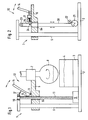
- Figur 2 ein abgewandeltes Ausführungsbeispiel eines Stativs mit den Merkmalen der Erfindung, und
- Figur 3 und 4 ein erfindungsgemässes Stativ im Ausschnitt in schematischer Seitenansicht bzw. in Draufsicht.
- FIG. 1 shows the schematic representation of a tripod with the features of the invention,
- Figure 2 shows a modified embodiment of a tripod with the features of the invention, and
- Figures 3 and 4 a tripod according to the invention in a detail in a schematic side view and in plan view.
Gemäss Figur 1 weist ein Stativ 1 für einen Rotationsverdampfer eine Grundplatte 2 mit einer Heizvorrichtung 3 und einem Heizbad 4 auf. Auf der Grundplatte 2 ist eine Stativstange 5 befestigt, welche eine Halteeinrichtung 6 trägt. An der Halteeinrichtung 6 ist ein nicht näher dargestellter Dreh-Antrieb 7 für den Verdampferkolben 8 befestigt. Zum Abheben und Absenken der Halteeinrichtung 6 bzw. des Verdampferkolbens 8 in das Heizbad 4 bzw. aus dem Heizbad 4 ist ein Elektro-Motor 9 vorgesehen, der eine parallel zur Stativstange 5 angeordnete, und in einem Lager 10 drehbare Spindel 11 trägt. Die Spindel 11 läuft durch eine Bohrung 6a in der Halteeinrichtung 6, in der sie sich frei drehen kann. Auf der Halteeinrichtung 6 ist eine Kupplung 12 vorgesehen, mit welcher die Halteeinrichtung 6 mit der Spindel 11 in Antriebsverbindung bringbar ist.According to FIG. 1, a stand 1 for a rotary evaporator has a base plate 2 with a heating device 3 and a
Die Kupplung 12 weist einen an einem Gelenk 13 verschwenkbaren Hebel 14 auf, der an seiner der Spindel 11 zugewandten Seite eine Anzahl von Klauen 15 aufweist, welche in das Spindel-Gewinde eingreifen. Der Hebel wird dabei durch eine Feder 17 derart gegen die Spindel 11 gepresst, dass die Klauen fest in die Spindel 11 eingreifen und für Antriebsverbindung zwischen Spindel 11 und Halteeinrichtung 6 sorgen. Bei einer Betätigung des Hebels 14 im Uhrzeigersinn werden die Klauen 15 ersichtlicherweise von der Spindel 11 getrennt, so dass die Halteeinrichtung 6 von Hand auf der Stativstange 5 verschoben werden kann. Eine solche Betätigung kann z.B. bei stehender Spindel 11 erfolgen, um die Halteeinrichtung 6 bzw. den Verdampferkolben 8 manuell anzuheben oder abzusenken. Aber auch bei rotierender Spindel 11 kann der Hebel 14 betätigt werden, z.B. um ein zu tiefes Absenken oder Anschlagen des Verdampferkolbens zu verhindern.The
Selbstverständlich kann die Kupplung 12 auch zusätzlich mit einem elektrischen Betätigungselement versehen sein. In Anwendung einer solchen Modifikation könnte z.B. beim Ausführungsbeispiel gemäss Figur 1 am Hebel 14 ein Elektro-Zugmagnet angreifen, welcher den Hebel in die Ein- bzw. Auskupplungs-Stellung verschwenkt.Of course, the
Im Ausführungsbeispiel gemäss Figur 2 ist anstelle einer Spindel ein umlaufender Keilriemen 20 vorgesehen, der durch ein Antriebsrad 21 angetrieben und durch 2 Umlenk-Räder 22, 23 umgelenkt wird. Das Antriebsrad 21 kann durch einen nicht dargestellten Antriebsmotor in beiden Drehrichtungen angetrieben werden. Beim Ausführungsbeispiel gemäss Figur 2 besteht die Kupplung aus einer Klemmvorrichtung mit einem fest an der Halteeinrichtung 6 befestigten Klemmteil 24 und einem beweglichen Klemmteil 25, das durch die Feder 17 in Richtung auf das feste Klemmteil 24 derart vorgespannt wird, dass zwischen den beiden Klemmteilen 24 bzw. 25 der Keilriemen 20 ergriffen und kraftschlüssig gehalten wird. In dieser Kupplungs- oder Klemmstellung bewirkt demnach jede Bewegung des Keilriemens 20 ein Anheben oder Absenken der Halteeinrichtung 6. Zum Lösen der Kupplung wird der Hebel 14 gegen die Kraft der Feder 17 betätigt, so dass das Klemmteil 25 den Keilriemen 20 freigibt.In the exemplary embodiment according to FIG. 2, a rotating V-
Selbstverständlich lassen sich statt eines Keilriemens auch andere endlose Fördermittel, z.B. Bänder, Drähte, Ketten oder Zahnriemen einsetzen, ohne dass dadurch der Grundgedanke der Erfindung verlassen würde.Of course, other endless conveying means, e.g. Use tapes, wires, chains or toothed belts without thereby departing from the basic idea of the invention.
Beim Ausführungsbeispiel gemäss Figur 3 und 4 ist der Übersicht halber nur die Halteeinrichtung 6 in Verbindung mit der Stativstange 5 und der Spindel 11 dargestellt. An der Halteeinrichtung 6 ist zur Vereinfachung der Bedienung ein Handgriff 26 vorgesehen, mit welchem die Halteeinrichtung 6 nach dem Auskuppeln manuell auf der Stativstange 5 angehoben oder abgesenkt werden kann. Die Kupplung 12 weist dabei einen Hebel 27 auf, der um einen Drehpunkt 28 verschwenkbar ist. Der Hebel 27 ist an seiner der Spindel 11 zugewandten Seite mit einer Anzahl von Teil-Gewindegängen 29 vesehen. Die Feder 17 presst den Hebel 27 bzw. die Teil-Gewindegänge 29 derart gegen die Spindel 11, dass eine formschlüssige Antriebsverbindung entsteht. Der Hebel 27 ist mittels einer Zugstange 30 mit einem Betätigungselement 31 verbunden, das am Handgriff 26 angeordnet ist. Auf diese Weise kann einhändig durch Druck auf das Betätigungselement 31 zunächst der Hebel 27 gegen die Federkraft 17 verschwenkt und dadurch die Halteeinrichtung 6 von der Spindel 11 ausgekuppelt werden. Danach kann mittels des Handgriffs 26 auf einfache Weise die Halteeinrichtung 6 angehoben oder abgesenkt werden.In the exemplary embodiment according to FIGS. 3 and 4, for the sake of clarity only the holding device 6 is shown in connection with the stand rod 5 and the
Ersichtlicherweise könnte die Hubeinrichtung auch anstelle der Spindel 11 eine stehende Zahnstange aufweisen, in die ein an der Halteeinrichtung 6 befestigtes Schneckenrad eingreift, das durch einen ebenfalls an der Halteeinrichtung 6 befestigten Motor angetrieben wird. Bei einer solchen kinematischen Vertauschung muss lediglich sichergestellt werden, dass durch die Kupplung das genannte Schneckenrad von der Zahnstange getrennt wird. Diese und andere Abwandlungen sind dem Fachmann geläufig.Obviously, the lifting device could also have a standing rack instead of the
Claims (13)
Applications Claiming Priority (2)
| Application Number | Priority Date | Filing Date | Title |
|---|---|---|---|
| CH306391 | 1991-10-18 | ||
| CH3063/91 | 1991-10-18 |
Publications (2)
| Publication Number | Publication Date |
|---|---|
| EP0538186A1 true EP0538186A1 (en) | 1993-04-21 |
| EP0538186B1 EP0538186B1 (en) | 1996-07-31 |
Family
ID=4247800
Family Applications (1)
| Application Number | Title | Priority Date | Filing Date |
|---|---|---|---|
| EP92810716A Expired - Lifetime EP0538186B1 (en) | 1991-10-18 | 1992-09-17 | Height-adjustable support for laboratory equipment |
Country Status (4)
| Country | Link |
|---|---|
| US (1) | US5589135A (en) |
| EP (1) | EP0538186B1 (en) |
| JP (1) | JPH06292801A (en) |
| DE (1) | DE59206846D1 (en) |
Cited By (1)
| Publication number | Priority date | Publication date | Assignee | Title |
|---|---|---|---|---|
| FR2912322A1 (en) * | 2007-02-13 | 2008-08-15 | Instrumentation Scient De Labo | Distillation flask positioning and aligning device for e.g. automobile industry, has articulated stopper cooperating with coupling end fitting that is fixed on closure cap, where end fitting ratchets to internal part of stopper |
Families Citing this family (14)
| Publication number | Priority date | Publication date | Assignee | Title |
|---|---|---|---|---|
| US6116103A (en) * | 1998-05-29 | 2000-09-12 | P. L. Porter Co. | Device for securing gear nut on actuator |
| BR0011931B1 (en) | 1999-06-25 | 2010-12-28 | environment oxidative cure composition, enamel composition, process for preparing an environment oxidative cure composition. | |
| EP1484112B1 (en) * | 1999-07-10 | 2007-09-05 | Büchi Labortechnik AG | Height-adjustable support with holder and method of uncoupling the holder |
| KR20010000412A (en) * | 2000-09-27 | 2001-01-05 | 김기완 | Multiple experiment stand |
| US20080135356A1 (en) * | 2006-12-06 | 2008-06-12 | Yungh-Siang Lin | Transmission motor structure |
| DE102009006746A1 (en) * | 2009-01-30 | 2010-08-05 | Hans Heidolph Gmbh & Co. Kg | rotary evaporator |
| DE102009006816A1 (en) * | 2009-01-30 | 2010-08-05 | Hans Heidolph Gmbh & Co. Kg | rotary evaporator |
| EP2803414B1 (en) * | 2013-05-17 | 2016-04-27 | Milestone S.r.l. | Hot-plate stirrer with IR temperature sensor and a holder for a glass container for chemicals |
| US9511334B2 (en) | 2013-08-29 | 2016-12-06 | Burrell Scientific LLC | Clamp for a fluid container and method of use thereof |
| KR102644730B1 (en) * | 2016-10-31 | 2024-03-08 | 주식회사 엘지생활건강 | Aroma Diffuser |
| CN107998676A (en) * | 2017-12-12 | 2018-05-08 | 郑州诚合信息技术有限公司 | A kind of efficient quick vaporizing devices |
| DE102018113118B4 (en) * | 2018-06-01 | 2022-01-05 | Ika-Werke Gmbh & Co. Kg | Rotary evaporator and method for controlling a rotary evaporator |
| CN110369013A (en) * | 2019-08-05 | 2019-10-25 | 周爱民 | A kind of physics teaching experiment equipment movable stand |
| KR102439285B1 (en) * | 2020-07-02 | 2022-09-01 | 최종율 | Bath Stand and Bath System Including the Same |
Citations (5)
| Publication number | Priority date | Publication date | Assignee | Title |
|---|---|---|---|---|
| DE2649950A1 (en) * | 1976-10-30 | 1977-12-29 | Heidolph Elektro Kg | Laboratory stand with pneumatically assisted height adjustment - esp. for rotary evaporators etc. |
| DE3330764A1 (en) * | 1982-10-15 | 1984-04-19 | Yamato Scientific Co., Ltd., Tokyo | ROTARY EVAPORATOR |
| EP0149972A2 (en) * | 1983-12-09 | 1985-07-31 | Büchi Laboratoriums-Technik AG | Adjustable-height support for a rotary evaporator |
| EP0156937A1 (en) * | 1984-04-03 | 1985-10-09 | Heidolph-Elektro GmbH & Co. KG | Apparatus for maintaining the elevation change of vacuum evaporators |
| WO1986003684A1 (en) * | 1984-12-24 | 1986-07-03 | Heidolph-Elektro Gmbh & Co. Kg | Vacuum evaporator |
Family Cites Families (24)
| Publication number | Priority date | Publication date | Assignee | Title |
|---|---|---|---|---|
| US576547A (en) * | 1897-02-09 | Thirds to f | ||
| US1310752A (en) * | 1919-07-22 | Planograph co | ||
| US367512A (en) * | 1887-08-02 | School-desk | ||
| US312938A (en) * | 1885-02-24 | Harness-rack | ||
| US269874A (en) * | 1883-01-02 | Adjustable drying-rack | ||
| US303002A (en) * | 1884-08-05 | groebl | ||
| US1543631A (en) * | 1922-09-01 | 1925-06-23 | Peerless Soap Company | Soap-dispensing device |
| US1721227A (en) * | 1927-07-18 | 1929-07-16 | Manley Mfg Company | Brake retainer |
| DE1197710B (en) * | 1964-03-19 | 1965-07-29 | Continental Gummi Werke Ag | Toothed belt drive with trapezoidal teeth |
| US3546930A (en) * | 1968-11-25 | 1970-12-15 | Clarence A Flarsheim | Rotary to linear motion device with automatic return |
| US3669440A (en) * | 1970-06-18 | 1972-06-13 | Wilton Corp | Quick engaging and disengaging nut mechanism |
| DE2047092B1 (en) * | 1970-09-24 | 1971-12-23 | Aristo Werke Dennert & Pape Kg | Belt drive |
| US3730008A (en) * | 1971-05-27 | 1973-05-01 | Res Eng Co | Disengageable slide nut |
| US3842690A (en) * | 1973-05-10 | 1974-10-22 | Res Eng Co | Automatically disengageable manual control |
| US3858452A (en) * | 1973-07-09 | 1975-01-07 | Vemco Products Inc | Emergency release for screw drive operator traveler assembly |
| US3974709A (en) * | 1974-11-15 | 1976-08-17 | International Business Machines Corporation | Screw and follower positioning device |
| US4155269A (en) * | 1977-09-16 | 1979-05-22 | Clopay Corporation | Traveler and guide rail apparatus for screw drive closure operator |
| US4155268A (en) * | 1977-09-16 | 1979-05-22 | Clopay Corporation | Traveler apparatus for screw drive closure operator |
| DE3233891C1 (en) * | 1982-09-13 | 1983-12-29 | Arntz-Optibelt-KG, 3470 Höxter | Toothed belt drive, especially for harvesting machines |
| US4522684A (en) * | 1982-10-15 | 1985-06-11 | Yamato Scientific Co., Ltd. | Elevational operating device for a rotary evaporator |
| US4553951A (en) * | 1983-06-02 | 1985-11-19 | The Gerber Scientific Instrument Company | Non-slip pulley and belt drive |
| WO1988006063A1 (en) * | 1987-02-23 | 1988-08-25 | Adolf Zellweger | Lifting device for laboratory apparatus with stand profile and base console, and laboratory heating bath, in particular for rotary evaporators |
| US4850560A (en) * | 1988-12-02 | 1989-07-25 | Fisher Scientific Company | Adjustable hanger |
| FR2652529B1 (en) * | 1989-10-02 | 1992-02-07 | Vega Automation | ROBOT. |
-
1992
- 1992-09-17 DE DE59206846T patent/DE59206846D1/en not_active Expired - Lifetime
- 1992-09-17 EP EP92810716A patent/EP0538186B1/en not_active Expired - Lifetime
- 1992-09-22 US US07/948,439 patent/US5589135A/en not_active Expired - Lifetime
- 1992-10-16 JP JP4278452A patent/JPH06292801A/en active Pending
Patent Citations (5)
| Publication number | Priority date | Publication date | Assignee | Title |
|---|---|---|---|---|
| DE2649950A1 (en) * | 1976-10-30 | 1977-12-29 | Heidolph Elektro Kg | Laboratory stand with pneumatically assisted height adjustment - esp. for rotary evaporators etc. |
| DE3330764A1 (en) * | 1982-10-15 | 1984-04-19 | Yamato Scientific Co., Ltd., Tokyo | ROTARY EVAPORATOR |
| EP0149972A2 (en) * | 1983-12-09 | 1985-07-31 | Büchi Laboratoriums-Technik AG | Adjustable-height support for a rotary evaporator |
| EP0156937A1 (en) * | 1984-04-03 | 1985-10-09 | Heidolph-Elektro GmbH & Co. KG | Apparatus for maintaining the elevation change of vacuum evaporators |
| WO1986003684A1 (en) * | 1984-12-24 | 1986-07-03 | Heidolph-Elektro Gmbh & Co. Kg | Vacuum evaporator |
Cited By (3)
| Publication number | Priority date | Publication date | Assignee | Title |
|---|---|---|---|---|
| FR2912322A1 (en) * | 2007-02-13 | 2008-08-15 | Instrumentation Scient De Labo | Distillation flask positioning and aligning device for e.g. automobile industry, has articulated stopper cooperating with coupling end fitting that is fixed on closure cap, where end fitting ratchets to internal part of stopper |
| EP1967270A1 (en) * | 2007-02-13 | 2008-09-10 | Instrumentation Scientifique de Laboratoire ISL | Device for positioning and aligning a distillation flask in a distilling device |
| CN101306395B (en) * | 2007-02-13 | 2010-12-08 | Isl科学仪器实验室 | Distilling device suitable for globular distillation flask |
Also Published As
| Publication number | Publication date |
|---|---|
| JPH06292801A (en) | 1994-10-21 |
| DE59206846D1 (en) | 1996-09-05 |
| US5589135A (en) | 1996-12-31 |
| EP0538186B1 (en) | 1996-07-31 |
Similar Documents
| Publication | Publication Date | Title |
|---|---|---|
| EP0538186B1 (en) | Height-adjustable support for laboratory equipment | |
| DE3421452C2 (en) | Device for the automatic gripping or releasing of a tool carrier in a manipulator | |
| DE2011361C3 (en) | Detachable coupling for a wide variety of fluid lines | |
| DE2120941A1 (en) | Longitudinal and transversely movable base plate device | |
| DE102011001924B4 (en) | Transfer device for a press or press line with axle drive and interchangeable base carrier | |
| EP0796652B1 (en) | Biaxial mixer | |
| DE10055379C1 (en) | Device for fixing workpieces | |
| EP0195184B1 (en) | Jaw-changing device | |
| DE3728429C2 (en) | ||
| DE3119661C2 (en) | Device for feeding items of laundry to a mangle | |
| DE3517460A1 (en) | Gripper | |
| DE19960487A1 (en) | Gripping robot which can be rotated, with cable sliding in jacket, pressure piece and holder | |
| DE3732900A1 (en) | TENSIONING DEVICE, IN PARTICULAR MACHINE VICE | |
| DE7713471U1 (en) | SCREW TOWER FOR SCREWING IN AND SCREWING LARGE BOLTS | |
| DE3511656A1 (en) | Device for the uniform lifting and lowering of an elongated load | |
| DE102016101939A1 (en) | Ring rolling machine and method for lifting and lowering the mandrel roll of a ring rolling machine | |
| DE882605C (en) | Cable car crane | |
| DE413412C (en) | Reversing device for machines with reciprocating motion, e.g. B. planing machines, shaping machines u. like | |
| DD256231A3 (en) | QUICK-RELEASE GRIPPING SYSTEM FOR HANDLING TASKS ON DIFFERENT WORKPIECE GEOMETRY COMPONENTS | |
| DE1946013C3 (en) | Edging device | |
| DE1919956C3 (en) | Stretching machine | |
| DE2123040C3 (en) | Electric hammer | |
| DE1911583C (en) | Drive device for target transport systems | |
| DE19935902A1 (en) | Holding-down device for workpieces on fine-finishing machines has self-clamping body on clamping device releasable by extension drive which moves holding down member up and down | |
| DE253719C (en) |
Legal Events
| Date | Code | Title | Description |
|---|---|---|---|
| PUAI | Public reference made under article 153(3) epc to a published international application that has entered the european phase |
Free format text: ORIGINAL CODE: 0009012 |
|
| AK | Designated contracting states |
Kind code of ref document: A1 Designated state(s): CH DE FR GB IT LI |
|
| 17P | Request for examination filed |
Effective date: 19930614 |
|
| 17Q | First examination report despatched |
Effective date: 19941017 |
|
| GRAH | Despatch of communication of intention to grant a patent |
Free format text: ORIGINAL CODE: EPIDOS IGRA |
|
| RAP1 | Party data changed (applicant data changed or rights of an application transferred) |
Owner name: BUECHI LABORTECHNIK AG |
|
| GRAH | Despatch of communication of intention to grant a patent |
Free format text: ORIGINAL CODE: EPIDOS IGRA |
|
| GRAA | (expected) grant |
Free format text: ORIGINAL CODE: 0009210 |
|
| AK | Designated contracting states |
Kind code of ref document: B1 Designated state(s): CH DE FR GB IT LI |
|
| REG | Reference to a national code |
Ref country code: CH Ref legal event code: NV Representative=s name: HEPP, WENGER & RYFFEL AG |
|
| REF | Corresponds to: |
Ref document number: 59206846 Country of ref document: DE Date of ref document: 19960905 |
|
| ET | Fr: translation filed | ||
| ITF | It: translation for a ep patent filed |
Owner name: LENZI & C. |
|
| GBT | Gb: translation of ep patent filed (gb section 77(6)(a)/1977) |
Effective date: 19961030 |
|
| PLBE | No opposition filed within time limit |
Free format text: ORIGINAL CODE: 0009261 |
|
| STAA | Information on the status of an ep patent application or granted ep patent |
Free format text: STATUS: NO OPPOSITION FILED WITHIN TIME LIMIT |
|
| 26N | No opposition filed | ||
| REG | Reference to a national code |
Ref country code: GB Ref legal event code: IF02 |
|
| PGFP | Annual fee paid to national office [announced via postgrant information from national office to epo] |
Ref country code: GB Payment date: 20020903 Year of fee payment: 11 |
|
| PGFP | Annual fee paid to national office [announced via postgrant information from national office to epo] |
Ref country code: FR Payment date: 20020925 Year of fee payment: 11 |
|
| PG25 | Lapsed in a contracting state [announced via postgrant information from national office to epo] |
Ref country code: GB Free format text: LAPSE BECAUSE OF NON-PAYMENT OF DUE FEES Effective date: 20030917 |
|
| GBPC | Gb: european patent ceased through non-payment of renewal fee |
Effective date: 20030917 |
|
| PG25 | Lapsed in a contracting state [announced via postgrant information from national office to epo] |
Ref country code: FR Free format text: LAPSE BECAUSE OF NON-PAYMENT OF DUE FEES Effective date: 20040528 |
|
| REG | Reference to a national code |
Ref country code: FR Ref legal event code: ST |
|
| PG25 | Lapsed in a contracting state [announced via postgrant information from national office to epo] |
Ref country code: IT Free format text: LAPSE BECAUSE OF NON-PAYMENT OF DUE FEES;WARNING: LAPSES OF ITALIAN PATENTS WITH EFFECTIVE DATE BEFORE 2007 MAY HAVE OCCURRED AT ANY TIME BEFORE 2007. THE CORRECT EFFECTIVE DATE MAY BE DIFFERENT FROM THE ONE RECORDED. Effective date: 20050917 |
|
| PGFP | Annual fee paid to national office [announced via postgrant information from national office to epo] |
Ref country code: DE Payment date: 20100915 Year of fee payment: 19 |
|
| PGFP | Annual fee paid to national office [announced via postgrant information from national office to epo] |
Ref country code: CH Payment date: 20111202 Year of fee payment: 20 |
|
| REG | Reference to a national code |
Ref country code: DE Ref legal event code: R071 Ref document number: 59206846 Country of ref document: DE |
|
| REG | Reference to a national code |
Ref country code: DE Ref legal event code: R071 Ref document number: 59206846 Country of ref document: DE |
|
| REG | Reference to a national code |
Ref country code: CH Ref legal event code: PL |
|
| PG25 | Lapsed in a contracting state [announced via postgrant information from national office to epo] |
Ref country code: DE Free format text: LAPSE BECAUSE OF EXPIRATION OF PROTECTION Effective date: 20120918 |