EP0537718B1 - Armrest for a vehicle - Google Patents
Armrest for a vehicle Download PDFInfo
- Publication number
- EP0537718B1 EP0537718B1 EP92117563A EP92117563A EP0537718B1 EP 0537718 B1 EP0537718 B1 EP 0537718B1 EP 92117563 A EP92117563 A EP 92117563A EP 92117563 A EP92117563 A EP 92117563A EP 0537718 B1 EP0537718 B1 EP 0537718B1
- Authority
- EP
- European Patent Office
- Prior art keywords
- terminal portion
- switch panel
- supporting
- vehicle
- armrest
- Prior art date
- Legal status (The legal status is an assumption and is not a legal conclusion. Google has not performed a legal analysis and makes no representation as to the accuracy of the status listed.)
- Expired - Lifetime
Links
- 210000000245 forearm Anatomy 0.000 claims description 5
- 230000004048 modification Effects 0.000 description 1
- 238000012986 modification Methods 0.000 description 1
Images
Classifications
-
- B—PERFORMING OPERATIONS; TRANSPORTING
- B60—VEHICLES IN GENERAL
- B60N—SEATS SPECIALLY ADAPTED FOR VEHICLES; VEHICLE PASSENGER ACCOMMODATION NOT OTHERWISE PROVIDED FOR
- B60N2/00—Seats specially adapted for vehicles; Arrangement or mounting of seats in vehicles
- B60N2/75—Arm-rests
- B60N2/79—Adaptations for additional use of the arm-rests
- B60N2/797—Adaptations for additional use of the arm-rests for use as electrical control means, e.g. switches
-
- H—ELECTRICITY
- H01—ELECTRIC ELEMENTS
- H01H—ELECTRIC SWITCHES; RELAYS; SELECTORS; EMERGENCY PROTECTIVE DEVICES
- H01H9/00—Details of switching devices, not covered by groups H01H1/00 - H01H7/00
- H01H9/02—Bases, casings, or covers
- H01H9/0214—Hand-held casings
- H01H9/0235—Hand-held casings specially adapted for remote control, e.g. of audio or video apparatus
- H01H2009/0257—Multisided remote control, comprising control or display elements on at least two sides, e.g. front and back surface
-
- H—ELECTRICITY
- H01—ELECTRIC ELEMENTS
- H01H—ELECTRIC SWITCHES; RELAYS; SELECTORS; EMERGENCY PROTECTIVE DEVICES
- H01H2223/00—Casings
- H01H2223/01—Mounting on appliance
- H01H2223/018—Mounting on appliance rotatably
-
- H—ELECTRICITY
- H01—ELECTRIC ELEMENTS
- H01H—ELECTRIC SWITCHES; RELAYS; SELECTORS; EMERGENCY PROTECTIVE DEVICES
- H01H2223/00—Casings
- H01H2223/046—Casings convertible
- H01H2223/05—Casings convertible composed of hingedly connected sections
Definitions
- This innovation relates to an armrest for a vehicle according to the preamble of claim 1.
- this innovation relates to an armrest which can be stably attached to an internal panel of a motor vehicle door.
- the armrest comprises a posterior portion which supports the forearm of a user, and an anterior terminal portion which is integral with the posterior supporting position and is shaped in such a way as to house a switch panel (see for example FR-A-2 391 871).
- This switch panel generally comprises one or more push buttons able to control the operation of corresponding components in the vehicle which are operated by electrical devices.
- the aforesaid pushbuttons generally control the operation of those components of the motor vehicle which are most frequently used by the user, such as for example the door windows, while components which are adjusted or displaced occasionally, such as for example the seats of the motor vehicle, are moved by means of switches which in most applications are located to the side of the seat in question.
- the object of this innovation is to provide an armrest which overcomes the aforementioned disadvantages and at the same time is simple and economical to construct.
- an armrest has been constructed for a vehicle comprising a portion supporting the forearm of a user bounded at the top by a supporting surface, and a terminal portion shaped in such a way as to house a first control switch panel for at least one service in the vehicle, characterised in that the said terminal portion is hinged to the said supporting portion to rotate with respect to the supporting portion between a first extreme working position in which the said terminal portion lies beyond the said supporting portion and the said first switch panel is located on the same side as the supporting surface, and a second extreme working position in which the said terminal portion at least partly overlaps the said supporting portion and the said first switch panel is located in a position facing the said supporting surface, the said terminal portion being also formed so as to house a second switch panel which is located substantially on the opposite side of the said terminal portion with respect to the first switch panel.
- Arm 1 comprises a posterior portion 3 supporting a forearm (not illustrated) of a user (not illustrated), and an anterior terminal portion 4 hinged to the said supporting portion 3.
- the latter is stably attached to panel 2, and is bounded at the top by a surface 5 which supports the forearm of the user and comprises a front appendage 6 bearing terminal hinged portion 4, which includes a fork 7, the arms 8 of which extend laterally on opposing sides of said appendage 6.
- These arms 8 are hinged to appendage 6 to allow terminal portion 4 to rotate with respect to supporting portion 3 about a horizontal axis 9 at right angles to a longitudinal axis of armrest 1 between a first extreme working position illustrated in Figure 1 in which terminal portion 4 extends longitudinally outward from supporting portion 3, and a second extreme working position illustrated in Figure 2 in which portion 4 is located above supporting portion 3 and is in contact with surface 5 bounding said portion 3.
- terminal portion 4 is formed in such a way as to house a first switch panel 10, which comprises a plurality of rocker switches 12, and a corresponding plurality of indicator lights 13.
- switches 12 is capable of controlling a corresponding electrically driven component (not illustrated) of the motor vehicle (not illustrated), in particular these switches 12 are capable of controlling those components of the motor vehicle which under normal conditions of use are moved most frequently, such as e.g. the door windows (not illustrated).
- switch panel 10 When terminal portion 4 is placed in the first working position, switch panel 10 forms an extension of supporting surface 5, and in particular forms an obtuse angle with said supporting surface 5, while when terminal portion 4 is placed in the second extreme working position switch panel 10 is located in a position facing supporting surface 5 and substantially in contact therewith.
- terminal portion 4 is also shaped in such a way as to house a second switch panel 15 which is located substantially on the opposite side of terminal portion 4 with respect to first switch panel 10, and when same terminal portion 4 is placed in the second extreme working position it extends in the same direction as supporting surface 5 and forms a substantially planar angle therewith.
- This switch panel 15 also comprises a plurality of rocker switches 16, each of which is capable of controlling a corresponding electrically operated component (not illustrated) of the motor vehicle (not illustrated).
- these switches 16 are capable of controlling those components of the motor vehicle (not illustrated) which under normal conditions of use are moved less frequently than the components controlled by the switches 12 of first switch panel 10.
- switches 16 are generally capable of controlling the adjustment of the front seats (not illustrated) of the vehicle, and/or the rear view mirrors (not illustrated) of the motor vehicle (not illustrated).
- angular locking device 18 which can be operated by an operator and is capable of adopting a plurality of preferred angular positions (indicated by dotted and dashed lines in Figure 1) of terminal portion 4 with respect to supporting portion 3 between the said first and second extreme working positions.
- Device 18 comprises a control switch 19, operation of which by the user in the direction of arrow A ( Figure 1) releases portions 3 and 4 from their locked angular relationship.
- terminal portion 4 In use, assuming for example that terminal portion 4 is located in the first working position and therefore is in the condition in which switch panel 10 may be used, action on switch 19 makes it possible to release terminal portion 4 from its linked angular relationship to supporting portion 3 and consequently to rotate terminal portion 4 around axis 9 by substantially 180 o to bring it into the second working position and therefore make second switch panel 15 accessible to the user.
- switch 19 again starting from the condition in which terminal portion 4 is located in the first working position, it is possible by operating switch 19 to rotate terminal portion 4 about axis 9 in such a way as to vary the angular position of first switch panel 10 with respect to supporting surface 5 and adjust switch panel 10 to the user's requirements.
- armrest 1 described above has the advantage that first of all first switch panel 10 controlling the components of the motor vehicle which are used with greater frequency can be adjusted to the users requirements, but also makes it possible to easily control those components of the said motor vehicle which are used less frequently than the former.
- the structural characteristics of armrest 1 substantially make it possible for the switch panel to be changed over simply and immediately, and, in particular, this may be performed by the user even while driving the vehicle.
- armrest 1 may be varied, and the position of axis 9 about which terminal portion 4 is rotated with respect to supporting portion 3 may also be varied.
- armrest 1 may not be of a type which is suitable for connection to the inner panel 2 of a door, but may be a common armrest adjacent to a user's seat and/or placed between two front or rear seats of the vehicle.
Description
- This innovation relates to an armrest for a vehicle according to the preamble of
claim 1. - In particular this innovation relates to an armrest which can be stably attached to an internal panel of a motor vehicle door.
- In most applications the armrest comprises a posterior portion which supports the forearm of a user, and an anterior terminal portion which is integral with the posterior supporting position and is shaped in such a way as to house a switch panel (see for example FR-A-2 391 871).
- This switch panel generally comprises one or more push buttons able to control the operation of corresponding components in the vehicle which are operated by electrical devices. In particular the aforesaid pushbuttons generally control the operation of those components of the motor vehicle which are most frequently used by the user, such as for example the door windows, while components which are adjusted or displaced occasionally, such as for example the seats of the motor vehicle, are moved by means of switches which in most applications are located to the side of the seat in question.
- Generally speaking, these latter switches are difficult to operate in that they are difficult to reach and are placed in a position which is not directly visible to the user, especially when driving the motor vehicle.
- The object of this innovation is to provide an armrest which overcomes the aforementioned disadvantages and at the same time is simple and economical to construct.
- In accordance with this innovation an armrest has been constructed for a vehicle comprising a portion supporting the forearm of a user bounded at the top by a supporting surface, and a terminal portion shaped in such a way as to house a first control switch panel for at least one service in the vehicle, characterised in that the said terminal portion is hinged to the said supporting portion to rotate with respect to the supporting portion between a first extreme working position in which the said terminal portion lies beyond the said supporting portion and the said first switch panel is located on the same side as the supporting surface, and a second extreme working position in which the said terminal portion at least partly overlaps the said supporting portion and the said first switch panel is located in a position facing the said supporting surface, the said terminal portion being also formed so as to house a second switch panel which is located substantially on the opposite side of the said terminal portion with respect to the first switch panel.
- The innovation will now be described with reference to the appended drawings, which illustrate a non-restrictive embodiment thereof, in which:
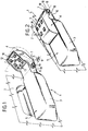
- Figure 1 is a perspective view of a preferred embodiment of an armrest according to the innovation, and
- Figure 2 illustrates the armrest in Figure 1 in a different working configuration, in perspective.
- In the appended figures 1 indicates an armrest which can be attached to a
panel 2 of the door of a vehicle (not illustrated), in particular to a panel of a motor vehicle door. -
Arm 1 comprises aposterior portion 3 supporting a forearm (not illustrated) of a user (not illustrated), and an anterior terminal portion 4 hinged to the said supportingportion 3. The latter is stably attached topanel 2, and is bounded at the top by asurface 5 which supports the forearm of the user and comprises afront appendage 6 bearing terminal hinged portion 4, which includes a fork 7, the arms 8 of which extend laterally on opposing sides of saidappendage 6. These arms 8 are hinged to appendage 6 to allow terminal portion 4 to rotate with respect to supportingportion 3 about ahorizontal axis 9 at right angles to a longitudinal axis ofarmrest 1 between a first extreme working position illustrated in Figure 1 in which terminal portion 4 extends longitudinally outward from supportingportion 3, and a second extreme working position illustrated in Figure 2 in which portion 4 is located above supportingportion 3 and is in contact withsurface 5 bounding saidportion 3. - As illustrated in Figure 1, terminal portion 4 is formed in such a way as to house a
first switch panel 10, which comprises a plurality ofrocker switches 12, and a corresponding plurality ofindicator lights 13. Each ofswitches 12 is capable of controlling a corresponding electrically driven component (not illustrated) of the motor vehicle (not illustrated), in particular theseswitches 12 are capable of controlling those components of the motor vehicle which under normal conditions of use are moved most frequently, such as e.g. the door windows (not illustrated). - When terminal portion 4 is placed in the first working position,
switch panel 10 forms an extension of supportingsurface 5, and in particular forms an obtuse angle with said supportingsurface 5, while when terminal portion 4 is placed in the second extreme workingposition switch panel 10 is located in a position facing supportingsurface 5 and substantially in contact therewith. - As illustrated in Figure 2, terminal portion 4 is also shaped in such a way as to house a second switch panel 15 which is located substantially on the opposite side of terminal portion 4 with respect to
first switch panel 10, and when same terminal portion 4 is placed in the second extreme working position it extends in the same direction as supportingsurface 5 and forms a substantially planar angle therewith. This switch panel 15 also comprises a plurality ofrocker switches 16, each of which is capable of controlling a corresponding electrically operated component (not illustrated) of the motor vehicle (not illustrated). In particular theseswitches 16 are capable of controlling those components of the motor vehicle (not illustrated) which under normal conditions of use are moved less frequently than the components controlled by theswitches 12 offirst switch panel 10. Forexample switches 16 are generally capable of controlling the adjustment of the front seats (not illustrated) of the vehicle, and/or the rear view mirrors (not illustrated) of the motor vehicle (not illustrated). - Again with reference to the appended figures, between supporting
portion 3 and terminal 4 there is placed a knownangular locking device 18 which can be operated by an operator and is capable of adopting a plurality of preferred angular positions (indicated by dotted and dashed lines in Figure 1) of terminal portion 4 with respect to supportingportion 3 between the said first and second extreme working positions. -
Device 18 comprises acontrol switch 19, operation of which by the user in the direction of arrow A (Figure 1) releasesportions 3 and 4 from their locked angular relationship. - In use, assuming for example that terminal portion 4 is located in the first working position and therefore is in the condition in which
switch panel 10 may be used, action onswitch 19 makes it possible to release terminal portion 4 from its linked angular relationship to supportingportion 3 and consequently to rotate terminal portion 4 aroundaxis 9 by substantially 180o to bring it into the second working position and therefore make second switch panel 15 accessible to the user. Alternatively, again starting from the condition in which terminal portion 4 is located in the first working position, it is possible byoperating switch 19 to rotate terminal portion 4 aboutaxis 9 in such a way as to vary the angular position offirst switch panel 10 with respect to supportingsurface 5 and adjustswitch panel 10 to the user's requirements. - From what has been described it is clear that
armrest 1 described above has the advantage that first of allfirst switch panel 10 controlling the components of the motor vehicle which are used with greater frequency can be adjusted to the users requirements, but also makes it possible to easily control those components of the said motor vehicle which are used less frequently than the former. In fact the structural characteristics ofarmrest 1 substantially make it possible for the switch panel to be changed over simply and immediately, and, in particular, this may be performed by the user even while driving the vehicle. - It is also clear that modifications and variants which do not go beyond the scope of the protection of this innovation may be made to armrest 1. In particular the manner in which terminal portion 4 is connected to supporting
portion 6 may be varied, and the position ofaxis 9 about which terminal portion 4 is rotated with respect to supportingportion 3 may also be varied. - Finally,
armrest 1 may not be of a type which is suitable for connection to theinner panel 2 of a door, but may be a common armrest adjacent to a user's seat and/or placed between two front or rear seats of the vehicle.
Claims (7)
- An armrest (1) for a vehicle comprising a portion (3) supporting the forearm of a user bounded at the top by a supporting surface (5) and a terminal portion (3) formed in such a way as to house a first switch panel (10) controlling at least one service in the vehicle, characterised in that the said terminal portion (4) is hinged to the said supporting portion (3) to rotate with respect to the said supporting portion (3) between a first extreme working position in which the said terminal portion (4) lies beyond the said supporting portion (3) and the said first switch panel (10) is located on the same side as the supporting surface (5), and a second extreme working position in which the said terminal portion (4) at least partly overlaps the said supporting portion (3) and the said first switch panel (10) is placed in a position facing the said supporting surface (5), the said terminal portion (4) being also formed so as to house a second switch panel (15) which is located substantially on the opposite side of the said terminal portion (4) with respect to the said first switch panel (10).
- An armrest according to claim 1, characterised in that the said terminal portion (4) is hinged to the said supporting portion (3) to rotate with respect to the latter and around an axis (9) which is substantially horizontal and at right angles to a longitudinal axis of the armrest (1).
- An armrest according to claim 1 or 2, characterised in that when the said terminal portion (4) is located in the said first extreme working position the said first switch panel (10) forms an obtuse angle with the said supporting surface and when the said terminal portion (4) is in the said second extreme working position the said second switch panel (15) faces the said part of the said supporting surface (5).
- An armrest according to any one of the foregoing claims, characterised in that between the said supporting portion (3) and the said terminal portion (4) there is located an angular locking device (18) which can be operated by an operator and which is capable of locking the said terminal portion (4) at an angle with respect to the said supporting portion (3) to define a plurality of preferred angular positions between the said portions (3), (4).
- An armrest according to claim 4, characterised in that the said lying device (18) includes an operating switch (19) which extends towards the interior of the passenger space of the said vehicle.
- An armrest according to any one of the foregoing claims, characterised in that the said first switch panel (10) comprises a plurality of rocker switches (12) controlling corresponding components of the vehicle which are moved with a relatively high frequency while the vehicle is in use, and the said second switch panel (15) comprises a plurality of rocker switches (16) controlling corresponding components of the vehicle which are moved less frequently than the component moved by the switches (12) of the said first switch panel (10).
- An armrest according to any one of the foregoing claims, characterised in that the said supporting portion (3) is stably attached to an inner panel (2) of a vehicle door.
Applications Claiming Priority (2)
| Application Number | Priority Date | Filing Date | Title |
|---|---|---|---|
| ITTO910254 | 1991-10-15 | ||
| ITTO910254U IT223321Z2 (en) | 1991-10-15 | 1991-10-15 | ARMREST FOR A VEHICLE. |
Publications (2)
| Publication Number | Publication Date |
|---|---|
| EP0537718A1 EP0537718A1 (en) | 1993-04-21 |
| EP0537718B1 true EP0537718B1 (en) | 1995-09-06 |
Family
ID=11409194
Family Applications (1)
| Application Number | Title | Priority Date | Filing Date |
|---|---|---|---|
| EP92117563A Expired - Lifetime EP0537718B1 (en) | 1991-10-15 | 1992-10-14 | Armrest for a vehicle |
Country Status (5)
| Country | Link |
|---|---|
| US (1) | US5286078A (en) |
| EP (1) | EP0537718B1 (en) |
| BR (1) | BR7201737U (en) |
| DE (1) | DE69204617T2 (en) |
| IT (1) | IT223321Z2 (en) |
Families Citing this family (29)
| Publication number | Priority date | Publication date | Assignee | Title |
|---|---|---|---|---|
| SE9300459L (en) * | 1993-02-12 | 1994-02-07 | Saab Automobile | Control module for servo-assisted window lifts in motor vehicles |
| US5448028A (en) * | 1993-12-10 | 1995-09-05 | Davidson Textron, Inc. | Armrest electrical switch arrangement with soft interior trim panel |
| JP3305489B2 (en) * | 1994-03-08 | 2002-07-22 | アルプス電気株式会社 | Switch device |
| IT232519Y1 (en) * | 1994-08-03 | 2000-01-10 | Borio Valerio | COMMAND GROUP FOR THE CONDUCT OF AN AGRICULTURAL TRACTOR |
| US5555172A (en) * | 1994-08-22 | 1996-09-10 | Prince Corporation | User interface for controlling accessories and entering data in a vehicle |
| DE19624463A1 (en) * | 1996-06-19 | 1998-01-02 | Fendt Xaver Gmbh & Co | Control device for commercial vehicles, in particular for agricultural tractors |
| DE19707477A1 (en) * | 1997-02-25 | 1998-08-27 | Bayerische Motoren Werke Ag | Back seat bench in a motor vehicle |
| US6065560A (en) * | 1998-03-16 | 2000-05-23 | Zf Meritor | Shift input module for automated manual shift system |
| DE10013054A1 (en) * | 2000-03-19 | 2001-09-27 | Am3 Automotive Multimedia Ag | Multi-media input device for use in vehicle with operating buttons/devices located at different parts of surface for finger or thumb operation |
| US6536825B2 (en) * | 2000-05-09 | 2003-03-25 | Lear Corporation | Control panel for a vehicle |
| US6820921B2 (en) | 2001-09-04 | 2004-11-23 | Lear Corporation | Control panel for a vehicle |
| US20040164577A1 (en) * | 2002-07-25 | 2004-08-26 | Shabana Mohsen D. | Adjustable armrest |
| DE60309302T2 (en) * | 2003-06-23 | 2007-02-15 | Caterpillar Inc., Peoria | Machine control device and method |
| US7178623B2 (en) * | 2003-12-19 | 2007-02-20 | Caterpillar Inc | Operator control assembly |
| US7497298B2 (en) | 2004-06-22 | 2009-03-03 | Caterpillar Inc. | Machine joystick control system |
| US7635045B2 (en) * | 2004-07-30 | 2009-12-22 | Caterpillar Inc. | Machine tool control console |
| US7458439B2 (en) * | 2004-08-31 | 2008-12-02 | Caterpillar Inc. | Machine control pedestal |
| FR2879805B1 (en) * | 2004-12-20 | 2007-02-16 | Renault Sas | DEVICE FOR CONTROLLING FUNCTIONS OF A MOTOR VEHICLE |
| US7712571B2 (en) | 2006-06-23 | 2010-05-11 | Caterpillar Inc. | Ergonomic machine control console |
| US8039769B2 (en) * | 2006-09-19 | 2011-10-18 | Deere & Company | Joystick deactivation |
| GB2458283A (en) * | 2008-03-12 | 2009-09-16 | Valtra Oy Ab | Vehicle armrest with stowable drivers interface |
| WO2010081142A1 (en) * | 2009-01-12 | 2010-07-15 | Fisker Automotive, Inc. | Glass interior trim member |
| RU2556802C2 (en) * | 2010-11-05 | 2015-07-20 | Вольво Констракшн Эквипмент Аб | Construction machine with improved ergonomics of control organs |
| US9370175B2 (en) | 2014-02-04 | 2016-06-21 | The Toro Company | Sprayer with easily locatable operational controls, hill assist, pivotal hose reel, and agitation boost |
| US9156387B2 (en) * | 2014-02-17 | 2015-10-13 | Ford Global Technologies, Llc | Coupling structure for pull-cup and armrest assembly |
| US20170015217A1 (en) * | 2014-03-12 | 2017-01-19 | Johnson Controls Technology Company | Deployable seat control interface mechanism |
| DE102018213769A1 (en) * | 2018-08-16 | 2020-02-20 | Audi Ag | Center console and motor vehicle |
| DE102020000729A1 (en) * | 2020-02-04 | 2021-08-05 | Man Truck & Bus Se | Arrangement of a palm rest and a control element for a vehicle |
| DE102020117691A1 (en) * | 2020-07-06 | 2022-01-13 | Grammer Aktiengesellschaft | Steering device for vehicles |
Family Cites Families (11)
| Publication number | Priority date | Publication date | Assignee | Title |
|---|---|---|---|---|
| US4180713A (en) * | 1975-06-25 | 1979-12-25 | Societe Anonyme Automobiles Citroen | Switch control unit for automobile vehicle |
| DE2723149C3 (en) * | 1977-05-23 | 1980-10-23 | Bremshey Ag, 5650 Solingen | Folding table on an armrest or a side cheek of a seat, in particular a rail vehicle seat |
| DE7717085U1 (en) * | 1977-05-28 | 1977-09-29 | Recaro Gmbh & Co, 7312 Kirchheim | VEHICLE SEAT |
| JPS5780935A (en) * | 1980-11-05 | 1982-05-20 | Niles Parts Co Ltd | Centralized control switch apparatus for vehicle |
| US4473724A (en) * | 1981-08-05 | 1984-09-25 | Kabushiki Kaisha Tokai Rika Denki Seisakusho | Movable element control arrangement |
| DE3148724A1 (en) * | 1981-12-09 | 1983-06-16 | Bayerische Motoren Werke AG, 8000 München | ELECTRICALLY ADJUSTABLE VEHICLE SEAT |
| DE8234397U1 (en) * | 1982-12-08 | 1983-06-09 | Dieter Gräßlin Feinwerktechnik, 7742 St Georgen | Electrical switch for room installation with electronic equipment |
| DE3445891A1 (en) * | 1984-12-15 | 1986-06-19 | Grundig E.M.V. Elektro-Mechanische Versuchsanstalt Max Grundig & Co KG, 8510 Fürth | DEVICE FOR REMOTE CONTROL OF SEVERAL AUDIO AND VIDEO DEVICES |
| DE3719105A1 (en) * | 1987-06-06 | 1988-12-22 | Keiper Recaro Gmbh Co | Aircraft passenger seat |
| JPH0646365Y2 (en) * | 1989-02-15 | 1994-11-30 | 小糸工業株式会社 | Armrest that houses the TV receiver |
| JPH0422288U (en) * | 1990-06-18 | 1992-02-25 |
-
1991
- 1991-10-15 IT ITTO910254U patent/IT223321Z2/en active IP Right Grant
-
1992
- 1992-10-13 US US07/960,550 patent/US5286078A/en not_active Expired - Fee Related
- 1992-10-14 DE DE69204617T patent/DE69204617T2/en not_active Expired - Fee Related
- 1992-10-14 EP EP92117563A patent/EP0537718B1/en not_active Expired - Lifetime
- 1992-10-14 BR BR7201737U patent/BR7201737U/en not_active Application Discontinuation
Also Published As
| Publication number | Publication date |
|---|---|
| DE69204617T2 (en) | 1996-03-21 |
| US5286078A (en) | 1994-02-15 |
| ITTO910254V0 (en) | 1991-10-15 |
| BR7201737U (en) | 1993-06-15 |
| EP0537718A1 (en) | 1993-04-21 |
| DE69204617D1 (en) | 1995-10-12 |
| IT223321Z2 (en) | 1995-06-21 |
| ITTO910254U1 (en) | 1993-04-15 |
Similar Documents
| Publication | Publication Date | Title |
|---|---|---|
| EP0537718B1 (en) | Armrest for a vehicle | |
| JP2004504983A (en) | Arrangement of operator control | |
| JPH11202960A (en) | Working machine lever support structure of working vehicle | |
| GB2313481A (en) | Control device for an air conditioning system of a motor vehicle | |
| US5508897A (en) | Overhead lamp assembly | |
| JP2002144937A (en) | Automobile power seat switch device | |
| EP2073233B1 (en) | Motor control device | |
| EP1726483B1 (en) | Outer rear-view mirror unit for a motor-vehicle with shape memory actuating means | |
| US20080012413A1 (en) | Seat Adjustment Mechanism Comprising a Rotative Actuating Element | |
| US6150620A (en) | Steering column switch for a motor vehicle | |
| JP3480148B2 (en) | Power window device for vehicles | |
| GB2333226A (en) | A vehicle seat assembly | |
| KR0157262B1 (en) | Movable console box attached power seat in a vehicle | |
| KR200144113Y1 (en) | Device for adjusting an angle of a door hand grip in an automobile | |
| EP0702385A1 (en) | Manual multi-function control device | |
| JPH10169309A (en) | Power window switch | |
| JPH07249348A (en) | Switch | |
| EP1003189A2 (en) | Power window control for motor vehicles | |
| KR101077442B1 (en) | Switching device for controlling side view mirrors of a vehicle | |
| JPS6177565A (en) | Steering device | |
| KR0132594Y1 (en) | Lumbar-supporter for installing in a seat back of an automobile | |
| KR100250087B1 (en) | Outside rear view mirror for vehicles | |
| JPH02103827A (en) | Double switch knob structure | |
| GB2133682A (en) | Multifunctional unit | |
| KR0123782Y1 (en) | Rear view mirror control switch with remote function in an automobile audio device |
Legal Events
| Date | Code | Title | Description |
|---|---|---|---|
| PUAI | Public reference made under article 153(3) epc to a published international application that has entered the european phase |
Free format text: ORIGINAL CODE: 0009012 |
|
| AK | Designated contracting states |
Kind code of ref document: A1 Designated state(s): DE ES FR GB SE |
|
| 17P | Request for examination filed |
Effective date: 19930727 |
|
| 17Q | First examination report despatched |
Effective date: 19941227 |
|
| GRAA | (expected) grant |
Free format text: ORIGINAL CODE: 0009210 |
|
| AK | Designated contracting states |
Kind code of ref document: B1 Designated state(s): DE ES FR GB SE |
|
| PG25 | Lapsed in a contracting state [announced via postgrant information from national office to epo] |
Ref country code: ES Free format text: THE PATENT HAS BEEN ANNULLED BY A DECISION OF A NATIONAL AUTHORITY Effective date: 19950906 |
|
| REF | Corresponds to: |
Ref document number: 69204617 Country of ref document: DE Date of ref document: 19951012 |
|
| ET | Fr: translation filed | ||
| PG25 | Lapsed in a contracting state [announced via postgrant information from national office to epo] |
Ref country code: SE Effective date: 19951206 |
|
| PLBE | No opposition filed within time limit |
Free format text: ORIGINAL CODE: 0009261 |
|
| STAA | Information on the status of an ep patent application or granted ep patent |
Free format text: STATUS: NO OPPOSITION FILED WITHIN TIME LIMIT |
|
| 26N | No opposition filed | ||
| REG | Reference to a national code |
Ref country code: GB Ref legal event code: IF02 |
|
| PGFP | Annual fee paid to national office [announced via postgrant information from national office to epo] |
Ref country code: GB Payment date: 20061018 Year of fee payment: 15 |
|
| PGFP | Annual fee paid to national office [announced via postgrant information from national office to epo] |
Ref country code: FR Payment date: 20061030 Year of fee payment: 15 |
|
| PGFP | Annual fee paid to national office [announced via postgrant information from national office to epo] |
Ref country code: DE Payment date: 20061130 Year of fee payment: 15 |
|
| GBPC | Gb: european patent ceased through non-payment of renewal fee |
Effective date: 20071014 |
|
| PG25 | Lapsed in a contracting state [announced via postgrant information from national office to epo] |
Ref country code: DE Free format text: LAPSE BECAUSE OF NON-PAYMENT OF DUE FEES Effective date: 20080501 |
|
| REG | Reference to a national code |
Ref country code: FR Ref legal event code: ST Effective date: 20080630 |
|
| PG25 | Lapsed in a contracting state [announced via postgrant information from national office to epo] |
Ref country code: GB Free format text: LAPSE BECAUSE OF NON-PAYMENT OF DUE FEES Effective date: 20071014 |
|
| PG25 | Lapsed in a contracting state [announced via postgrant information from national office to epo] |
Ref country code: FR Free format text: LAPSE BECAUSE OF NON-PAYMENT OF DUE FEES Effective date: 20071031 |