EP0537136A2 - Cathéter avec moyens de prévention d'occlusions et procédé d'utilisation d'un tel cathéter - Google Patents
Cathéter avec moyens de prévention d'occlusions et procédé d'utilisation d'un tel cathéter Download PDFInfo
- Publication number
- EP0537136A2 EP0537136A2 EP93100066A EP93100066A EP0537136A2 EP 0537136 A2 EP0537136 A2 EP 0537136A2 EP 93100066 A EP93100066 A EP 93100066A EP 93100066 A EP93100066 A EP 93100066A EP 0537136 A2 EP0537136 A2 EP 0537136A2
- Authority
- EP
- European Patent Office
- Prior art keywords
- lumen
- distal end
- catheter tube
- catheter
- end portion
- Prior art date
- Legal status (The legal status is an assumption and is not a legal conclusion. Google has not performed a legal analysis and makes no representation as to the accuracy of the status listed.)
- Granted
Links
Images


Classifications
-
- A—HUMAN NECESSITIES
- A61—MEDICAL OR VETERINARY SCIENCE; HYGIENE
- A61M—DEVICES FOR INTRODUCING MEDIA INTO, OR ONTO, THE BODY; DEVICES FOR TRANSDUCING BODY MEDIA OR FOR TAKING MEDIA FROM THE BODY; DEVICES FOR PRODUCING OR ENDING SLEEP OR STUPOR
- A61M25/00—Catheters; Hollow probes
- A61M25/01—Introducing, guiding, advancing, emplacing or holding catheters
- A61M25/0102—Insertion or introduction using an inner stiffening member, e.g. stylet or push-rod
-
- A—HUMAN NECESSITIES
- A61—MEDICAL OR VETERINARY SCIENCE; HYGIENE
- A61M—DEVICES FOR INTRODUCING MEDIA INTO, OR ONTO, THE BODY; DEVICES FOR TRANSDUCING BODY MEDIA OR FOR TAKING MEDIA FROM THE BODY; DEVICES FOR PRODUCING OR ENDING SLEEP OR STUPOR
- A61M25/00—Catheters; Hollow probes
- A61M25/0021—Catheters; Hollow probes characterised by the form of the tubing
- A61M25/0023—Catheters; Hollow probes characterised by the form of the tubing by the form of the lumen, e.g. cross-section, variable diameter
- A61M25/0026—Multi-lumen catheters with stationary elements
- A61M25/003—Multi-lumen catheters with stationary elements characterized by features relating to least one lumen located at the distal part of the catheter, e.g. filters, plugs or valves
-
- A—HUMAN NECESSITIES
- A61—MEDICAL OR VETERINARY SCIENCE; HYGIENE
- A61M—DEVICES FOR INTRODUCING MEDIA INTO, OR ONTO, THE BODY; DEVICES FOR TRANSDUCING BODY MEDIA OR FOR TAKING MEDIA FROM THE BODY; DEVICES FOR PRODUCING OR ENDING SLEEP OR STUPOR
- A61M25/00—Catheters; Hollow probes
- A61M25/0021—Catheters; Hollow probes characterised by the form of the tubing
- A61M25/0023—Catheters; Hollow probes characterised by the form of the tubing by the form of the lumen, e.g. cross-section, variable diameter
- A61M25/0026—Multi-lumen catheters with stationary elements
- A61M25/0032—Multi-lumen catheters with stationary elements characterized by at least one unconventionally shaped lumen, e.g. polygons, ellipsoids, wedges or shapes comprising concave and convex parts
-
- A—HUMAN NECESSITIES
- A61—MEDICAL OR VETERINARY SCIENCE; HYGIENE
- A61M—DEVICES FOR INTRODUCING MEDIA INTO, OR ONTO, THE BODY; DEVICES FOR TRANSDUCING BODY MEDIA OR FOR TAKING MEDIA FROM THE BODY; DEVICES FOR PRODUCING OR ENDING SLEEP OR STUPOR
- A61M25/00—Catheters; Hollow probes
- A61M25/0067—Catheters; Hollow probes characterised by the distal end, e.g. tips
- A61M25/0074—Dynamic characteristics of the catheter tip, e.g. openable, closable, expandable or deformable
- A61M25/0075—Valve means
-
- A—HUMAN NECESSITIES
- A61—MEDICAL OR VETERINARY SCIENCE; HYGIENE
- A61M—DEVICES FOR INTRODUCING MEDIA INTO, OR ONTO, THE BODY; DEVICES FOR TRANSDUCING BODY MEDIA OR FOR TAKING MEDIA FROM THE BODY; DEVICES FOR PRODUCING OR ENDING SLEEP OR STUPOR
- A61M25/00—Catheters; Hollow probes
- A61M25/01—Introducing, guiding, advancing, emplacing or holding catheters
Definitions
- THIS INVENTION relates generally to catheter slit -valves and catheters, catheters having slit valves and, more particularly, novel catheters, catheter slit valve having extraordinarily reliability and to multi-lumen catheter assemblies and relates methods.
- a single lumen has been used at the distal end of a catheter, with the single lumen being joined to multi-lumens disposed away from the distal end of the catheter.
- This approach undesirably co-mingles liquids within the single distal end lumen, and does not allow independent use, perhaps simultaneous independent use, of each of several lumens.
- distal end refers to the forward end of the catheter which is inserted into the patients's body.
- proximal end refers to the rearward end thereof which remains outside the patient's body.
- the present invention comprises catheter tubes of elastomeric material having novel lumen shapes which prevent occlusion and accommodate continued liquid flow even when inadvertently kinked during use.
- the present invention comprises catheter tube slit valves, the walls of which are mechanically weakened and which provide greater reliability, while avoiding the need for large pressure variations during use. Symmetrical and asymmetrical versions of said slit valve are provided.
- novel combinations of highly reliably slit valves and catheter tubes are provided by the present invention.
- the present invention also comprises sheathed independently operable multi-lumen catheter assemblies of elastomeric material, including ultra soft elastomeric material such as silicone rubber or polyurethane, wherein each lumen is independently operable and the distal end of at least one lumen is normally closed by a three-position slit valve disposed in an external covering or sheath laterally to one side of the lumen.
- the plurality of valve sites in the distal end portion of the external covering are disposed in spaced off-set relation.
- Each slit valve in the external covering normally closes the distal end of one lumen and comprises one or more two-way living hinges.
- the present invention provides multi-lumen catheters, and related methods, wherein each lumen-defining wall is selectively exposed, but concealed at the proximal and distal ends whereby, following placement of the distal end of the catheter tube in the vein of a patient, the unified proximal end of the tube may be manipulated, sometimes subcutaneously, with the exposed tubes ultimately being severed and each equipped with a connector for selective independent passage of influent and/or effluent liquid along each lumen.
- a further paramount object is the provision of a catheter tube having one or more lumens which are uniquely shaped so that occlusion of flow is prevented even when the catheter tube is inadvertently kinked.
- An additional object of importance is the provision of novel highly reliable catheter tube slit valves, which hingedly open and close without the need for chemically weakening of the material at the slit valve.
- Another dominant object is the provision of extraordinarily reliable slit valves in catheter tubes which avoid any need for large pressure variations during use.
- a further significant object is the provision of novel highly reliable mechanically hinged catheter tube slit valves.
- a further predominant object is the provision of novel highly reliable symmetrical and asymmetrical slit valves.
- An object of primary importance is the provision of novel catheter tubes and slit valve combinations.
- Another primary object of the present invention is the provision of sheathed multi-lumen catheters assemblies.
- a further important object of significance is provision of multi-lumen sheathed catheters wherein the distal end of each lumen is normally closed by a three-position slit valve.
- a further object of consequence is the provision of a multi-lumen catheter of synthetic resinous material wherein a three-position slit valve is disposed in an external covering at the leading end of each lumen.
- An additional paramount object of the present invention is the provision of a multi-lumen catheter of synthetic resinous material wherein the leading end of each lumen is closed by a three-position slit valve formed in an external covering, each slit valve comprising at least one two-way living hinge which is either eccentrically or symmetrically disposed.
- a further predominant object of the present invention is the provision of multi-lumen catheters, and related methods, wherein each lumen-defining tube is selectively exposed and concealed whereby a single external proximal end and a single external distal end are provided for placement purposes, following which the exposed walls forming the lumens can be severed and each receive a connector for independent use of each lumen.
- Figures 1-8 illustrate in transverse cross-section several catheter tubes embodying the principles of the present invention, each having one or more novel lumen shapes which prevent occlusion and accommodate continued liquid flow, even when inadvertently kinked, bent, twisted or collapsed.
- Figure 1 comprises a generally cylindrical catheter tube 30, formed of a body of elastomeric material 32 defining an outside smooth cylindrical surface 34 and a single D-shaped axial lumen 36.
- the lumen 36 comprises linear wall surfaces 38, 40 and 42.
- Linear wall surfaces 38 and 40 are joined tangentially by a small diameter fillet corner 44 and surfaces 38 and 42 tangentially by a small diameter fillet corner 46.
- Linear wall surfaces 40 and 42 are joined tangentially by an arcuate wall surface 48.
- the location and shape of the corners 44 and 46 define a relatively thin dimension 50 through the body 32, which makes the D-shaped lumen 36 amenable to utilisation of certain slit valves fashioned in accordance with the principles of the present invention, as hereinafter more fully described.
- the nature and shape of the lumen 36 has shown through experimentation to prevent occlusion of the lumen 36 of the catheter tube 30 when the same is kinked, bend, twisted or collapsed.
- catheter tubing according to the prior art which utilises the cylindrical exterior surface and one or more cylindrical internal hollow lumens will result in total occlusion of the lumen or lumens when such prior art catheter tubing is, for example, kinked upon itself through essentially 180 degrees.
- FIG. 2 The embodiment of Figure 2, generally designated 30′, is substantially identical in all respects to the catheter tubing 30 of Figure 1, except that the surfaces 40′ and 42′ are somewhat shorter in their transverse dimension than previously described wall surfaces 40 and 42.
- the non-occluding characteristic of catheter tubing 30 also exists when catheter tubing 30′ is used.
- catheter tubing 30 ⁇ ( Figure 1) is substantially similar to previously described catheter tubing 30 and 30′, identical numerals being used to identify substantially identical parts.
- Catheter tubing 30 ⁇ differs from catheter tubing 30 in that the flat wall surfaces 40 ⁇ and 42 ⁇ are of a substantially smaller width than wall surfaces 40 and 42.
- the fillet corners 44′ and 46′ are substantially larger in radius and arc distance than corners 44 and 46 and do not respectively join the adjacent wall surface tangentially.
- lumen 36 ⁇ is somewhat smaller than lumen 36 with modified corner structure at each end of the reduce size flat wall surface 38′.
- Figures 4-6 illustrate, respectively, double-lumen catheter tubes 52, 54 and 56.
- catheter tubes 52, 54 and/or 56 have physical pars corresponding to heretofore described catheter tubes 30, 30′ or 30 ⁇ , identical numerals are used on Figures 4-6 and no further description of those physical parts is deemed necessary to an understanding of the present invention.
- Catheter tube 52 comprises primary lumen 60 and secondary lumen 62, each of which define a relatively short distance 50 between an angular lumen corner and the external surface 34 of the catheter tube.
- the catheter tube 52 comprises an internal body of material 64 which defines and separates the two lumens 60 and 62.
- Lumen 60 comprises a centrally disposed flat wall surface 66 interposed between two other flat wall surfaces 68 and 70.
- Wall surface 66 joins wall surface 68 tangentially via corner 72 and wall surface 70 via corner 74.
- Catheter tube 52 further comprises a secondary lumen 62, as mentioned above, lumen 62 comprising heretofore described wall surface 30 and fillet corners 44 and 46 tangentially joining relatively small flat wall surfaces 40 ⁇ and 42 ⁇ to surface 38.
- Wall surface 40 ⁇ is joined angularly or non-tangentially at site 82 to a linear wall surface 84, which tangentially merges with an arcuate wall surface 86.
- Wall surface 42 ⁇ likewise joins a flat upwardly angularly directed wall portion 88 at fillet corner 90.
- Wall portion 88 merges tangentially with arcuate wall portion 86.
- catheter tube 52 provides two aligned lumens which provide the relatively short corner spaces 50 to accommodate utilisation of highly reliable slit valves as hereinafter more fully explained and which, when the catheter tube 52 is kinked upon itself, will still accommodate liquid flow, as mentioned above.
- Double lumen catheter tube 54 is illustrated in Figure 5.
- Tube 54 provides internal body and wall structure 64 which provides for separate definition of the two spaced lumens 36′.
- These lumens while being somewhat different in size, are substantially identically shaped and each corresponds substantially to the lumen 36′ of Figure 2 already described.
- Catheter tube 56 ( Figure 6) comprises a primary D-shaped lumen 92 and a secondary D-shaped lumen 62.
- Lumen 92 is substantially identical to previously described lumen 36 ⁇ , except that rounded corners 44′ and 46′ are replaced by diagonally disposed non-tangential wall surfaces 94 and 96, respectively.
- Diagonal wall surface 94 joins wall surface 40 ⁇ at angular corner 98 and surface 38′ at angular corner 100.
- diagonal wall surface 96 joins wall surface 42 ⁇ at angular corner 102 and wall surface 38′ at angular corner 104.
- Lumen 62 was heretofore described in connection with catheter tube 52. See Figure 4.
- the non-occluding catheter tubes according to the present invention may comprise more than two lumens defined within the catheter.
- Figures 7 and 8 illustrate catheter tubes embodying the present invention which comprise three lumens, respectively.
- the catheter tube of Figure 7 is generally designated 106 and the tri-lumen catheter of Figure 8 is designated generally as 108.
- Catheter tube 106 comprises one primary and two secondary lumens 36 ⁇ .
- Catheter tube 38′ was described earlier in conjunction with in Figure 2. Accordingly, no further description is deemed necessary in respect to the lumen of catheter tube 106, except to say that the lumens are illustrated as being disposed, respectively, along predetermined radial lines, consistent with the requirements of structural integrity needed for indwelling catheters and so as to provide corner sites 50.
- catheter tube 108 comprises one primary and two secondary lumens 62, previously described in conjunction with catheter 56, shown in Figure 6. No further description is, therefore, deemed necessary, it being understood that the lumens 62 of catheter tube 108 are illustrated as being arranged along predetermined radial lines so that the corners 44 and 46 thereof create corner sites at locations 50.
- novel lumen shapes of catheter tubes embodying the present invention prevent occlusion of the lumens where the catheter tube is kinked, flattened, or the like, the novel lumens have been found to aid materially in the provision of novel slit valves according to the invention.
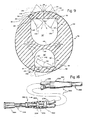
- Figure 9 shows the distal end portion of two-lumen catheter 54, described earlier in conjunction with Figure 5 and having D-shaped primary and secondary lumens 36′.
- the distal end portion of the tube 54 comprises exterior covering 32 and internal wall structure 64, which defines the lumens 36. Corners 44 and 46 of the lumens 36′ are located closer to the exterior covering surface 34 than any other part of the lumens 36′. Thus, corners 44 and 46, in each case define two hinge or fold lines or regions 50 where the catheter wall is thinnest. Relatively thicker areas 136 are disposed between hinge sites 50.
- the slit 138 of slit valve 35 is symmetrically disposed along a radial line equidistant between the hinge sites 50 of the primary lumen 36′.
- the D-shaped lumens 36′ are structurally stronger than conventional round catheter tube lumens. Therefore, lumens according to the present invention are more resistant to collapse under high negative pressures.
- the D-shaped lumens also offer two pincipal advantages in the operation of the valve 35. First, the thicker walls adjacent the self sealing slit 138 create a larger sealing surface area for the valve lips 136, and, therefore, create a more positive seal when the distal end portion of tube 54 is indwelling and under normal physiological pressures. Second, the flex of the valve 35 is concentrated at the hinge sites 50, which sites are located some distance from the slit 138.
- This concentration of the flex in a relatively small hinge site provides for more consistent operation, more reliable response to predetermined pressure differentials designed to open and close the valve, a wider valve opening, and a longer life of the valve 35.
- the use of thickened valve lips 136 also serves to raise the withdrawal threshold, providing for a more positive, highly reliable valve action.
- FIG. 9 also diagrammatically illustrates an eccentric slit valve 35′ comprising a single slit 141 disposed in one corner 46 of the secondary lumen 36′.
- the hinge action is concentrated at the single hinge site 141, illustrated at intersecting the other lumen corner 44.
- the entire asymmetrical valve lip 142 is hingedly displaced, inwardly or outwardly, to create the valve orifice.
- This eccentric configuration accommodates, with high reliability, use of the slit valve 141 in catheters having lumen sized too small to provide consistent operation of a symmetrical slit valve.
- the two slit valves illustrated in Figure 9 are shown, for ease of illustration, as being in the same transverse plane. However, in actual fabrication the slit valves are preferably longitudinally and radially offset each from the others. In limited testing to date, the eccentric valve 35′ has proved better in use than concentric valve 35, where the catheter lumen size was relatively small.
- the present invention embraces the aforedescribed slit valves comprising one or more mechanically weakened hinge regions independent of whether the wall regions of the slit valves are or are not chemically treated.
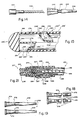
- Figure 10 shows the catheter 230 to comprise several major parts: i.e. 1) a distal end portion 232, adapted for insertion into a vein or other body cavity of a medical patient and comprising an exposed external sheath or covering 233 and internal wall structure 255, which defines a plurality of independent and separately operable circular lumens for carrying liquids to or from a desired body cavity; 2) a three-position pressure activated slit valve 234 forming a normally closed lateral gate or port shown as being disposed at the distal end of each catheter lumen, each slit valve 234 being controlled by the application of positive or negative pressures to the associated lumen of the catheter 230; 3) a coupling or transitional member 236 connecting the distal end portion 232 to a proximal end portion 237 which comprises a number of lumen-defining tubes 238; 4) the proximal end portion 232 and a distal end portion 232, adapted for insertion into a vein or other body cavity of a medical patient and comprising an
- Each three-way valve 234 normally prevents flow but provides for selective positive control of the liquid flow only through the associated lumen.
- a desired liquid is infused into the vein of a patient by forcing the associated valve 234 to hingedly open.
- a negative pressure liquid within a body cavity is withdrawn. Under normal physiological pressures, the valve 234 will remain closed and sealed.
- the distal end portion 232 is typically cylindrical in shape, as shown in Figure 11. However, the exterior surface may take other forms.
- the distal end portion 232 is preferably slender in diameter, allowing the closed distal tip 242 to be facilely introduced into a vein or other cavity and advanced to a desired treatment location, while the proximal end 237 remains outside the body.
- the length of the distal end portion 232 will, therefore, vary with its intended application.
- the distal end portion 232 is illustrated as having a uniform through relatively small exterior diameter so that it can be readily inserted into a vessel, such as the subclavian vein, without causing undue trauma to the patient. Typically, this requires that the distal end portion 232 have an outside diameter not exceeding about 0.125 inches (0.318 cm).
- the distal tip 242 of the distal end portion 32 is preferably dome-shaped and smoothed to further minimize trauma.
- the array of all valves 234 is formed in the sheath 233 and exposed at the exterior cylindrical surface 248 thereof, at site 243.
- Each valve 234 is also exposed laterally to one of the lumens, at sites 245.
- the valve sites are radially distributed in offset relation around the distal end portion 232 near the tip 242 so that no two valves 234 lie in any one radial plane.
- the valves 234 are also longitudinally separated or offset in their placement at relatively short but different distances from the distal tip 242 so that no two valves 234 lie in any one axial plane.
- valves 234 helps avoid structural weakness and helps prevent possible contamination of an influent sample withdrawn from one valve 234 by an infusion stream of effluent liquid from another valve 234 passing into the vein of a patient, which might adversely affect test results or result in premature mixing of incompatible therapeutic liquids. lt should be noted that longitudinal separation should not be used where the effect would be to position any valve 234 out of the desired treatment or exposure area.
- the distal end portion 232 is made of a durable and pliable yet shape-retaining biocompatible synthetic elastomeric material. It is presently preferred that the material comprise an ultra soft synthetic material. Typically, such material should have a hardness of less than 100 durometer and an elongation percentage of up to 700. A preferred material is a silicone rubber tubing having a hardness of about 59 durometer sold under the trade name SILASTIC by Dow Corning Co., Midland, Michigan.
- the distal end portion 232 is preferably at least partially radiopaque so that its precise position in the body may be radiogically verified. Tubes 237 are preferably transparent so that the physician can visually determine the presence of air bubbles, blook, or other liquids in each of the lumens during and after insertion.
- three independent lumens 252, 253 and 254 are longitudinally disposed inside the distal end external covering 233, the lumens typically being radially distributed at predetermined angles beneath the exterior cylindrical surface 248 of the distal end portion 232 in such a way that an interior lumen wall surface passes within a relatively short distance of the exterior surface 248 of the exterior covering 233, as measured along a radial line passing through the centre of each lumen 252, 253 and 254. It is apparent from the radial disposition of the lumens in close proximity to the exterior surface 248 that valve 234 installed along a radial line in the fashion just described or installed in any consistent position relative to the lumens 252, 253 and 254 will necessarily be radially separated from each other as previously discussed.
- Interior walls 255 ( Figure 11) respectively form and define the size and shape of the lumens 252, 253 and 254 at the distal end portion 232.
- Tubular, hollow walls 257 respectively form and define the size and shape of lumens 252, 253 and 254 at the proximal end portion 237.
- Proximal end portion 232′ comprises primary lumen 252 and secondary lumen 253′.
- Each lumen 252, 253 and 254 extends from the associated hub 240 at the proximal end portion 237 to a point near the distal tip 242. See Figure 10.
- the larger or primary lumen 252 extends substantially the entire length of the catheter 230, terminating in a closed tip wall portion 262 adjacent the distal tip 242 of the distal end portion 232. See Figure 13.
- Secondary lumen 253 and 254 terminate in a similar closed end wall portions 263, only one of which is illustrated in Figure 13.
- the lumens terminate at relatively short but different distances from the distal tip 242, for the purpose of providing longitudinal separation of the valves 234, as previously described.
- the proximal end portion 232 is preferably formed by extrusion, for reasons of simplicity and ease of construction, but other methods may be used.
- the lumens 252, 253 and 254 and the interior walls 255 forming the lumens 252, 253 and 254 are continuously formed during extrusion; thus, each lumen is of a uniform cross-sectional shape, being cylindrical or circular in the embodiment of Figures 10, 11 and 13.
- the closed end wall portions or plugs 262 and 263 are formed by injecting a suitable silicone rubber adhesive or the like into the leading ends of lumens 252, 253 or 254 for the distance from the distal tip 242.
- the adhesive then hardens to form the closed end wall portions or plugs 262 and 263, each up to the leading edge of the associated valve 234. If a radiopaque distal tip 242 is desired, this may be accomplished by mixing a radiopaque material with the adhesive prior to injection to form plugs 262 and 263.
- One three-position valve 234 is placed in the covering adjacent to and laterally interfacing with each lumen 252, 253 and 254 adjacent the plug 262 or 263.
- Each valve 234 is formed by a single relatively short slit 266 in the covering 233.
- Each slit extends longitudinally along the exterior of covering 233 parallel to but offset from the axis of the distal end portion 232.
- the thickness of each slit valve 234 is equal to the thickness of covering 233, so as to provide for selective liquid communication between the interior of the lumen 252, 253 and 254 with the exterior of the distal end portion 232.
- Each slit valve 234 is illustrated as being radially directed and symmetrically disposed in its corresponding lumen 252, 253 and 254 at the thinnest point in the covering 233.
- each slit valve 234 comprises two valve lips or walls 270 which comprise blunt edges. These edges contiguously mate and seal along the slit 266 under normal indwelling pressure conditions.
- Figure 11 shows the operation of each three-position slit valve 234.
- the valve wall Upon application of a predetermined pressure differential between the interior and exterior of the distal end portion 232, the valve wall will hingedly deflect or flex causing the valve lips 270 to separate at slit 266, creating a flow path-defining orifice through which liquid may pass in or out of the selected catheter lumen 252, 253, 254, when the distal end portion 232 is indwelling.
- the infusion threshold When the indwelling pressure inside the selected catheter lumen 252, 253, 254 extends the indwelling pressure outside the distal end of the catheter by a predetermined amount (the “infusion threshold"), the valve immediately surrounding the slit 266 deforms, and the lips 270 of the valve 234 are caused to separate hingedly in an outward direction thereby creating an orifice through which liquid is infused into the bloodstream, as shown in Figure 11. likewise, the application of a sufficient degree of negative pressure (the “windrawal threshold") to the selected catheter lumen 252, 253, 254 will cause the valve lips 270 to flex hingedly inwardly, also as shown in Figure 11, allowing withdrawal of blood or other fluids from the bloodstream or other by cavities.
- the windowrawal threshold a sufficient degree of negative pressure
- each slit valve 234 remains closed and sealed, as shown in solid lines in Figure 11. This requires that the catheter tube have sufficient memory to return to the closed sealed edge-to-edge position when liquid flow conditions terminate.
- the withdrawal threshold must also be high enough to prevent back bleeding under normal systolic pressures in the circulatory system of a patient.
- the infusion threshold must likewise be high enough to overcome the nromal venturi effect of blood flowing past the indwelling valve 234. The infusion and withdrawal threshold should not be so high as to make infusion or withdrawal difficult.
- Both the infusion and the withdrawal thresholds can be adjusted either by controlling the thicknness and configuration of the valve walls or lips 270 or by selectively treating the valve walls with a biocompatible softening agent such as dimethylsiloxane, as is more completely disclosed in U.S. Patent Application Serial No. 491,258, filed May 3, 1983.
- a biocompatible softening agent such as dimethylsiloxane
- the valve 234 may, if desired, be treated with an anticoagulant, such as Heparin.
- an anticoagulant such as Heparin.
- the design of the catheter 230 disclosed herein does not require such treatment.
- the liquid flow capacity of the lumens may vary with the intended application of the catheter 230.
- the lumens must, of course, be large enough to accommodate the desired fluid flow, while the thickness of the walls forming the lumens must be adequate to prevent rupture or inadvertent puncture and consequent leakage either between lumens or to or from the exterior.
- the slit valve 234 must be the weakest point in each lumen 252, 253 and 254. Each part of each catheter lumen must be stronger and more rigid than the valve lips 270, since collapse or rupture of any other part of the catheter would defeat the purpose of the catheter 230. It is, therefore, important that the lumen walls be strong enough to stand the full range of lumen pressure without rupture, inward collapse or other failure, which would impair proper operation of the slit valves 234.
- the distal end portion 232 can be otherwise fabricated.
- the distal end 232 ⁇ may comprise separate spaced lumen-defining tubes 274, 276 disposed within a hollow cavity 278 of an external thin walled cylindrical sheath or covering 233′, which has a smooth cylindrical exterior surface 248′.
- the proximal edges of the tubes 274, 276 are secured by satisfactory adhesive to the interior of the sheath 233′ at sites 280.
- the resulting lumens 252′ and 253 ⁇ respectively transversely interface with a slit valve 234 disposed in the wall of the sheath 233′.
- a slit valve 234 disposed in the wall of the sheath 233′.
- the distal tip 242′ of the distal end portion 232 ⁇ is configured so as to be shaped substantially the same as the heretofore described distal tip 242.
- the tip 242′ does provide an internal circular transverse flat wall 283 against which an insertion stylet or insertion stiffener abuts when placed within the primary lumen 252′, in a manner and for purposes hereinafter more fully described.
- Tubes 238 may be made of an ultra-soft synthetic material or other elastomer, similar to the material of the distal end portion 232, previously described. However, the tubes 238 must be strong enough to resist collapse or rupture and the additional environmental hazrds of an exposed tube. Each tube 238 may, therefore, be strengthened by using a tubing with thicker walls and/or a higher durometer. Tubes 238 are preferably at least partially transparent or translucent to accommodate visual monitoring of the contents therein. Unlike distal end portion 232, however, the proximal tubes 238 have no need for radiopacity, because they are not intended to be indwelling.
- Tubes 238 are most economically constructed of a tubing with concentric inner and outer cylindrical wall surfaces, thereby forming walls of uniform thickness providing a predetermined inside diameter equal to that of lumens, 252, 253 and 254 of distal end portion 232.
- the outside diameter of connector tubes 238 should be large enough provide a wall thickness at 257 adequate to resist abrasion and puncture.
- the trailing edge of each tube 238 is preferably perpendicular to the axis thereof. This accommodates connection of hub 240 at short hollow shaft 282 thereof, using a sleeve coupling 284. See Figures 11 and 14. Each sleeve coupling may be secured in the stated and illustrated position using conventional material-shrinkage techniques.
- the connector 236 is constructed by permanently connecting each lumen 252, 253 and 254 to one of the tubes 238 by use of a hollow coupling tube 285. See Figure 20.
- Each coupling tube 285 may be made of surgical steel, although other materials can be used.
- each coupling tube 285 has an inside diameter substantially the same as the inside diameter of the catheter lumen 252, 253, 254, to which it is attached so as to minimize if not prevent any flow restriction at the connector 236.
- the outside diameter of each coupling tube 285 should, therefore, be slightly larger than the inside diameters of lumens 252, 253, 254 and tubes 238.
- each tube 285 is force fit into lumens 252, 253, 254 at the body of connector 236, expanding each at the insertion sites.
- the leading end 297 of each tube 238 is force fit over the trailing end of the associated connector tube 285. See Figure 21.
- the entire joint or connector 236 is preferably secured with silicone rubber adhesive 264 or other appropriate sealant, and finally shrink-wrapped by soaking a tubular silicone rubber sleeve 296 in Freon or other solvent material causing it to temporarily expand, and slipping the sheath 296 over the connector 236. As the solvent evaporates the sheath 296 permanently contracts firmly around the remainder of the connector 236, adhering to the adhesive 264 and forming a secure and protected joint.
- Suture wing 298 is illustrated as being attached to the connector 236 so that the catheter 230 at connector 236 may be sutured in placed after the distal end thereof is indwelling.
- the suture wing 298, shown in Figures 10, 20 and 21 is fashioned from a small piece of silicone rubber sheet cut in the illustrated elongated shape and having circular holes 300 disposed in the ends thereof to receive sutures.
- Suture wing 298 may also help to prevent the catheter 230 from rolling or shifting when taped in place on a patient as opposed to suturing in place
- the suture wing 298 is preferably attached to the connector 236 using silicone rubber adhesive or another suitable method.
- a stylise or inserter 306 is preferably used to rigidify the distal end portion 232 during insertion.
- stylet 306 is illustrated as being formed of twisted surgical grade wire.
- the stylet 306 is illustrated as being equipped with an integral proximal hub 307, by which the stylet is manipulated. See especially Figures 13 and 14. It could also be formed of any yieldable and shape retaining biologically inert material such as polypropylene.
- Stylet 306 is preferably inserted into the primary lumen 252, until its distal tip 308 abuts the closed wall 262.
- a force manually applied to the stylet 306 causes the distal end thereof 308 to push against closed end 262 of the primary lumen 252. This places the covering 233 under tension, causing the distal end portion 232 to be pulled forward into the vein of the patient, for example.
- Primary lumen 252 must naturally be dimensioned large enough to accommodate the stylet 306.
- the walls 255 defining the primary lumen 252 and the covering 233 should also be thick enough to prevent accidental penetration by the stylet 306, which could result in undesired communication be tween lumens or trauma to the patient.
- the stylet tip 308 should also be constructed to prevent penetrating the primary lumen 252 through the slit valve 234 or through the tip or head 242.
- the abutment 262 of primary lumen 252 may be formed a sufficient distance from the slit valve 234 to allow an adequate safety margin against stylet damage at the valve site 234.
- the distal tip 308 of stylet is kept in constant pressure contact with the abutment 262 of primary lumen 252, during storage and insertion, as shown in Figure 13.
- the stylet 306 is slightly longer overall length than the primary lumen 232, so that the distal tip 308 of stylet 306 not only abuts the distal closed end 262 of the primary lumen 252, but the stylet hub 307 is exposed beyond the terminal hub 240 in the fully assembled condition.
- a tension is created in the distal end portion 232 and the remainder of the catheter 230 by the forced engagement of the distal tip 308 of the stylet 306 against the distal closed end 262 of the primary lumen 252.
- each three-position valve 234 may be selected to meet the needs of any particular application. In respect to the embodiment of Figures 10-15 and 21, this may be done chemically, as previously described. In the case of the embodiment of Figures 109, it is accomplished mechanically by providing a weakened hinge or fold line in the covering of the catheter tube. It is also to be noted that while the mechanically hinged valve is of particular importance in multi-lumen catheters, the principles thereof, comprising part of the present invention, also apply to single-lumen catheters.
- the lumens 252, 253, 254 have a circular cross-section. Because of the convex curve of the valve wall 268, the valve lips 270 flex somewhat more easily outwardly than inwardly. As a result, the withdrawal threshold is typically somewhat higher than the infusion threshold. Because the exterior surface 248 of the covering 233 is not concentric with respect to the curvature of the lumens 252, 253, 354, the valve wall lips 270 increase in thickness with distance from either side of the slit 266. As a result, the valve 234 requires higher pressure differentials to open fully than it does to merely break the seal at the slit. By modifying the dimensional relationship between the inside walls 255 defining the interior lumens 252, 253, 254 and the outside sheath surface 248 different valve threshold pressures and operating charcteristics may be obtained.
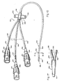
- FIGs 16-19 illustrate another presently preferred embodiment of the present invention, namely a two-lumen catheter generally designated 350 in Figure 16, constructed in accordance with the present invention for long term indwelling use with a patient.
- a trocar (not shown), for example may be used to position most of the proximal end of the catheter 350 subcutaneously as hereinafter explained in greater detail.
- the construction of the catheter 350 is essentially the same in many respects to the catheter 230. Therefore, only the differences will be described.
- the catheter 350 at the proximal end portion 352 thereof comprises two lumen-defining tubes 238.
- the tubes 238 do not each terminate in hubs 240 as with catheter 230 of Figure 10. Rather, the two tubes 238 are collectively joined to a common hub structure 354.
- Figure 16 shows the presently preferred construction of the proximal common hub 354.
- the tubes 238 are brought together into side-by-side contiguous relation with their blunt trailing ends 356 aligned.
- the leading blunt end 358 of a single short cannula 360 of hub structure 354 is placed in close proximity to and generally in alignment with the blunt ends 356 of tubes 238.
- a suitable silicone rubber adhesive is extruded over the ends 356 and 358.
- a cylindrical sleeve 362 is diametrically expanded by soaking it in freon, as previously described, and positioned over the joint so as to shrink into form contact with the adhesive and thus tightly seal the joint at either end.
- the common cannula 360 is fitted at its proximal end with a stylet hub 364 to which a stylet of the type previously disclosed is attached.
- the use of the stylet hub 364 connected to the common cannula 360 offers the advantage of being able to simultaneously flush all of the lumens comprised in the interior of the tubes 238 of the catheter 350 from a single syringe (not shown) or the like.
- the stylet hub 364 and the attached stylet are removed from the proximal end.
- a trocar (not shown) is conventionally releasably attached to the cannula 360. The trocar and the attached cannula 360 are then passed subcutaneously through the body to a convenient exit site.
- each severed end 372 of each tube 238 is thereafter fitted with a permanent terminal hub 374 by any suitable method.
- One such method is essentially disclosed in existing U.S. Patent No. 4,547,194.
- the method illustrated in Figures 18 and 19 comprises provision of the terminal hubs 374 which respectively comprise a hollow shaft 376.
- the outside diameter of the short shaft 376 is illustrated as being substantially the same as the outside diameter of the tube 238.
- the hubs 374 can be plugged with conventional plugs (not shown), the hubs during use, can be connected, for example, to an artificial kidney machine whereby blood from the subclavian vein, for example, can be removed through one tube 238 for processing through the artificial kidney machine and the effluent from the machine can be returned to the bloodstream through the other tube 238.
Applications Claiming Priority (3)
| Application Number | Priority Date | Filing Date | Title |
|---|---|---|---|
| US915474 | 1986-10-06 | ||
| US06/915,474 US4753640A (en) | 1986-10-06 | 1986-10-06 | Catheters and methods |
| EP87308731A EP0263645B1 (fr) | 1986-10-06 | 1987-10-01 | Cathéter |
Related Parent Applications (2)
| Application Number | Title | Priority Date | Filing Date |
|---|---|---|---|
| EP87308731A Division EP0263645B1 (fr) | 1986-10-06 | 1987-10-01 | Cathéter |
| EP87308731.6 Division | 1987-10-01 |
Publications (3)
| Publication Number | Publication Date |
|---|---|
| EP0537136A2 true EP0537136A2 (fr) | 1993-04-14 |
| EP0537136A3 EP0537136A3 (en) | 1993-07-07 |
| EP0537136B1 EP0537136B1 (fr) | 1998-12-23 |
Family
ID=25435809
Family Applications (2)
| Application Number | Title | Priority Date | Filing Date |
|---|---|---|---|
| EP87308731A Expired - Lifetime EP0263645B1 (fr) | 1986-10-06 | 1987-10-01 | Cathéter |
| EP93100066A Expired - Lifetime EP0537136B1 (fr) | 1986-10-06 | 1987-10-01 | Tube de cathéter |
Family Applications Before (1)
| Application Number | Title | Priority Date | Filing Date |
|---|---|---|---|
| EP87308731A Expired - Lifetime EP0263645B1 (fr) | 1986-10-06 | 1987-10-01 | Cathéter |
Country Status (7)
| Country | Link |
|---|---|
| US (1) | US4753640A (fr) |
| EP (2) | EP0263645B1 (fr) |
| JP (2) | JP2533897B2 (fr) |
| AU (1) | AU607155B2 (fr) |
| CA (1) | CA1319305C (fr) |
| DE (2) | DE3786441T2 (fr) |
| ES (1) | ES2005373A6 (fr) |
Cited By (6)
| Publication number | Priority date | Publication date | Assignee | Title |
|---|---|---|---|---|
| WO1994028961A1 (fr) * | 1993-06-03 | 1994-12-22 | Med-Pro Design, Inc. | Catheter a plusieurs lumieres |
| WO1995005864A1 (fr) * | 1993-08-27 | 1995-03-02 | Government Of The United States Of America, Represented By The Secretary Of The Department Of Health And Human Services | Systeme d'administration de medicament amelioree par convexion |
| WO1998032480A1 (fr) * | 1997-01-29 | 1998-07-30 | Baxter International Inc. | Configuration de tubage a deux lumieres pour catheter |
| US7871827B2 (en) | 2001-12-20 | 2011-01-18 | 3M Innovative Properties Company | Methods and devices for removal of organic molecules from biological mixtures using anion exchange |
| US9889277B2 (en) | 2005-01-13 | 2018-02-13 | Avent, Inc. | Tubing assembly and signal generator placement control device and method for use with catheter guidance systems |
| US9918907B2 (en) | 2011-09-08 | 2018-03-20 | Avent, Inc. | Method for electromagnetic guidance of feeding and suctioning tube assembly |
Families Citing this family (131)
| Publication number | Priority date | Publication date | Assignee | Title |
|---|---|---|---|---|
| US4737152A (en) * | 1986-07-02 | 1988-04-12 | Becton, Dickinson And Company | Catheter assembly |
| CA1330285C (fr) | 1987-12-22 | 1994-06-21 | Geoffrey S. Martin | Catheter a triple voie |
| JPH01308522A (ja) * | 1988-06-06 | 1989-12-13 | Sumitomo Electric Ind Ltd | 診断治療用カテーテル |
| US5201317A (en) * | 1988-06-06 | 1993-04-13 | Sumitomo Electric Industries, Ltd. | Diagnostic and therapeutic catheter |
| US4857054A (en) * | 1988-07-15 | 1989-08-15 | Eastman Kodak Company | Perfusion angioplasty catheter with pump assist |
| DE69028292T2 (de) * | 1989-02-02 | 1997-01-23 | Univ Minnesota | Einlumiger zweiwegkatheter mit rückschlagventil |
| US5290263A (en) * | 1989-02-02 | 1994-03-01 | Regents Of The University Of Minnesota | Bidirectional check valve catheter |
| US5009636A (en) * | 1989-12-06 | 1991-04-23 | The Kendall Company | Dual-lumen catheter apparatus and method |
| US5113911A (en) * | 1989-12-11 | 1992-05-19 | Advantec Corp. | Pressure actuated elastomeric valve |
| US5374245A (en) | 1990-01-10 | 1994-12-20 | Mahurkar; Sakharam D. | Reinforced multiple-lumen catheter and apparatus and method for making the same |
| US5221255A (en) | 1990-01-10 | 1993-06-22 | Mahurkar Sakharam D | Reinforced multiple lumen catheter |
| US5059170A (en) * | 1990-02-02 | 1991-10-22 | Mallinckrodt Medical, Inc. | Connection adapter for catheters |
| US5092844A (en) * | 1990-04-10 | 1992-03-03 | Mayo Foundation For Medical Education And Research | Intracatheter perfusion pump apparatus and method |
| US5169393A (en) * | 1990-09-04 | 1992-12-08 | Robert Moorehead | Two-way outdwelling slit valving of medical liquid flow through a cannula and methods |
| US5201722A (en) * | 1990-09-04 | 1993-04-13 | Moorehead Robert H | Two-way outdwelling slit valving of medical liquid flow through a cannula and methods |
| US5205834A (en) * | 1990-09-04 | 1993-04-27 | Moorehead H Robert | Two-way outdwelling slit valving of medical liquid flow through a cannula and methods |
| US5250034A (en) * | 1990-09-17 | 1993-10-05 | E-Z-Em, Inc. | Pressure responsive valve catheter |
| US5120316A (en) * | 1990-09-28 | 1992-06-09 | Akzo N.V. | Urethral catheter and catheterization process |
| US5163921A (en) * | 1990-10-04 | 1992-11-17 | Feiring Andrew J | Valved perfusion cardiovascular catheters |
| US5186715A (en) * | 1990-12-06 | 1993-02-16 | E-Z-Em, Inc. | Biliary drainage method |
| FR2671283B1 (fr) * | 1991-01-08 | 1995-05-12 | Alain Durand | Catheter multilumiere intravasculaire, susceptible d'etre implante avec tunnellisation. |
| CA2062000A1 (fr) * | 1991-03-07 | 1992-09-08 | H. Robert Moorehead | Catheter renforce et methodes de fabrication et d'utilisation du catheter renforce |
| US5147332A (en) * | 1991-05-17 | 1992-09-15 | C.R. Bard, Inc. | Multi-valve catheter for improved reliability |
| US5112301A (en) * | 1991-06-19 | 1992-05-12 | Strato Medical Corporation | Bidirectional check valve catheter |
| US5215527A (en) * | 1991-12-12 | 1993-06-01 | Becton, Dickinson And Company | Catheter introducer assembly |
| US5207649A (en) * | 1991-12-13 | 1993-05-04 | Brigham And Women's Hospital | Introducer sheath having a hemostatic closure |
| US5221256A (en) * | 1992-02-10 | 1993-06-22 | Mahurkar Sakharam D | Multiple-lumen catheter |
| US5221278A (en) * | 1992-03-12 | 1993-06-22 | Alza Corporation | Osmotically driven delivery device with expandable orifice for pulsatile delivery effect |
| US5224938A (en) * | 1992-03-18 | 1993-07-06 | Strato Medical Corporation | Valved catheter |
| US5271414A (en) * | 1992-09-30 | 1993-12-21 | Becton, Dickinson And Company | Biopsy cannula having non-cylindrical interior |
| GB2274991B (en) * | 1993-02-11 | 1996-10-30 | Sara Kinal | Embryo replacement catheter |
| US5308338A (en) * | 1993-04-22 | 1994-05-03 | Helfrich G Baird | Catheter or the like with medication injector to prevent infection |
| DE4324218A1 (de) * | 1993-07-19 | 1995-01-26 | Bavaria Med Tech | Manschettenkatheter |
| US5348536A (en) * | 1993-08-02 | 1994-09-20 | Quinton Instrument Company | Coextruded catheter and method of forming |
| US5403291A (en) * | 1993-08-02 | 1995-04-04 | Quinton Instrument Company | Catheter with elongated side holes |
| US5486159A (en) * | 1993-10-01 | 1996-01-23 | Mahurkar; Sakharam D. | Multiple-lumen catheter |
| US5607404A (en) * | 1994-04-11 | 1997-03-04 | Medtronic, Inc. | Low friction inner lumen |
| US5522807A (en) * | 1994-09-07 | 1996-06-04 | Luther Medical Products, Inc. | Dual lumen infusion/aspiration catheter |
| US5554136A (en) * | 1994-09-07 | 1996-09-10 | Luther Medical Products, Inc. | Dual lumen infusion/aspiration catheter |
| US6036654A (en) * | 1994-09-23 | 2000-03-14 | Baxter International Inc. | Multi-lumen, multi-parameter catheter |
| US5556390A (en) * | 1995-03-07 | 1996-09-17 | Quinton Instrument Company | Catheter with oval or elliptical lumens |
| US6045734A (en) * | 1995-05-24 | 2000-04-04 | Becton Dickinson And Company | Process of making a catheter |
| EP0861099B1 (fr) * | 1995-09-21 | 2006-07-05 | Sherwood Services AG | Catheter effile et renforce |
| US6849069B1 (en) | 1995-11-07 | 2005-02-01 | Boston Scientitfic Corporation | Medical device with tail(s) for assisting flow of urine |
| US6991614B2 (en) | 1995-11-07 | 2006-01-31 | Boston Scientific Scimed, Inc. | Ureteral stent for improved patient comfort |
| US5810789A (en) * | 1996-04-05 | 1998-09-22 | C. R. Bard, Inc. | Catheters with novel lumen shapes |
| US5913848A (en) | 1996-06-06 | 1999-06-22 | Luther Medical Products, Inc. | Hard tip over-the-needle catheter and method of manufacturing the same |
| US5792104A (en) * | 1996-12-10 | 1998-08-11 | Medtronic, Inc. | Dual-reservoir vascular access port |
| US5807349A (en) * | 1997-03-10 | 1998-09-15 | United States Surgical Corporation | Catheter having valve mechanism |
| US6702789B1 (en) * | 1997-03-11 | 2004-03-09 | Alcove Medical, Inc. | Catheter having insertion control mechanism and anti-bunching mechanism |
| US5928203A (en) | 1997-10-01 | 1999-07-27 | Boston Scientific Corporation | Medical fluid infusion and aspiration |
| WO1999042156A1 (fr) | 1998-02-24 | 1999-08-26 | Boston Scientific Limited | Catheters de dialyse a debit eleve et procedes de placement et de fabrication associes |
| US6796976B1 (en) * | 1998-03-06 | 2004-09-28 | Scimed Life Systems, Inc. | Establishing access to the body |
| US8177762B2 (en) | 1998-12-07 | 2012-05-15 | C. R. Bard, Inc. | Septum including at least one identifiable feature, access ports including same, and related methods |
| US6332892B1 (en) | 1999-03-02 | 2001-12-25 | Scimed Life Systems, Inc. | Medical device with one or more helical coils |
| US7658735B2 (en) * | 1999-03-22 | 2010-02-09 | Spehalski Stephan R | Steerable wound drain device |
| US7547302B2 (en) * | 1999-07-19 | 2009-06-16 | I-Flow Corporation | Anti-microbial catheter |
| US6350253B1 (en) * | 1999-07-19 | 2002-02-26 | I-Flow Corporation | Catheter for uniform delivery of medication |
| US6478789B1 (en) | 1999-11-15 | 2002-11-12 | Allegiance Corporation | Wound drain with portals to enable uniform suction |
| US20050043703A1 (en) * | 2003-08-21 | 2005-02-24 | Greg Nordgren | Slit valves for catheter tips and methods |
| US8323228B2 (en) | 2007-04-12 | 2012-12-04 | Rex Medical L.P. | Dialysis catheter |
| US6858019B2 (en) * | 2001-01-09 | 2005-02-22 | Rex Medical, L.P. | Dialysis catheter and methods of insertion |
| US7077829B2 (en) * | 2001-01-09 | 2006-07-18 | Rex Medical, L.P. | Dialysis catheter |
| US6719804B2 (en) | 2001-04-02 | 2004-04-13 | Scimed Life Systems, Inc. | Medical stent and related methods |
| US20020156430A1 (en) * | 2001-04-19 | 2002-10-24 | Haarala Brett T. | Catheter slit valves |
| US7455666B2 (en) | 2001-07-13 | 2008-11-25 | Board Of Regents, The University Of Texas System | Methods and apparatuses for navigating the subarachnoid space |
| US6620202B2 (en) | 2001-10-16 | 2003-09-16 | Scimed Life Systems, Inc. | Medical stent with variable coil and related methods |
| US7163531B2 (en) * | 2002-08-19 | 2007-01-16 | Baxter International, Inc. | User-friendly catheter connection adapters for optimized connection to multiple lumen catheters |
| US7344505B2 (en) * | 2002-10-15 | 2008-03-18 | Transoma Medical, Inc. | Barriers and methods for pressure measurement catheters |
| US7120502B2 (en) | 2003-02-21 | 2006-10-10 | Medtronic, Inc. | Shaft constructions for a medical device |
| AU2004221408A1 (en) * | 2003-03-18 | 2004-09-30 | Catharos Medical Systems, Inc. | Methods and devices for retrieval of a medical agent from a physiological efferent fluid collection site |
| US7300429B2 (en) * | 2003-03-18 | 2007-11-27 | Catharos Medical Systems, Inc. | Methods and devices for retrieval of a medical agent from a physiological efferent fluid collection site |
| US20040193118A1 (en) * | 2003-03-25 | 2004-09-30 | Bergeron Brian J. | Valved hub for a catheter |
| US7435236B2 (en) | 2003-06-27 | 2008-10-14 | Navilyst Medical, Inc. | Pressure actuated valve with improved biasing member |
| US7833186B1 (en) | 2003-07-07 | 2010-11-16 | Stanley Batiste | A-V dialysis graft |
| US7566317B1 (en) | 2003-07-07 | 2009-07-28 | Stanley Batiste | A-V dialysis graft |
| US7108673B1 (en) | 2003-07-07 | 2006-09-19 | Stan Batiste | A-V dialysis graft construction |
| US7556612B2 (en) * | 2003-10-20 | 2009-07-07 | Medical Components, Inc. | Dual-lumen bi-directional flow catheter |
| US7491192B2 (en) | 2004-12-30 | 2009-02-17 | C. R. Bard, Inc. | Cardiovascular access catheter with slit valve |
| US8029482B2 (en) | 2005-03-04 | 2011-10-04 | C. R. Bard, Inc. | Systems and methods for radiographically identifying an access port |
| US9474888B2 (en) | 2005-03-04 | 2016-10-25 | C. R. Bard, Inc. | Implantable access port including a sandwiched radiopaque insert |
| EP1858565B1 (fr) | 2005-03-04 | 2021-08-11 | C.R. Bard, Inc. | Systemes et procedes d'identification d'orifice d'acces |
| US7947022B2 (en) | 2005-03-04 | 2011-05-24 | C. R. Bard, Inc. | Access port identification systems and methods |
| EP3884989B1 (fr) | 2005-04-27 | 2022-07-13 | C. R. Bard, Inc. | Orifice d'accès vasculaire |
| US8147455B2 (en) | 2005-04-27 | 2012-04-03 | C. R. Bard, Inc. | Infusion apparatuses and methods of use |
| US10307581B2 (en) | 2005-04-27 | 2019-06-04 | C. R. Bard, Inc. | Reinforced septum for an implantable medical device |
| ATE545446T1 (de) * | 2005-05-09 | 2012-03-15 | Medical Components Inc | Sicherheitsspitze für gefässkatheter |
| GB0510801D0 (en) * | 2005-05-26 | 2005-06-29 | Pa Knowledge Ltd | Catheter |
| DE602007004718D1 (de) | 2006-03-31 | 2010-03-25 | Bard Inc C R | Katheter mit bogenförmigem übergangsbereich |
| US8961491B2 (en) * | 2006-04-21 | 2015-02-24 | Bayer Medical Care Inc | Catheters and related equipment |
| US9642986B2 (en) | 2006-11-08 | 2017-05-09 | C. R. Bard, Inc. | Resource information key for an insertable medical device |
| US9265912B2 (en) | 2006-11-08 | 2016-02-23 | C. R. Bard, Inc. | Indicia informative of characteristics of insertable medical devices |
| US8308673B2 (en) * | 2007-06-13 | 2012-11-13 | Catharos Medical Systems, Inc. | Methods and devices for removal of a medical agent from a physiological efferent fluid collection site |
| EP3269417A1 (fr) | 2007-06-20 | 2018-01-17 | Medical Components, Inc. | Port d'accès implantable avec indices moulés et/ou radio-opaques |
| ES2650800T3 (es) | 2007-07-19 | 2018-01-22 | Medical Components, Inc. | Conjunto de reservorio venoso con indicaciones discernibles por rayos X |
| US9610432B2 (en) | 2007-07-19 | 2017-04-04 | Innovative Medical Devices, Llc | Venous access port assembly with X-ray discernable indicia |
| US9579496B2 (en) * | 2007-11-07 | 2017-02-28 | C. R. Bard, Inc. | Radiopaque and septum-based indicators for a multi-lumen implantable port |
| GB0800981D0 (en) | 2008-01-18 | 2008-02-27 | Plaque Attack Ltd | Catheter |
| JP2009273609A (ja) | 2008-05-14 | 2009-11-26 | Nippon Sherwood Medical Industries Ltd | 弁付きカテーテル |
| US8257321B2 (en) | 2008-05-21 | 2012-09-04 | Navilyst Medical, Inc. | Pressure activated valve for high flow rate and pressure venous access applications |
| US20100030322A1 (en) * | 2008-07-30 | 2010-02-04 | John Sang Hun Lee | Bridge graft |
| US9005154B2 (en) * | 2008-09-26 | 2015-04-14 | Covidien Lp | Valved hemodialysis catheter |
| CN102271737B (zh) | 2008-10-31 | 2016-02-17 | C·R·巴德股份有限公司 | 用于提供对患者皮下进入的进入端口 |
| US11890443B2 (en) | 2008-11-13 | 2024-02-06 | C. R. Bard, Inc. | Implantable medical devices including septum-based indicators |
| US8932271B2 (en) | 2008-11-13 | 2015-01-13 | C. R. Bard, Inc. | Implantable medical devices including septum-based indicators |
| US8684960B2 (en) * | 2009-03-13 | 2014-04-01 | Stanley Batiste | Endothelial scaffold graft and method therefor |
| US8900177B2 (en) * | 2009-03-13 | 2014-12-02 | Stanley Batiste | Self adjusting venous equalizing graft |
| US20110015723A1 (en) * | 2009-03-13 | 2011-01-20 | Stanley Batiste | Adjustable stenosis and method therefor |
| US8715218B2 (en) * | 2009-03-13 | 2014-05-06 | Stanley Batiste | Self adjusting venous equalizing graft and endothelial lining therefor |
| WO2011005847A1 (fr) | 2009-07-07 | 2011-01-13 | C. R. Bard, Inc. | Traverse interne extensible pour un dispositif médical |
| US8007468B2 (en) | 2009-07-13 | 2011-08-30 | Navilyst Medical, Inc. | Method to secure an elastic component in a valve |
| JP2011050420A (ja) * | 2009-08-31 | 2011-03-17 | Nippon Sherwood Medical Industries Ltd | 弁付きカテーテル |
| US20110092955A1 (en) * | 2009-10-07 | 2011-04-21 | Purdy Phillip D | Pressure-Sensing Medical Devices, Systems and Methods, and Methods of Forming Medical Devices |
| ES2695907T3 (es) | 2009-11-17 | 2019-01-11 | Bard Inc C R | Puerto de acceso sobremoldeado que incluye características de anclaje e identificación |
| US8591450B2 (en) | 2010-06-07 | 2013-11-26 | Rex Medical L.P. | Dialysis catheter |
| USD682416S1 (en) | 2010-12-30 | 2013-05-14 | C. R. Bard, Inc. | Implantable access port |
| USD676955S1 (en) | 2010-12-30 | 2013-02-26 | C. R. Bard, Inc. | Implantable access port |
| JP5713732B2 (ja) * | 2011-03-08 | 2015-05-07 | 日本コヴィディエン株式会社 | 弁付きカテーテル |
| CN104203330B (zh) * | 2012-04-06 | 2017-04-12 | C·R·巴德股份有限公司 | 导管的远侧阀门 |
| US10143822B2 (en) | 2012-07-05 | 2018-12-04 | Covidien Lp | Valved tip catheters |
| US10252023B2 (en) | 2013-01-11 | 2019-04-09 | C. R. Bard, Inc. | Curved catheter and methods for making same |
| USD747470S1 (en) * | 2013-02-01 | 2016-01-12 | 3M Innovative Properties Company | Respirator cartridge connector |
| JP2017093903A (ja) * | 2015-11-26 | 2017-06-01 | クリエートメディック株式会社 | カテーテル |
| CN106039534A (zh) * | 2016-07-10 | 2016-10-26 | 南华大学附属第医院 | 带有球囊的血液净化导管 |
| US10137257B2 (en) * | 2016-11-30 | 2018-11-27 | Belmont Instrument, Llc | Slack-time heating system for blood and fluid warming |
| DE102017206154A1 (de) * | 2017-04-11 | 2018-10-11 | B. Braun Melsungen Ag | Schlauchleitung und Verfahren zu deren Herstellung |
| US10925643B2 (en) | 2017-06-19 | 2021-02-23 | Cook Medical Technologies Llc | Introducer for uterine tamponade assembly and methods of using the same |
| US11179178B2 (en) | 2017-08-31 | 2021-11-23 | Cook Medical Technologies Llc | Vaginal positioner for uterine tamponade device and methods of using the same |
| US10973525B2 (en) | 2017-10-17 | 2021-04-13 | Cook Medical Technologies Llc | Vaginal positioner for uterine tamponade device and methods of using the same |
| WO2020060869A1 (fr) * | 2018-09-21 | 2020-03-26 | Cook Medical Technologies Llc | Dispositif d'introduction pour ensemble de tamponnement utérin comprenant un élément échogénique |
| USD894380S1 (en) | 2018-09-21 | 2020-08-25 | Cook Medical Technologies Llc | Stylet hub |
Citations (5)
| Publication number | Priority date | Publication date | Assignee | Title |
|---|---|---|---|---|
| FR1383989A (fr) * | 1963-11-18 | 1965-01-04 | Sonde intestinale | |
| US3957054A (en) * | 1973-09-26 | 1976-05-18 | Mcfarlane Richard H | Surgical drainage tube |
| US4406656A (en) * | 1981-06-01 | 1983-09-27 | Brack Gillium Hattler | Venous catheter having collapsible multi-lumens |
| EP0125844A2 (fr) * | 1983-05-03 | 1984-11-21 | Catheter Technology Corporation | Cathéter pourvu d'une valve à deux voies |
| USRE31873E (en) * | 1976-09-08 | 1985-04-30 | Venous catheter device |
Family Cites Families (17)
| Publication number | Priority date | Publication date | Assignee | Title |
|---|---|---|---|---|
| US31873A (en) * | 1861-01-01 | 1861-04-02 | James A Cramer | Box for carriage hubs |
| US2393003A (en) * | 1944-05-03 | 1946-01-15 | Smith Minton Larkin | Kidney catheter |
| US2854982A (en) * | 1958-01-22 | 1958-10-07 | Vito V Pagano | Nasopharyngeal tube |
| US3020913A (en) * | 1958-07-15 | 1962-02-13 | William T Heyer | Surgical drain |
| US3128769A (en) * | 1962-07-23 | 1964-04-14 | Abbott Lab | Catheter assembly |
| US3885561A (en) * | 1971-12-15 | 1975-05-27 | Charles N Mazal Cami | Catheter |
| US3888249A (en) * | 1973-11-02 | 1975-06-10 | David L Spencer | Arterial infusion catheter |
| US4072146A (en) * | 1976-09-08 | 1978-02-07 | Howes Randolph M | Venous catheter device |
| US4193400A (en) * | 1978-06-16 | 1980-03-18 | The Deseret Company | Intravenous needle assembly with air bleed plug |
| US4327722A (en) * | 1979-08-20 | 1982-05-04 | Groshong Leroy E | Methods and apparatus for intravenous therapy and hyperalimentation |
| US4434810A (en) * | 1980-07-14 | 1984-03-06 | Vernay Laboratories, Inc. | Bi-directional pressure relief valve |
| US4341239A (en) * | 1980-07-14 | 1982-07-27 | Vernay Laboratories, Inc. | Combination check-overpressure relief valve |
| US4475898A (en) * | 1982-04-26 | 1984-10-09 | American Hospital Supply Corporation | Fetal ventriculo-amniotic shunt |
| US4529399A (en) * | 1983-05-03 | 1985-07-16 | Catheter Technology Corporation | Method and apparatus for placing a catheter |
| JPS6023042U (ja) * | 1983-07-22 | 1985-02-16 | テルモ株式会社 | ダブルル−メンカテーテル |
| US4547194A (en) * | 1984-03-16 | 1985-10-15 | Moorehead Harvey R | Hub assemblies and extensions for indwelling catheter tubes and method |
| US4668221A (en) * | 1985-03-28 | 1987-05-26 | Luther Medical Products, Inc. | Assembly of stylet and catheter |
-
1986
- 1986-10-06 US US06/915,474 patent/US4753640A/en not_active Expired - Lifetime
-
1987
- 1987-08-31 AU AU77733/87A patent/AU607155B2/en not_active Expired
- 1987-09-16 CA CA000547001A patent/CA1319305C/fr not_active Expired - Lifetime
- 1987-10-01 EP EP87308731A patent/EP0263645B1/fr not_active Expired - Lifetime
- 1987-10-01 DE DE87308731T patent/DE3786441T2/de not_active Expired - Lifetime
- 1987-10-01 EP EP93100066A patent/EP0537136B1/fr not_active Expired - Lifetime
- 1987-10-01 DE DE3752245T patent/DE3752245D1/de not_active Expired - Lifetime
- 1987-10-02 ES ES8702824A patent/ES2005373A6/es not_active Expired
- 1987-10-05 JP JP62251423A patent/JP2533897B2/ja not_active Expired - Lifetime
-
1995
- 1995-09-07 JP JP7230478A patent/JP2571353B2/ja not_active Expired - Lifetime
Patent Citations (6)
| Publication number | Priority date | Publication date | Assignee | Title |
|---|---|---|---|---|
| FR1383989A (fr) * | 1963-11-18 | 1965-01-04 | Sonde intestinale | |
| US3957054A (en) * | 1973-09-26 | 1976-05-18 | Mcfarlane Richard H | Surgical drainage tube |
| USRE31873E (en) * | 1976-09-08 | 1985-04-30 | Venous catheter device | |
| USRE31873F1 (en) * | 1976-09-08 | 1988-11-15 | Venous catheter device | |
| US4406656A (en) * | 1981-06-01 | 1983-09-27 | Brack Gillium Hattler | Venous catheter having collapsible multi-lumens |
| EP0125844A2 (fr) * | 1983-05-03 | 1984-11-21 | Catheter Technology Corporation | Cathéter pourvu d'une valve à deux voies |
Cited By (11)
| Publication number | Priority date | Publication date | Assignee | Title |
|---|---|---|---|---|
| WO1994028961A1 (fr) * | 1993-06-03 | 1994-12-22 | Med-Pro Design, Inc. | Catheter a plusieurs lumieres |
| GB2294204A (en) * | 1993-06-03 | 1996-04-24 | Med Pro Design Ltd | Catheter with multiple lumens |
| GB2294204B (en) * | 1993-06-03 | 1997-07-09 | Med Pro Design Ltd | Catheter with multiple lumens |
| WO1995005864A1 (fr) * | 1993-08-27 | 1995-03-02 | Government Of The United States Of America, Represented By The Secretary Of The Department Of Health And Human Services | Systeme d'administration de medicament amelioree par convexion |
| US5720720A (en) * | 1993-08-27 | 1998-02-24 | The United States Of America As Represented By The Department Of Health And Human Services | Convection-enhanced drug delivery |
| WO1998032480A1 (fr) * | 1997-01-29 | 1998-07-30 | Baxter International Inc. | Configuration de tubage a deux lumieres pour catheter |
| US5968009A (en) * | 1997-01-29 | 1999-10-19 | Baxter International Inc. | Double lumen tubing design for catheter |
| US7871827B2 (en) | 2001-12-20 | 2011-01-18 | 3M Innovative Properties Company | Methods and devices for removal of organic molecules from biological mixtures using anion exchange |
| US9889277B2 (en) | 2005-01-13 | 2018-02-13 | Avent, Inc. | Tubing assembly and signal generator placement control device and method for use with catheter guidance systems |
| US10549074B2 (en) | 2005-01-13 | 2020-02-04 | Avent, Inc. | Tubing assembly and signal generation placement device and method for use with catheter guidance systems |
| US9918907B2 (en) | 2011-09-08 | 2018-03-20 | Avent, Inc. | Method for electromagnetic guidance of feeding and suctioning tube assembly |
Also Published As
| Publication number | Publication date |
|---|---|
| EP0263645A3 (en) | 1989-08-16 |
| JP2571353B2 (ja) | 1997-01-16 |
| EP0537136A3 (en) | 1993-07-07 |
| AU7773387A (en) | 1988-05-19 |
| JPH0898891A (ja) | 1996-04-16 |
| DE3752245D1 (de) | 1999-02-04 |
| DE3786441T2 (de) | 1994-02-17 |
| JPS6395064A (ja) | 1988-04-26 |
| JP2533897B2 (ja) | 1996-09-11 |
| US4753640A (en) | 1988-06-28 |
| ES2005373A6 (es) | 1989-03-01 |
| EP0263645A2 (fr) | 1988-04-13 |
| DE3786441D1 (de) | 1993-08-12 |
| CA1319305C (fr) | 1993-06-22 |
| EP0263645B1 (fr) | 1993-07-07 |
| EP0537136B1 (fr) | 1998-12-23 |
| AU607155B2 (en) | 1991-02-28 |
Similar Documents
| Publication | Publication Date | Title |
|---|---|---|
| EP0537136B1 (fr) | Tube de cathéter | |
| US5160325A (en) | Catheter with novel lumens shapes | |
| US4995863A (en) | Catheter with slit valve | |
| AU719765B2 (en) | Cannula and method of manufacture and use | |
| JP4288165B2 (ja) | 腹膜透析カテーテル | |
| US5147332A (en) | Multi-valve catheter for improved reliability | |
| EP0864336B1 (fr) | Cathéter avec mécanisme à vanne | |
| EP0440992B1 (fr) | Cathéter renforcé à canaux multiples | |
| CA2608714C (fr) | Ensemble catheter port pour traitement extracorporel | |
| EP1735028B1 (fr) | Catheter de dialyse peritoneale a flux continu | |
| US5221255A (en) | Reinforced multiple lumen catheter | |
| US5382238A (en) | Catheter stiffeners | |
| RU2197285C2 (ru) | Многопросветное устройство для доступа | |
| CA2377483C (fr) | Systeme d'acces vasculaire par catheter-greffe | |
| US20010010247A1 (en) | Cannula and method of manufacture and use | |
| JP2003514634A (ja) | 止血安全弁を備えた血管アクセス装置 | |
| AU2323799A (en) | Cannula and method of manufacture and use | |
| JPH04288167A (ja) | 複管腔型カテーテルおよびその作製方法 | |
| JPH05245210A (ja) | カテーテルと導入部材との組立体 | |
| JPH02277466A (ja) | 経皮血管アクセス用口金具 | |
| WO1997022374A1 (fr) | Dispositif d'ancrage de jonction de catheter | |
| JPH0337632Y2 (fr) | ||
| JPH0352305B2 (fr) |
Legal Events
| Date | Code | Title | Description |
|---|---|---|---|
| PUAI | Public reference made under article 153(3) epc to a published international application that has entered the european phase |
Free format text: ORIGINAL CODE: 0009012 |
|
| AC | Divisional application: reference to earlier application |
Ref document number: 263645 Country of ref document: EP |
|
| AK | Designated contracting states |
Kind code of ref document: A2 Designated state(s): BE CH DE FR GB IT LI NL SE |
|
| PUAL | Search report despatched |
Free format text: ORIGINAL CODE: 0009013 |
|
| AK | Designated contracting states |
Kind code of ref document: A3 Designated state(s): BE CH DE FR GB IT LI NL SE |
|
| 17P | Request for examination filed |
Effective date: 19940105 |
|
| 17Q | First examination report despatched |
Effective date: 19950524 |
|
| GRAG | Despatch of communication of intention to grant |
Free format text: ORIGINAL CODE: EPIDOS AGRA |
|
| GRAG | Despatch of communication of intention to grant |
Free format text: ORIGINAL CODE: EPIDOS AGRA |
|
| GRAH | Despatch of communication of intention to grant a patent |
Free format text: ORIGINAL CODE: EPIDOS IGRA |
|
| GRAH | Despatch of communication of intention to grant a patent |
Free format text: ORIGINAL CODE: EPIDOS IGRA |
|
| GRAA | (expected) grant |
Free format text: ORIGINAL CODE: 0009210 |
|
| RAP1 | Party data changed (applicant data changed or rights of an application transferred) |
Owner name: BARD ACCESS SYSTEMS, INC. |
|
| AC | Divisional application: reference to earlier application |
Ref document number: 263645 Country of ref document: EP |
|
| AK | Designated contracting states |
Kind code of ref document: B1 Designated state(s): BE CH DE FR GB IT LI NL SE |
|
| PG25 | Lapsed in a contracting state [announced via postgrant information from national office to epo] |
Ref country code: NL Free format text: LAPSE BECAUSE OF FAILURE TO SUBMIT A TRANSLATION OF THE DESCRIPTION OR TO PAY THE FEE WITHIN THE PRESCRIBED TIME-LIMIT Effective date: 19981223 Ref country code: LI Free format text: LAPSE BECAUSE OF FAILURE TO SUBMIT A TRANSLATION OF THE DESCRIPTION OR TO PAY THE FEE WITHIN THE PRESCRIBED TIME-LIMIT Effective date: 19981223 Ref country code: CH Free format text: LAPSE BECAUSE OF FAILURE TO SUBMIT A TRANSLATION OF THE DESCRIPTION OR TO PAY THE FEE WITHIN THE PRESCRIBED TIME-LIMIT Effective date: 19981223 Ref country code: BE Free format text: LAPSE BECAUSE OF FAILURE TO SUBMIT A TRANSLATION OF THE DESCRIPTION OR TO PAY THE FEE WITHIN THE PRESCRIBED TIME-LIMIT Effective date: 19981223 |
|
| REG | Reference to a national code |
Ref country code: CH Ref legal event code: EP |
|
| REF | Corresponds to: |
Ref document number: 3752245 Country of ref document: DE Date of ref document: 19990204 |
|
| ITF | It: translation for a ep patent filed |
Owner name: JACOBACCI & PERANI S.P.A. |
|
| PG25 | Lapsed in a contracting state [announced via postgrant information from national office to epo] |
Ref country code: SE Free format text: LAPSE BECAUSE OF FAILURE TO SUBMIT A TRANSLATION OF THE DESCRIPTION OR TO PAY THE FEE WITHIN THE PRESCRIBED TIME-LIMIT Effective date: 19990323 |
|
| PG25 | Lapsed in a contracting state [announced via postgrant information from national office to epo] |
Ref country code: DE Free format text: LAPSE BECAUSE OF FAILURE TO SUBMIT A TRANSLATION OF THE DESCRIPTION OR TO PAY THE FEE WITHIN THE PRESCRIBED TIME-LIMIT Effective date: 19990324 |
|
| ET | Fr: translation filed | ||
| NLV1 | Nl: lapsed or annulled due to failure to fulfill the requirements of art. 29p and 29m of the patents act | ||
| REG | Reference to a national code |
Ref country code: CH Ref legal event code: PL |
|
| PLBE | No opposition filed within time limit |
Free format text: ORIGINAL CODE: 0009261 |
|
| STAA | Information on the status of an ep patent application or granted ep patent |
Free format text: STATUS: NO OPPOSITION FILED WITHIN TIME LIMIT |
|
| 26N | No opposition filed | ||
| REG | Reference to a national code |
Ref country code: GB Ref legal event code: IF02 |
|
| PGFP | Annual fee paid to national office [announced via postgrant information from national office to epo] |
Ref country code: GB Payment date: 20060927 Year of fee payment: 20 |
|
| PGFP | Annual fee paid to national office [announced via postgrant information from national office to epo] |
Ref country code: IT Payment date: 20061031 Year of fee payment: 20 |
|
| REG | Reference to a national code |
Ref country code: GB Ref legal event code: PE20 |
|
| PG25 | Lapsed in a contracting state [announced via postgrant information from national office to epo] |
Ref country code: GB Free format text: LAPSE BECAUSE OF EXPIRATION OF PROTECTION Effective date: 20070930 |
|
| PGFP | Annual fee paid to national office [announced via postgrant information from national office to epo] |
Ref country code: FR Payment date: 20061010 Year of fee payment: 20 |