EP0536781A2 - Baler machine and method of baling - Google Patents
Baler machine and method of baling Download PDFInfo
- Publication number
- EP0536781A2 EP0536781A2 EP92117311A EP92117311A EP0536781A2 EP 0536781 A2 EP0536781 A2 EP 0536781A2 EP 92117311 A EP92117311 A EP 92117311A EP 92117311 A EP92117311 A EP 92117311A EP 0536781 A2 EP0536781 A2 EP 0536781A2
- Authority
- EP
- European Patent Office
- Prior art keywords
- compression chamber
- charging
- baling
- chamber
- bale
- Prior art date
- Legal status (The legal status is an assumption and is not a legal conclusion. Google has not performed a legal analysis and makes no representation as to the accuracy of the status listed.)
- Granted
Links
- 238000000034 method Methods 0.000 title claims 5
- 230000006835 compression Effects 0.000 claims abstract description 109
- 238000007906 compression Methods 0.000 claims abstract description 109
- 239000000463 material Substances 0.000 claims abstract description 48
- 230000006837 decompression Effects 0.000 claims abstract description 44
- 239000002699 waste material Substances 0.000 description 7
- 230000015572 biosynthetic process Effects 0.000 description 2
- 239000007799 cork Substances 0.000 description 2
- 235000013361 beverage Nutrition 0.000 description 1
- 230000000694 effects Effects 0.000 description 1
- 238000001125 extrusion Methods 0.000 description 1
- 239000010813 municipal solid waste Substances 0.000 description 1
Images


Classifications
-
- B—PERFORMING OPERATIONS; TRANSPORTING
- B30—PRESSES
- B30B—PRESSES IN GENERAL
- B30B9/00—Presses specially adapted for particular purposes
- B30B9/30—Presses specially adapted for particular purposes for baling; Compression boxes therefor
-
- B—PERFORMING OPERATIONS; TRANSPORTING
- B30—PRESSES
- B30B—PRESSES IN GENERAL
- B30B9/00—Presses specially adapted for particular purposes
- B30B9/30—Presses specially adapted for particular purposes for baling; Compression boxes therefor
- B30B9/3003—Details
- B30B9/3014—Ejection means
-
- B—PERFORMING OPERATIONS; TRANSPORTING
- B30—PRESSES
- B30B—PRESSES IN GENERAL
- B30B9/00—Presses specially adapted for particular purposes
- B30B9/30—Presses specially adapted for particular purposes for baling; Compression boxes therefor
- B30B9/3096—Presses specially adapted for particular purposes for baling; Compression boxes therefor the means against which, or wherein, the material is compacted being retractable
Definitions
- one wall section of the exit passageway trom the bale compression chamber is made to be movable in a vertical direction which, when necessary, can be moved to its fully vertical position to thereby increase the effective size of the exit passageway from the compression chamber.
- Such a movable wall section is only effective if it is moved to its fully retracted position and the amount of the enlargement of the exit passageway size is fixed.
Landscapes
- Engineering & Computer Science (AREA)
- Mechanical Engineering (AREA)
- Auxiliary Devices For And Details Of Packaging Control (AREA)
- Basic Packing Technique (AREA)
Abstract
Description
- In a conventional baler machine which is not equipped with the improvement of this invention, the compression ram head will on occasion move too much material into the compression chamber where the bale is formed so that the material protrudes back from the compression chamber into the charging passage which leads from the charging chamber to the compression chamber. Such a situation may occur, for example, if an excessive amount of material is originally charged into the bale charging chamber. Under such a condition, the compression ram head cannot be advanced to its normal baling eject position, i.e., with the base of the compression ram head in alignment with the side wall of the discharge passage from the compression chamber through which the bale is ejected. Under such circumstances, the width of the bale will be greater than that of the discharge passage and thus the oversized bale cannot be ejected through the discharge passage by the ejector ram head. In a conventional baler, such an oversized bale condition wherein the bale cannot be ejected can be remedied only by a manual removal of the excess material in the baling chamber to thereby reduce the size of the oversized bale. Such a manual removal operation is time-consuming.
- One attempt to deal with this problem is a baler mechanism described in U.S. Patent 4,658,719. In such machine, one wall section of the exit passageway trom the bale compression chamber is made to be movable in a vertical direction which, when necessary, can be moved to its fully vertical position to thereby increase the effective size of the exit passageway from the compression chamber. Such a movable wall section is only effective if it is moved to its fully retracted position and the amount of the enlargement of the exit passageway size is fixed.
- As will be explained more fully in the description which follows, the baler of the present invention contemplates a design wherein the increase in the exit passageway size can be varied within a range to thus accommodate oversized bales of various size. Other advantages will be apparent from the description which follows.
- A baler machine comprising a charging chamber for receiving material to be baled, said charging chamber having charging passageway through which material is forced into a baling compression chamber by a compression ram. An ejector ram is provided for forcing compressed material in bale form out of the baling compression chamber through an exit passageway. A movable decompression wall is provided which functions as one wall of the baling compression chamber. Such decompression wall is located opposite and spaced from the charging passage from said charging chamber. A power means is provided to move the decompression wall from a normal operating position to a second position wherein the effective volume of the baling compression chamber is increased, which movement will also effectively increase the size of the exit passageway to thus permit the ejection of an oversized bale in the compression chamber should such a condition be encountered. In a preferred embodiment, the horizontal movement of the decompression wall and alternatively the see of the exit passageway is made to be variable.
-
- Fig. 1 is a partially schematic plan view of the baling machine of this invention;
- Fig. 2 is a view taken along
line 2--2 of Fig. 1; - Figs., 3, 4, 5, and 6 are partially schematic plan views showing the baler machine in its various operational positions;
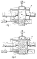
- Figs. 7-9 show schematic views of a modified embodiment of the present invention; and
- Fig. 10 is a view taken along
line 10--10 of Fig. 9. - Referring to the drawings,
baler machine 10 is designed for baling waste material such as paper, cardboard, corrugated containers, used beverage cases, municipal solid waste, etc.Machine 10 has acharging chamber 12 into which waste material is loaded. Thecharging chamber 12 is generally rectangular in horizontal section having aflat floor 14 and opposedside walls 16. Thebaler machine 10 includes ahydraulic compression cylinder 18 having acompression ram head 20 which is movable horizontally in thecharging chamber 12. - The
charging chamber 12 communicates with acompression chamber 22 through acharging passage 30.Compression chamber 22 has a fixedupper wall 24, afixed floor 26 and a movablebale decompression wall 28 located opposite and spaced fromcharging passage 30 through which waste material is compressed from thecharging chamber 12 into thecompression chamber 22 by the forward movement ofcompression ram head 20. Baledecompression wall 28 forms one wall ofcompression chamber 22. - The
compression chamber 22 further includes abale ejection cylinder 34 having anejection ram head 32.Wall 28 is movable horizontally relative to the compression chamber by a bale decompression cylinder or pair ofbale decompression cylinders 36. Thecompression chamber 22 is further provided with aexit passageway 38. Shown schematically at theexit passageway 38 is a bale strapping apparatus of suitable design indicated byreference numeral 40. - To describe the operation, reference is made to Figs. 3,4,5, and 6. After the
charging chamber 12 has been filled withwaste material 42, thecharging ram head 20 is advanced to push waste material through thecharging passage 30 and into thecompression chamber 22. - After the
chamber 22 has been filled with waste material and compressed to a suitable density, the chargingram head 20 stops in advanced position substantially flush with the corresponding side or edge of theejection ram head 32. Theejection ram head 32 is then advanced step-by-step to push the material out of thebaling chamber 22 through theexit passage 38, which retains the compressed material in its bale shape while it is tied by strappingapparatus 40. At each pause between incremental advances of theram 32, the ejected material is tied with an encircling strap or wire bystrapping mechanism 40 located just outside theexit passage 38 to prevent expansion of the compressed material to retain its bale configuration. - The strapped bale in the exit passageway serves as a cork so that a second bale can be formed in the compression chamber as described above. The rear face of the bale serves as a wall of
chamber 22 as the next bale is formed. The above describes a normal bale forming operation. - The problem to which this invention is directed is a situation where too much waste material is charged into the
baling chamber 22 for thecompression ram head 20 to push the last charge of material completely out of thecharging passage 30 into thebaling compression chamber 22. The condition is shown in Fig. 3, wherein aportion 44 of the charge in thechamber 22 protrudes back into thecharging passage 30, making it difficult, if not impossible, to eject the compressed material in thechamber 22 through theexit passage 38 by the operation of theejection ram head 32. A time-consuming manual clearing of the jam would then be necessary absent the presence of the improvement described herein. - This problem is very effectively solved as shown in Figs. 4, 5 and 6. Referring first to Fig. 4,
wall 28 is retracted by decompression cylinder(s) 36 a sufficient distance to allow thecompression ram head 20 to force the enlarged bale 46 to the position shown in Fig. 4. - In the preferred embodiment, the
wall 28 is designed to retract a variable distance and thus the effective size of the exit passageway can be adjusted (varied) as necessary to accommodate bales of various degrees of oversize. With the machine in the Fig. 4 position, the enlarged bale 46 can now be ejected from thecompression chamber 22 byejector ram head 32 as shown in Fig. 5. In this position, the discharge passageway from thecompression chamber 22 is in effect enlarged by the retracted movement ofwall 28. It will be appreciated from the above description thatdecompression wan 28 functions as one wall of thebaling compression chamber 22 and that as it is retracted, the volume of thecompression chamber 22 will be increased. Thus, as indicated, such retracted movement ofwall 28 very effectively facilitates ejection of the enlarged bale 46 from thebaling chamber 22. -
Wall 28 is then returned to its original position as shown in Figs. 3 and 6 and the bale forming operation can continue. - Figs. 7-10 show schematic views of a second embodiment of the present invention. Generally speaking, the
baler machine 48 of this embodiment is basically the same as thebaler machine 10 described above. - Baler
machine 48 is comprised of a charging chamber 50, acompression cylinder 52, acompression ram head 54, an ejection cylinder 56, anejection ram head 58, a movablebale decompression wall 60 defining acompression chamber 62. Thedecompression wall 60 is actuated horizontally by adecompression cylinder 66. Abale gate 68 is mounted at theexit passageway 69 from thecompression chamber 62. Thebale gate 68 is comprised of agate section 70 mounted for horizontal movement by apower cylinder 72 connected to thegate section 70 by aconnector bracket 74 fastened to one end of the gate. - Fig. 7 shows a first position of the baler machine with the
gate section 70 ofbale gate 68 in its partially closed position wherein theend portion 76 of thegate section 70 clamps thecork bale 78 at theexit passageway 69, thereby preventing the bale from extruding during formation of a new bale by thecompression ram head 54. - Fig. 8 shows a second position of the baler machine wherein the
bale gate 68 is moved to its fully open position and thedecompression wall 60 is retracted to permit the ejection ram head 56 to force anoversized bale 80 through theexit passageway 69. - Figs. 9 shows a third operating position of the baler mechanism with the
bale gate 68 in its fully closed position. This position is useful when the consistency of the material to be baled is such that the material in the balingchamber 62 would tend to become extruded through theexit passageway 69 during the formation of a bale inchamber 62. With the bale gate closed as shown in Fig. 9, such extrusion is prevented. The closed position of thebale gate 68 may also be useful when switching from one type of material to another type of material to be processed by the baler machine.
Claims (12)
- A baler machine comprising:(a) a charging chamber means for receiving material to be baled, said charging chamber means having a charging passage means;(b) a baling compression chamber means communicating with said charging chamber means through said charging passage means, said baling compression chamber means having an exit passageway means;(c) a compression ram means operable to force material from said charging chamber means into said baling compression chamber means through said charging passage means to thereby compress material in said baling compression chamber means;(d) ejector ram means for forcing compressed material out of said baling compression chamber through said exit passageway means;(e) a movable decompression wall means which functions as a wall of said baling compression chamber means, said movable decompression wall means located opposite and spaced from said charging passage means of said charging chamber means; and(f) power means operatively connected to said movable decompression wall means to move said movable decompression wall means from its normal operating position in a first direction to effectively increase the volume of said baling compression chamber means and further operable when moved in the opposite direction to effectively decrease the volume of said baling compression chamber means as said movable decompression means is moved back to its normal operating position by said power means.
- A baler machine according to claim 1 in which said power means is operable to move said movable decompression wall means a variable distance.
- A baler machine including a charging chamber for receiving material to be baled, a compression chamber communicating with the charging chamber through a charging passageway, a compression ram operable to force material from the charging chamber into the compression chamber, an ejector ram for forcing compressed material out of the compression chamber, the improvement comprising:(a) a movable decompression wall means which functions as a wall of the compression chamber, said movable decompression wall means located opposite and spaced from the charging passageway of the charging chamber;(b) power means operatively connected to said movable decompression wall means to move said movable decompression wall means from its normal operating position in a first direction to effectively increase the volume of said baling compression chamber means and further operable when moved in the opposite direction to effectively decrease the volume of said baling compression chamber means as said movable decompression means is moved back to its normal operating position.
- A baler machine according to claim 3 wherein said power means is operable to move said movable decompression wall means a variable distance.
- A baler machine comprising:(a) a charging chamber means for receiving material to be baled, said charging chamber means having a charging passage means;(b) a baling compression chamber means communicating with said charging chamber means through said charging passage means, said baling compression chamber means having an exit passageway means;(c) a compression ram means operable to force material from said charging chamber means into said baling compression chamber means through said charging passage means to thereby compress material in said baling compression chamber means;(d) ejector ram means for forcing compressed material out of said baling compression chamber through said exit passageway means;(e) a movable decompression wall means which functions as a wall of said baling compression chamber means, said movable decompression wall means located opposite and spaced from said charging passage means of said charging chamber means; and(f) power means operatively connected to said movable decompression wall means to move said movable decompression wall means from its normal operating position in a first direction to effectively increase the size of said exit passageway means and further operable when moved in the opposite direction to effectively decrease the size of said exit passageway means as said movable decompression wall means is moved back to its normal operating position by said power means.
- A baler machine comprising:(a) a charging chamber means for receiving material to be baled, said charging chamber means having a charging passage means;(b) a baling compression chamber means communicating with said charging chamber means through said charging passage means, said baling compression chamber means having an exit passageway means;(c) a compression ram means operable to force material from said charging chamber means into said baling compression chamber means through said charging passage means to thereby compress material in said baling compression chamber means;(d) ejector ram means for forcing compressed material out of said baling compression chamber through said exit passageway means;(e) a movable decompression wall means which functions as a wall of said baling compression chamber means, said movable decompression wall means located opposite and spaced from said charging passage means of said charging chamber means;(f) power means operatively connected to said movable decompression wall means to move said movable decompression wall means from its normal operating position in a first direction to effectively increase the volume of said baling compression chamber means and further operable when moved in the opposite direction to effectively decrease the volume of said baling compression chamber means as said movable decompression means is moved back to its normal operating position by said power means; and(g) a bale gate means mounted at said exit passageway means of said baling compression chamber means, said bale gate means operable to a partially closed position to clamp a formed bale at the exit passageway means, said bale gate means further operable to be moved to a fully open position to allow free movement of a bale from the baling chamber means through said exit passageway means, and said bale gate means further operable to be moved to a fully closed position to prevent any material in said baling compression chamber means to be extruded out through said exit passageway means.
- A baler machine comprising:(a) a charging chamber means for receiving material to be baled, said charging chamber means having a charging passage means;(b) a baling compression chamber means communicating with said charging chamber means through said charging passage means, said baling compression chamber means having an exit passageway means;(c) a compression ram means operable to force material from said charging chamber means into said baling compression chamber means through said charging passage means to thereby compress material in said baling compression chamber means;(d) ejector ram means for forcing compressed material out of said baling compression chamber through said exit passageway means;(e) a movable decompression wall means which functions as a wall of said baling compression chamber means, said movable decompression wall means located opposite and spaced from said charging passage means of said charging chamber means; and(f) power means operatively connected to said movable decompression wall means to move said movable decompression wall means from its normal operating position in a first direction to effectively increase the size of said exit passageway means and further operable when moved in the opposite direction to effectively decrease the size of said exit passageway means as said movable decompression wall means is moved back to its normal operating position by said power means; and(g) a bale gate means mounted at said exit passageway means of said baling compression chamber means, said bale gate means operable to a partially closed position to clamp a formed bale at the exit passageway means, said bale gate means further operable to be moved to a fully open position to allow free movement of a bale from the baling chamber means through said exit passageway means, and said bale gate means further operable to be moved to a fully closed position to prevent any material in said baling compression chamber means to be extruded out through said exit passageway means.
- A baler machine according to claim 7 wherein said power means is operable to move said movable decompression wall a variable distance.
- A method of forming bales comprising the steps of:(a) loading material into a charging chamber;(b) forcing the material in the charging chamber into a bale compression chamber to form a bale therein, said bale compression chamber having a side wall which is movable horizontally, said bale compression chamber having an exit passageway through which bales are ejected;(c) moving said side wall of said baling compression chamber horizontally to increase the volume of said baling compression chamber to thereby facilitate ejection of an oversized bale from said baling compression chamber; and(d) ejecting the oversized bale through the exit passageway of said baling compression chamber.
- A method of forming bales according to claim 9 wherein the movement of said side wall of said baling compression chamber is a variable distance.
- A method of forming bales comprising the steps of:(a) loading material into a charging chamber;(b) forcing the material in the charging chamber into a bale compression chamber to form a bale therein, said bale compression chamber having a side wall which is movable horizontally, said bale compression chamber having an exit passageway through which bales are ejected;(c) moving said side wall of said baling chamber horizontally to increase the size of said exit passageway to thereby facilitate ejection of an oversized bale from said baling compression chamber; and(d) ejecting the oversized bale through the exit passageway of said baling compression chamber.
- A method of forming bales comprising the steps of:(a) loading material into a charging chamber;(b) forcing the material in the charging chamber through a charging passage into a bale compression chamber to form a bale therein, said bale compression chamber having a side wall which is movable horizontally and is spaced from and positioned opposite the discharge passage, said bale compression chamber having an exit passageway through which bales are ejected;(c) moving said side wall of said baling compression chamber horizontally to increase the volume of said baling compression chamber to thereby facilitate ejection of an oversized bale from said baling compression chamber; and(d) ejecting the oversized bale through the exit passageway of said baling compression chamber.
Applications Claiming Priority (2)
| Application Number | Priority Date | Filing Date | Title |
|---|---|---|---|
| US07/774,438 US5201266A (en) | 1991-10-10 | 1991-10-10 | Baler machine and method of baling |
| US774438 | 1991-10-10 |
Publications (3)
| Publication Number | Publication Date |
|---|---|
| EP0536781A2 true EP0536781A2 (en) | 1993-04-14 |
| EP0536781A3 EP0536781A3 (en) | 1993-06-09 |
| EP0536781B1 EP0536781B1 (en) | 1995-09-06 |
Family
ID=25101231
Family Applications (1)
| Application Number | Title | Priority Date | Filing Date |
|---|---|---|---|
| EP92117311A Expired - Lifetime EP0536781B1 (en) | 1991-10-10 | 1992-10-09 | Baler machine and method of baling |
Country Status (3)
| Country | Link |
|---|---|
| US (1) | US5201266A (en) |
| EP (1) | EP0536781B1 (en) |
| DE (1) | DE69204614T2 (en) |
Cited By (4)
| Publication number | Priority date | Publication date | Assignee | Title |
|---|---|---|---|---|
| WO1996031337A1 (en) * | 1995-04-05 | 1996-10-10 | Lindemann Maschinenfabrik Gmbh | Method and apparatus for baling loose materials |
| EP1285572A1 (en) * | 2001-08-10 | 2003-02-26 | Deere & Company | Baler |
| WO2007028558A1 (en) * | 2005-09-05 | 2007-03-15 | Autefa Automation Gmbh | Method of, and apparatus for, producing pressed bales |
| WO2015113018A1 (en) * | 2014-01-27 | 2015-07-30 | Catawba Baler & Equipment, Llc | Baler for recycled materials |
Families Citing this family (13)
| Publication number | Priority date | Publication date | Assignee | Title |
|---|---|---|---|---|
| US5385089A (en) * | 1993-08-30 | 1995-01-31 | Harris Waste Management Group, Inc. | Apparatus for replacing wear components in a ram baler |
| US5463944A (en) * | 1994-10-17 | 1995-11-07 | Logemann Brothers Co. | Rotatable bale release mechanism for a baler machine and method of baling |
| IT1285433B1 (en) * | 1996-01-04 | 1998-06-08 | Lollini International Spa | PLANT FOR THE TRANSFORMATION INTO BALES OF URBAN SOLID WASTE |
| US6196124B1 (en) | 1999-07-22 | 2001-03-06 | The American Baler Company | Baling machine having two part ejector ram |
| MXPA05007723A (en) * | 2003-01-29 | 2005-09-30 | Sfk Systems As | A method and an apparatus for thawing frozen meat. |
| ES2277779B1 (en) * | 2005-12-14 | 2008-06-01 | Amadeo Farell S.A.U. | PERFECTION OF THE MACHINES FOR THE CONFECTION OF BALES OF DISGREGATED MATERIALS. |
| US7814826B2 (en) * | 2007-07-23 | 2010-10-19 | Amadeo Farell S.A.U. | Machines for making bales of disgregated material |
| US20100092356A1 (en) * | 2008-10-10 | 2010-04-15 | Estech, Llc | Solid waste compression loading and waste treatment apparatus and method |
| WO2010105270A1 (en) | 2009-03-13 | 2010-09-16 | Olaf Industries Inc. | Coil spring compactor |
| US9339982B2 (en) * | 2010-12-16 | 2016-05-17 | Sonoco Development Inc. | Waste paper rebaler |
| PL3135606T3 (en) * | 2014-03-11 | 2024-08-26 | Daicel Corporation | Packed body having filter tow bale packed in unsealed state in packing material, and method for producing same |
| US10786962B2 (en) | 2016-09-30 | 2020-09-29 | Clayton Roubideaux | Rebaling systems and methods |
| CN111730702A (en) * | 2020-06-22 | 2020-10-02 | 扬州市艾力达机电制造有限公司 | Saw machine piece packing apparatus |
Citations (5)
| Publication number | Priority date | Publication date | Assignee | Title |
|---|---|---|---|---|
| US3438320A (en) * | 1966-07-11 | 1969-04-15 | East Chicago Machine Tool Corp | Apparatus and method for compacting material |
| US3576161A (en) * | 1969-12-01 | 1971-04-27 | American Hoist & Derrick Co | Horizontal baler apparatus |
| US4658719A (en) * | 1985-11-15 | 1987-04-21 | Harris Press And Shear, Inc. | Oversize bale release mechanism for waste material baler |
| US5007337A (en) * | 1989-10-03 | 1991-04-16 | Mosley Machinery Co., Inc. | Oversize bale release mechanism for waste material baler |
| US5081922A (en) * | 1991-01-22 | 1992-01-21 | C&M Company | Device for controlling the discharge of a bale from a solid waste baling machine |
Family Cites Families (7)
| Publication number | Priority date | Publication date | Assignee | Title |
|---|---|---|---|---|
| DE494195C (en) * | 1927-06-20 | 1930-03-20 | Fried Krupp Grusonwerk Akt Ges | Baler |
| US2955529A (en) * | 1957-03-11 | 1960-10-11 | Lab Quip Engineering Corp | Packaging press |
| NL134982C (en) * | 1965-09-21 | |||
| DE2536044A1 (en) * | 1975-08-13 | 1977-03-03 | Becker & Co Kg Maschf | SCRAP PRESS |
| US4127062A (en) * | 1976-08-04 | 1978-11-28 | Isaac Egosi | Opposed box baling press |
| SU617285A1 (en) * | 1976-12-27 | 1978-07-30 | Специальное Конструкторское Бюро "Транспрогресс | Material briquetting apparatus |
| SU1143652A1 (en) * | 1983-11-17 | 1985-03-07 | Всесоюзный государственный научно-исследовательский и проектный институт асбестовой промышленности | Device for squeezing packs or bales prior to packing |
-
1991
- 1991-10-10 US US07/774,438 patent/US5201266A/en not_active Expired - Lifetime
-
1992
- 1992-10-09 DE DE69204614T patent/DE69204614T2/en not_active Expired - Fee Related
- 1992-10-09 EP EP92117311A patent/EP0536781B1/en not_active Expired - Lifetime
Patent Citations (5)
| Publication number | Priority date | Publication date | Assignee | Title |
|---|---|---|---|---|
| US3438320A (en) * | 1966-07-11 | 1969-04-15 | East Chicago Machine Tool Corp | Apparatus and method for compacting material |
| US3576161A (en) * | 1969-12-01 | 1971-04-27 | American Hoist & Derrick Co | Horizontal baler apparatus |
| US4658719A (en) * | 1985-11-15 | 1987-04-21 | Harris Press And Shear, Inc. | Oversize bale release mechanism for waste material baler |
| US5007337A (en) * | 1989-10-03 | 1991-04-16 | Mosley Machinery Co., Inc. | Oversize bale release mechanism for waste material baler |
| US5081922A (en) * | 1991-01-22 | 1992-01-21 | C&M Company | Device for controlling the discharge of a bale from a solid waste baling machine |
Cited By (7)
| Publication number | Priority date | Publication date | Assignee | Title |
|---|---|---|---|---|
| WO1996031337A1 (en) * | 1995-04-05 | 1996-10-10 | Lindemann Maschinenfabrik Gmbh | Method and apparatus for baling loose materials |
| EP1285572A1 (en) * | 2001-08-10 | 2003-02-26 | Deere & Company | Baler |
| US6715410B2 (en) | 2001-08-10 | 2004-04-06 | Deere & Company | Baling chamber having adjustable cross section |
| WO2007028558A1 (en) * | 2005-09-05 | 2007-03-15 | Autefa Automation Gmbh | Method of, and apparatus for, producing pressed bales |
| WO2015113018A1 (en) * | 2014-01-27 | 2015-07-30 | Catawba Baler & Equipment, Llc | Baler for recycled materials |
| US9248620B2 (en) | 2014-01-27 | 2016-02-02 | Catawba Baler & Equipment, Llc | Baler for recycled materials |
| US10245799B2 (en) | 2014-01-27 | 2019-04-02 | Catawba Baler & Equipment, Llc | Baler for recycled materials |
Also Published As
| Publication number | Publication date |
|---|---|
| EP0536781B1 (en) | 1995-09-06 |
| EP0536781A3 (en) | 1993-06-09 |
| US5201266A (en) | 1993-04-13 |
| DE69204614T2 (en) | 1996-02-01 |
| DE69204614D1 (en) | 1995-10-12 |
Similar Documents
| Publication | Publication Date | Title |
|---|---|---|
| US5201266A (en) | Baler machine and method of baling | |
| US5247880A (en) | Horizontal baler with movable bottom support ejector | |
| US4658719A (en) | Oversize bale release mechanism for waste material baler | |
| US5558014A (en) | Method and apparatus for baling loose materials | |
| EP2132029B1 (en) | Device and method for producing compressed bales | |
| US4121515A (en) | Baler for unshredded material | |
| US3999476A (en) | Closed chamber baler | |
| US5007337A (en) | Oversize bale release mechanism for waste material baler | |
| EP0709181B1 (en) | A rotatable bale release mechanism for a baler machine and method of baling | |
| WO2008040090A1 (en) | An apparatus and attachment for handling compressible materials | |
| US20190337253A1 (en) | Bale press | |
| US6196124B1 (en) | Baling machine having two part ejector ram | |
| US3929062A (en) | Closed chamber baler | |
| EP0080719B1 (en) | A bale press and method for compressing waste material into bales | |
| US4148253A (en) | Vertical closed chamber baler | |
| EP0932493B1 (en) | Baler | |
| GB2184979A (en) | Method and apparatus for baling | |
| DE3412307C2 (en) | Bale press for compressing materials such as paper waste or the like into bales | |
| US3942429A (en) | Method and apparatus for forming bales | |
| US4669374A (en) | Can-baling machine | |
| MXPA97008491A (en) | Apparatus and method to form pacas of materials suel | |
| JPH0665607A (en) | Method for delivering molding of powder compression molding machine and device therefor | |
| AU600808B2 (en) | Baling machine | |
| DE3625336A1 (en) | Scrap and/or refuse baling press | |
| IES960385A2 (en) | A baling press |
Legal Events
| Date | Code | Title | Description |
|---|---|---|---|
| PUAI | Public reference made under article 153(3) epc to a published international application that has entered the european phase |
Free format text: ORIGINAL CODE: 0009012 |
|
| AK | Designated contracting states |
Kind code of ref document: A2 Designated state(s): DE FR GB IT NL |
|
| PUAL | Search report despatched |
Free format text: ORIGINAL CODE: 0009013 |
|
| AK | Designated contracting states |
Kind code of ref document: A3 Designated state(s): DE FR GB IT NL |
|
| 17P | Request for examination filed |
Effective date: 19930924 |
|
| 17Q | First examination report despatched |
Effective date: 19941024 |
|
| GRAA | (expected) grant |
Free format text: ORIGINAL CODE: 0009210 |
|
| AK | Designated contracting states |
Kind code of ref document: B1 Designated state(s): DE FR GB IT NL |
|
| ITF | It: translation for a ep patent filed | ||
| REF | Corresponds to: |
Ref document number: 69204614 Country of ref document: DE Date of ref document: 19951012 |
|
| ET | Fr: translation filed | ||
| PLBE | No opposition filed within time limit |
Free format text: ORIGINAL CODE: 0009261 |
|
| STAA | Information on the status of an ep patent application or granted ep patent |
Free format text: STATUS: NO OPPOSITION FILED WITHIN TIME LIMIT |
|
| 26N | No opposition filed | ||
| PGFP | Annual fee paid to national office [announced via postgrant information from national office to epo] |
Ref country code: FR Payment date: 20011010 Year of fee payment: 10 Ref country code: GB Payment date: 20011010 Year of fee payment: 10 |
|
| PGFP | Annual fee paid to national office [announced via postgrant information from national office to epo] |
Ref country code: DE Payment date: 20011022 Year of fee payment: 10 |
|
| PGFP | Annual fee paid to national office [announced via postgrant information from national office to epo] |
Ref country code: NL Payment date: 20011031 Year of fee payment: 10 |
|
| REG | Reference to a national code |
Ref country code: GB Ref legal event code: IF02 |
|
| PG25 | Lapsed in a contracting state [announced via postgrant information from national office to epo] |
Ref country code: GB Free format text: LAPSE BECAUSE OF NON-PAYMENT OF DUE FEES Effective date: 20021009 |
|
| PG25 | Lapsed in a contracting state [announced via postgrant information from national office to epo] |
Ref country code: NL Free format text: LAPSE BECAUSE OF NON-PAYMENT OF DUE FEES Effective date: 20030501 Ref country code: DE Free format text: LAPSE BECAUSE OF NON-PAYMENT OF DUE FEES Effective date: 20030501 |
|
| GBPC | Gb: european patent ceased through non-payment of renewal fee |
Effective date: 20021009 |
|
| PG25 | Lapsed in a contracting state [announced via postgrant information from national office to epo] |
Ref country code: FR Free format text: LAPSE BECAUSE OF NON-PAYMENT OF DUE FEES Effective date: 20030630 |
|
| NLV4 | Nl: lapsed or anulled due to non-payment of the annual fee |
Effective date: 20030501 |
|
| REG | Reference to a national code |
Ref country code: FR Ref legal event code: ST |
|
| PG25 | Lapsed in a contracting state [announced via postgrant information from national office to epo] |
Ref country code: IT Free format text: LAPSE BECAUSE OF NON-PAYMENT OF DUE FEES Effective date: 20051009 |