EP0536779A1 - Kontinuierliche Zuführeinrichtung für Teile - Google Patents
Kontinuierliche Zuführeinrichtung für Teile Download PDFInfo
- Publication number
- EP0536779A1 EP0536779A1 EP92117305A EP92117305A EP0536779A1 EP 0536779 A1 EP0536779 A1 EP 0536779A1 EP 92117305 A EP92117305 A EP 92117305A EP 92117305 A EP92117305 A EP 92117305A EP 0536779 A1 EP0536779 A1 EP 0536779A1
- Authority
- EP
- European Patent Office
- Prior art keywords
- feed tube
- feed
- parts
- fasteners
- cassette
- Prior art date
- Legal status (The legal status is an assumption and is not a legal conclusion. Google has not performed a legal analysis and makes no representation as to the accuracy of the status listed.)
- Withdrawn
Links
Images


Classifications
-
- B—PERFORMING OPERATIONS; TRANSPORTING
- B23—MACHINE TOOLS; METAL-WORKING NOT OTHERWISE PROVIDED FOR
- B23P—METAL-WORKING NOT OTHERWISE PROVIDED FOR; COMBINED OPERATIONS; UNIVERSAL MACHINE TOOLS
- B23P19/00—Machines for simply fitting together or separating metal parts or objects, or metal and non-metal parts, whether or not involving some deformation; Tools or devices therefor so far as not provided for in other classes
- B23P19/04—Machines for simply fitting together or separating metal parts or objects, or metal and non-metal parts, whether or not involving some deformation; Tools or devices therefor so far as not provided for in other classes for assembling or disassembling parts
- B23P19/06—Screw or nut setting or loosening machines
- B23P19/062—Pierce nut setting machines
-
- B—PERFORMING OPERATIONS; TRANSPORTING
- B23—MACHINE TOOLS; METAL-WORKING NOT OTHERWISE PROVIDED FOR
- B23P—METAL-WORKING NOT OTHERWISE PROVIDED FOR; COMBINED OPERATIONS; UNIVERSAL MACHINE TOOLS
- B23P19/00—Machines for simply fitting together or separating metal parts or objects, or metal and non-metal parts, whether or not involving some deformation; Tools or devices therefor so far as not provided for in other classes
- B23P19/001—Article feeders for assembling machines
- B23P19/004—Feeding the articles from hoppers to machines or dispensers
-
- B—PERFORMING OPERATIONS; TRANSPORTING
- B23—MACHINE TOOLS; METAL-WORKING NOT OTHERWISE PROVIDED FOR
- B23Q—DETAILS, COMPONENTS, OR ACCESSORIES FOR MACHINE TOOLS, e.g. ARRANGEMENTS FOR COPYING OR CONTROLLING; MACHINE TOOLS IN GENERAL CHARACTERISED BY THE CONSTRUCTION OF PARTICULAR DETAILS OR COMPONENTS; COMBINATIONS OR ASSOCIATIONS OF METAL-WORKING MACHINES, NOT DIRECTED TO A PARTICULAR RESULT
- B23Q7/00—Arrangements for handling work specially combined with or arranged in, or specially adapted for use in connection with, machine tools, e.g. for conveying, loading, positioning, discharging, sorting
- B23Q7/08—Arrangements for handling work specially combined with or arranged in, or specially adapted for use in connection with, machine tools, e.g. for conveying, loading, positioning, discharging, sorting by means of slides or chutes
-
- Y—GENERAL TAGGING OF NEW TECHNOLOGICAL DEVELOPMENTS; GENERAL TAGGING OF CROSS-SECTIONAL TECHNOLOGIES SPANNING OVER SEVERAL SECTIONS OF THE IPC; TECHNICAL SUBJECTS COVERED BY FORMER USPC CROSS-REFERENCE ART COLLECTIONS [XRACs] AND DIGESTS
- Y10—TECHNICAL SUBJECTS COVERED BY FORMER USPC
- Y10T—TECHNICAL SUBJECTS COVERED BY FORMER US CLASSIFICATION
- Y10T29/00—Metal working
- Y10T29/53—Means to assemble or disassemble
- Y10T29/53039—Means to assemble or disassemble with control means energized in response to activator stimulated by condition sensor
- Y10T29/53061—Responsive to work or work-related machine element
- Y10T29/53065—Responsive to work or work-related machine element with means to fasten by deformation
- Y10T29/5307—Self-piercing work part
-
- Y—GENERAL TAGGING OF NEW TECHNOLOGICAL DEVELOPMENTS; GENERAL TAGGING OF CROSS-SECTIONAL TECHNOLOGIES SPANNING OVER SEVERAL SECTIONS OF THE IPC; TECHNICAL SUBJECTS COVERED BY FORMER USPC CROSS-REFERENCE ART COLLECTIONS [XRACs] AND DIGESTS
- Y10—TECHNICAL SUBJECTS COVERED BY FORMER USPC
- Y10T—TECHNICAL SUBJECTS COVERED BY FORMER US CLASSIFICATION
- Y10T29/00—Metal working
- Y10T29/53—Means to assemble or disassemble
- Y10T29/5343—Means to drive self-piercing work part
Definitions
- This invention concerns an apparatus to continuously supply self-attaching fasteners, such as pierce and clinch nuts, pierce form studs, and similar parts to a metal die set in a pressure application machine such as a press.
- self-attaching fasteners such as pierce and clinch nuts, pierce form studs, and similar parts
- Connecting parts such as pierce and clinch nuts and pierce form studs are used to fasten screws and bolts to parts made from steel plate or aluminum plate.
- the end faces of these connecting parts themselves may act like a punch piercing the steel or aluminum plate, and at the same time, the end face of each connecting part is sealed by the hole which it has punched out, and in this way the connecting part is fixed to the steel plate.
- the popular method of driving connecting parts such as a pierce nuts into a steel plate is to supply pierce nuts between the top and bottom platens of a metal die set in a press machine, and drive the pierce nuts into the steel plate with a drive punch as the press ram is lowered.
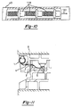
- the machine used to supply pierce nuts to the mold during this pierce nuts insertion process is a machine recorded as Japanese Patent Opening 1981-102437. This machine and the way it inserts pierce nuts are explained with reference to Figure 11 of this application.
- the machine is composed of a magazine wound in a coil shape 1 and a pipe 2 linked by a metal clamp 4. The other end of the pipe 2 is connected to the mold by a metal clamp 6.
- the pierce nuts slide smoothly inside the magazine 1 and the pipe 2, and air pressure applied from the other end of magazine 1 transports the pierce nuts through magazine 1 and pipe 2 in the direction of metal clamp 6 and supplies them to the metal mold.
- the supply of pierce nuts to the metal mold is performed continuously, synchronized with the vertical motion of the press ram K.
- This invention is intended to provide a continuous parts feeder that permits continuous transfer press operation by automatically switching from an empty magazine to a new magazine filled with parts. It is also intended to provide a continuous parts feeder that guarantees smooth parts transport when the magazines are switched over.
- This invention which achieves the aforementioned objectives is an installation apparatus having a continuous parts feeder that continuously feeds parts to the parts receiving area of a press used to insert parts, such as pierce or clinch nuts and pierce form studs to work pieces.
- the ideal operating configuration for this invention is a continuous parts feeder consisting of a parts transport tube or pipe within which parts are fed by compressed air, at least two magazines which transport parts inside the magazine to the magazine outlet sequentially by means of compressed air, a coupling device or selector valve which can switch over to selectively link the parts transport pipe entrance to the outlet of one of the magazines, a parts detector that can detect whether there are or are not parts inside the tube, and an auxiliary compressed air supply device to supply compressed air inside the parts transport tube.
- the auxiliary compressed air device When the parts stored inside the magazine that is connected to the parts transport tube have all been ejected, emptying the magazine, and as a consequence, the parts detector determines that there are no more parts, the auxiliary compressed air device is turned on to supply auxiliary compressed air to the inside of the parts supply tube at the same time as the supply of compressed air to the magazine linked to the parts supply pipe is cut off.
- the coupling device or selector valve is activated to disconnect the entrance of the parts transport pipe from the outlet of the empty magazine and connect it to the outlet of the new magazine filled with parts.
- the auxiliary compressed air supply device is shut off.
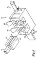
- Figure 1 is a perspective view showing the general structure of a transfer press equipped with this invention, the continuous parts feeder.
- Figure 2 is a part cross-section drawing of the installation head and the parts receiving area.
- Figure 3 is a partial cross-sectional view showing how a pierce nut is attached to a steel strip.
- Figure 4 is a perspective view of the coupling device from the side of the parts transport pipe.
- Figure 5 is a perspective view of the coupling device shown in Figure 4 from the side of a magazine.
- Figure 6 is a top plane view of the coupling device shown in Figure 4.
- Figure 7 is a side view of the coupling device shown in Figure 4.
- Figure 8 is flow chart showing the preferred operation of this invention, the continuous parts feeder.
- Figure 9 is a perspective view showing a second embodiment slide type magazine selector valve.
- Figure 10 is a partially cross-section view showing the condition of the feeder when it is feeding pierce form studs.
- Figure 11 is a schematic explanatory drawing of existing technology.
- Figure 1 is a perspective drawing showing an outline of a transfer press used to manufacture steel plate products such as automobile parts (brackets for example).
- a transfer press used to manufacture steel plate products such as automobile parts (brackets for example).
- Each metal mold or set of die platens preforms a different process including shearing, bending, or pressing to the steel plate.
- the pierce nut insertion press inserts pierce nuts into the products.
- the continuous parts feeder may be used to continuously feed pierce or clinch nuts into this nut insertion press.
- the steel plates flow as follows.
- transfer press 10 steel plates 12 are fed sequentially between the presses from right to left by a transport robot (not shown in the figure) as each of the individual presses (14 to 20) presses the steel plate to form it for a specific purpose.
- Press 14 for example shears the steel plate
- press 16 presses it
- presses 18 and 20 bend the steel plate.
- Pierce nuts are inserted into the steel plate by the pierce nut insertion press 22.
- Figure 3 shows the way in which pierce nuts may be inserted into the steel plate.
- a pierce nut 24 is inserted into the steel plate 12 and sealed by the self-attachment method.
- the installation head 28 guides the pierce nuts 24 to steel plate 12.
- the continuous parts feeder 26 continuously feeds pierce nuts 24 into the parts receiving area 30 of the head 28 in the direction indicated by the arrow 31.
- the pierce nut installation head 28 is equipped with a nose 32 that fixes the steel plate 12 that has been fed to the prescribed position from press 20 that performs the previous operation, a plunger 34 that drives pierce nuts 24 against the steel plate 12, through the nose 32, and inserts the pierce nuts into the steel plate, and a die button 36 that supports the steel plate 12 and strengthens the insertion of pierce nuts 24.
- a feature not shown in the figures is the finger attached to the head 28 that holds the pierce nuts 24 that have been transported to the parts receiving area 30.
- a proximity sensor 38 is usually installed beside the parts receiving area 30 to detect whether or not there is a pierce nut 24 in the parts receiving area.
- the press operates, and the plunger 34 comes down and inserts a pierce nut 24 in the steel plate 12 only when the proximity sensor 38 indicates that there is a pierce nut in the parts receiving area 30.
- the proximity sensor 38 does not detect the presence of a pierce nut 24, the plunger 34 does not move and the pierce nut insertion press 22 shuts down in order to prevent the press from omitting a pierce nut. As a result the entire transfer press 10 also shuts down.
- Figure 2 also shows the situation when one pierce nut 24 is inserted into each steel plate, but generally, a number of pierce nuts are inserted in every steel plate, and in these cases it is necessary to attach multiple heads equal in number to the number of pierce nuts that are inserted.
- FIG. 1 is a slightly expanded example of this continuous parts feeder attached to pierce nut insertion press 22.
- the continuous parts feeder 26 consists of parts transport or feed tube 40 connected to the head 28 so that it can supply pierce nuts 24 to head 28, two magazines 42 and 44 that replenish the stock of pierce nuts 24 in the parts transport or feed tube 40, the coupling device or selector valve 46 that is able to switch in order to selectively link the parts transport or feed tube 40 to either magazine 42 or magazine 44, and the automatic control device 48 that automatically controls the action of the selector valve 46.
- the pierce nut exit 50 which can be linked to the parts receiving area 30, is on one end of the parts transport tube 40, while the entrance or inlet 52, where pierce nuts are inserted, is on the other end of the parts feed tube.
- the detection position 54 which is preferably near the entrance 52 of the parts feed tube 40, is the location of the parts detector device such as a magnetic sensor 56 that detects the presence or absence of a pierce nut inside the feed tube.
- the coupler 58 on the auxiliary compressed air supply device 57 that supplies compressed air inside the feed tube is installed between the entrance 52 and the magnetic sensor 56.
- the auxiliary compressed air supply device 57 is linked to a solenoid valve (not shown) and to a vinyl tube 60 that brings compressed air from the factory's compressed air supply system.
- Exits 62 and 64 at the ends of the transfer tubes of the two magazines 42 and 44 respectively, are connected to the coupling device 46, and the pierce nuts inside the magazines are fed to the parts feed tube 40 by selectively linking either outlet 62 or 64 to the entrance 52 of the parts feed tube 40.
- This transport operation is performed by compressed air from either compressed air outlets 66 or 68 in the opposite ends of the magazines.
- the automatic control device 48 controls the auxiliary compressed air supply device 57 that supplies compressed air inside the parts transport pipe, and the compressed air supply device (not shown in the diagrams) that provides compressed air to the magazine compressed air inlets 66 and 68, and the coupling device 46.
- FIGs 4 to 7 illustrate one embodiment of the parts transfer valve 46.
- Figure 4 is a perspective drawing of the coupling device or transfer valve from the side of the parts transfer tube entrance;
- Figure 5 is a perspective drawing of the coupling device from the side of the magazine outlet,
- Figure 6 is a plane view of the coupling device, and
- Figure 7 is lateral view of the coupling device.
- This coupling device 46 consists of stationary housing 70 to which the magazines can be freely attached or detached, a slide valve plate 72 that operates in concert with the stationary housing 70, and an air cylinder 74 that moves the slide valve disk in the direction indicated by the arrow 73.
- the housing 70 and the slide valve plate 72 form the slide type magazine transfer valve 76.
- an attachment block 80 is installed at the magazine outlet 62 to connect the magazine 42 to the magazine outlet connecting opening 78 of housing 70.
- This attachment block 80 is penetrated by magazine 42.
- magazine outlet 62 is connected to coupling device 46. So that the transfer tube of coupled magazine 42 will not easily slip out of place, a protrusion 84 installed on the magazine outlet connecting opening 78 is structured to fit inside the groove 86 on the attachment block 80. This coupling is performed by the magazine mounting and dismounting lever 82.
- the slide valve plate 72 can be moved in the direction indicated by the arrow 73 by the action of an actuator, such as the air cylinder 74, so that either magazine outlet 62 or 64 of the two connected magazines can be selectively linked to the entrance 52 of the parts transport tube.
- the slide valve plate 72 may be welded to the attachment block 88 that is itself connected to the entrance 52 of the parts transport tube.
- An opening 90 that permits the passage of pierce nuts is cut in the slide valve plate 72 at the part that is attached to the attachment block 88, and parts transfer tube 40 penetrates attachment block 88 and opening 90.
- the slide valve plate 72 is moved in the direction indicated by the arrow 73 by the air cylinder 74, and where the attachment block 89 attached to the side valve plate 72 adheres to the stationary material 70, the transfer tube of magazine outlet 62, and parts pipe transport entrance 52 are connected so that pierce nuts can pass through them. At this time, magazine outlet 64 is sealed by the slide valve plate 72.
- the connection is switched by moving parts transport tube 40 from the position shown by the solid line 92, to the position shown by the 2-dot & 1-dash line 94 ( Figure 6 shows it when it is switched from the transfer tube of magazine 42 to magazine 44.)
- the parts feed tube 40 is preferably formed from flexible plastic so that it can bend freely with the action of the slide valve plate 72.
- a coupler 96 is installed on the attachment block 88 at the entrance 52 of the feed tube. Auxiliary compressed air is passed through this coupler to the inside of parts transport tube 40. As already mentioned, a magnetic sensor 56 is installed. So that there will be sufficient pierce nuts left in the parts transport tube 40 when magazine switch over occurs, the coupler 96 is preferably as close as possible to the entrance 52 of the parts feed tube 40. For the same reason, the magnetic sensor 56 should be close to the entrance of the parts transport tube.
- the supply of compressed air from magazine compressed air inlets 66 and 68 is controlled by the automatic control device 48 so that compressed air is supplied only to the magazine connected to the parts transport or feed tube 40, but compressed air may also be supplied continually to the two magazines.
- a proximity sensor 98 may also be installed to confirm that the slide valve plate 72 is moving correctly.
- the example consists of two magazines connected to the feeder, but it can be designed to use more than two magazines at the same time by providing more than two linked magazine outlet openings. It is also possible to use an oval shaped slide type magazine selector valve, and construct the device so that it switches magazines by rotating the entrance of the parts transport pipe. If the device is structured in this manner, it is possible to attach many magazines to the stationary material which provides the operation with additional leeway.
- a buzzer or emergency light informs the operator that the magazines have automatically switched, the operator can remove the empty magazine from the coupling device and attach another one that has already been filled with parts to the coupling device so that he will not have to check on the feeder until the next time he hears the buzzer.
- the continuous parts feeder 26 is illustrated by the flow chart in Figure 8 and by Figures 2 and 4.
- the proximity sensor 38 determines whether or not a pierce nut is supplied to the head 28 (STI).
- the pierce nut insertion press 22 stops in emergency stop mode (ST2).
- ST3 When a pierce nut has been supplied to the head, pierce nut insertion occurs (ST3).
- the magnetic sensor 56 determines whether or not there is a pierce nut at detection position 54 (ST4).
- the automatic control, device 48 activates the auxiliary compressed air supply device 46, end compressed air is supplied to the inside of parts supply or feed tube 40 from the coupler 96 (ST5).
- the supply of compressed air to magazine 42 that is connected to the parts supply tube 40 is cut off (ST6).
- the action of air cylinder 74 disconnects the parts supply tube 40 from the empty magazine 42, and connects it to the magazine 44 that is filled with pierce nuts (ST7).
- compressed air is supplied to the inside of magazine 44 from the magazine compressed air inlet 68 (ST8).
- the supply of auxiliary compressed air is cut off (ST9).
- a buzzer or emergency light (not shown in the diagrams) is turned on to let the operator know that magazine 42 is empty (ST10).
- the compressed air supplied from coupler 96 is used as an auxiliary supply, but it is also acceptable for coupler 96 to supply compressed air all the time.
- the coupling device is switched over so that the entrance to the parts transport pipe 40 is disconnected from the outlet of an empty magazine and coupled to the outlet of a new magazine which is filled with parts at the same time as the compressed air supply from the compressed air outlet in the empty magazine is stopped and the compressed air outlet in the new magazine that is filled with parts begins to supply compressed air. It is possible to use a limit switch and a sensor that operate In conjunction with the action of the attachment block 38 to switch the compressed air supply between the compressed air out lets of the magazines.
- Figure 9 illustrates another embodiment of the slide type magazine selector valve. This figure, however, is not the same as the that of the slide type magazine selector valve shown in Figure 4.
- the entrance to the parts transport pipe is connected to the slide valve plate, so that it moves with the slide valve plate, but with the slide type magazine selector valve 100 shown in Figure 9, transfer tubes of magazines 41 and 44 are connected to the slide valve disk 102, and it is designed so that they are moved by the air cylinder in the direction indicated by the arrow 104 in concert with the slide valve plate 102.
- the stationary housing 106 is, therefore, linked to the parts transport tube 40.
- Attachment blocks 108 and 110 are installed at the outlets of magazines 42 and 44 respectively, and they can be attached to or detached from the slide valve plate 102. These attachment blocks 108 and 110, penetrate the slide valve plate 102, and magazines 42 and 44 penetrate these attachment blocks 108 and 110. The outlets of magazines 42 and 44 coincide with openings 114 and 116 respectively that are cut in the slide valve plate.
- Attachment block 112 is installed at the entrance or inlet to the parts transport or feed tube 40, and the parts feed tube 40 penetrates this attachment block 112.
- This structure means that the entrance to the feed tube 40 is connected to the outlet of either magazine 42 or magazine 44.
- the outlet of the magazine not in use is closed by the slide valve plate, but with this slide type magazine selector valve 100, the housing 106 closes the outlet of the valve that is not in use.
- Figure 10 shows how pierce form studs are transported.
- the pierce form studs 118 are lined up in the feed tube 40 (or the transfer tubes of magazines 42 and 44) so they are fed in the pierce form stud axial direction and transported in the direction indicated by arrow 120 by compressed air.
- the continuous parts feeder presented in this actual example When the continuous parts feeder presented in this actual example is installed on a parts insertion press such as a pierce nut insertion press, it can supply parts continuously because whenever there are no more pierce nuts in a magazine during machine operation, the feeder automatically selects a new magazine that is filled with pierce nuts. Because a buzzer or emergency light then informs the operator that he must replace a magazine, he need not periodically check on the magazines as in the past, and can carry on with other work without any need to worry that the feeder has run out of pierce nuts or other parts. Also, because magazine selection is not performed by the operator as in the past, but mechanically at high speed, there should be no more human errors.
- this invention is designed so that when one of at least two magazines runs out of parts, the parts feed tube automatically switches from the empty magazine to a new magazine that is filled with parts, so that as long as parts are supplied by the new magazine, it is possible to continuously operate the parts insertion press. Also when magazine switch-over occurs, compressed air is supplied to the inside of the parts feed tube by the auxiliary compressed air supply device so that smooth parts feeding is performed inside the parts feed tube.
Landscapes
- Engineering & Computer Science (AREA)
- Mechanical Engineering (AREA)
- Automatic Assembly (AREA)
- Branching, Merging, And Special Transfer Between Conveyors (AREA)
Applications Claiming Priority (2)
| Application Number | Priority Date | Filing Date | Title |
|---|---|---|---|
| JP3292182A JP2950662B2 (ja) | 1991-10-11 | 1991-10-11 | 部品連続供給装置 |
| JP292182/91 | 1991-10-11 |
Publications (1)
| Publication Number | Publication Date |
|---|---|
| EP0536779A1 true EP0536779A1 (de) | 1993-04-14 |
Family
ID=17778627
Family Applications (1)
| Application Number | Title | Priority Date | Filing Date |
|---|---|---|---|
| EP92117305A Withdrawn EP0536779A1 (de) | 1991-10-11 | 1992-10-09 | Kontinuierliche Zuführeinrichtung für Teile |
Country Status (4)
| Country | Link |
|---|---|
| US (1) | US5299351A (de) |
| EP (1) | EP0536779A1 (de) |
| JP (1) | JP2950662B2 (de) |
| CA (1) | CA2080190C (de) |
Cited By (9)
| Publication number | Priority date | Publication date | Assignee | Title |
|---|---|---|---|---|
| EP0703037A1 (de) * | 1994-09-26 | 1996-03-27 | Aoyama Seisakusho Co., Ltd. | Gerät zum kontinuierlichen Fördern und Setzen von vernichtbaren Muttern |
| ES2127053A1 (es) * | 1995-05-05 | 1999-04-01 | Casas Francisco J Codina | Procedimiento para la alimentacion de tuercas a una maquina de soldadura y aparato para su ejecucion. |
| EP0995537A2 (de) * | 1998-10-23 | 2000-04-26 | Northrop Grumman Corporation | System und Verfahren zum Zuführen von Befestigungselementen mit Beibehaltung der Orientierung |
| EP1080826A1 (de) * | 1999-09-06 | 2001-03-07 | Yugenkaisha Shinjo Seisakusho | Vorrichtung zur automatischen Befestigung von selbststanzenden Befestigungselementen auf einem Artikel |
| FR2842181A1 (fr) * | 2002-07-12 | 2004-01-16 | F2 C2 System | Dispositif de stockage et de distribution de pieces notamment de rivets |
| USRE39624E1 (en) * | 1999-12-24 | 2007-05-15 | Bas Components Limited | Feed head |
| WO2019110993A1 (en) * | 2017-12-05 | 2019-06-13 | Henrob Limited | Fastener handling devices for fastener setting machines, and related methods |
| CN111618577A (zh) * | 2020-06-04 | 2020-09-04 | 安徽机电职业技术学院 | 一种指尖陀螺的自动装配设备 |
| US11167340B2 (en) | 2017-12-05 | 2021-11-09 | Atlas Copco Ias Uk Limited | Nose arrangements for fastener setting machines, and related methods |
Families Citing this family (21)
| Publication number | Priority date | Publication date | Assignee | Title |
|---|---|---|---|---|
| US5454775A (en) * | 1994-09-13 | 1995-10-03 | Applied Robotics, Inc. | Automated exchangeable parts feeding system |
| US5666838A (en) * | 1995-06-05 | 1997-09-16 | Efco, Incorporated | Forging press for use with automated multi-station transport system |
| US5642650A (en) * | 1995-11-07 | 1997-07-01 | Tri-Vision International Corporation | Stock depletion sensor |
| US6164489A (en) * | 1998-03-25 | 2000-12-26 | Fabristeel Products, Inc. | Carousel feed |
| GB9816796D0 (en) | 1998-08-03 | 1998-09-30 | Henrob Ltd | Improvements in or relating to fastening machines |
| US6751572B1 (en) * | 2000-08-31 | 2004-06-15 | Rockwell Automation Technologies, Inc. | Auto-correcting part measurement system |
| US6567761B1 (en) * | 2000-08-31 | 2003-05-20 | Rockwell Automation Technologies, Inc. | In-die part measurement system |
| US6986450B2 (en) * | 2003-04-30 | 2006-01-17 | Henrob Limited | Fastener insertion apparatus |
| US7975522B2 (en) * | 2005-05-05 | 2011-07-12 | Whitesell International Corporation | Fastener manufacturing assembly and method |
| DE102005041534A1 (de) | 2005-08-31 | 2007-03-01 | Newfrey Llc, Newark | Verfahren und Vorrichtung zum Zuführen von Verbindungselementen zu einem Verarbeitungsgerät |
| US7401695B2 (en) | 2006-06-07 | 2008-07-22 | The Gillette Company | Component control device, systems, and methods |
| US8881364B2 (en) * | 2010-12-03 | 2014-11-11 | Btm Corporation | Pierce nut insertion tool |
| JP5677614B1 (ja) * | 2014-07-30 | 2015-02-25 | 株式会社ムロコーポレーション | ワッシャー積層供給機構付き連続ビス締め付け機 |
| US10160038B1 (en) * | 2014-08-29 | 2018-12-25 | Logan Clutch Corporation | Multi-spindle machine control system |
| DE102016210799A1 (de) | 2016-06-16 | 2017-12-21 | Leoni Kabel Gmbh | Kupplungsvorrichtung zum Verbinden langgestreckter Hohlkörper in einem Montagesystem |
| IT201700015948A1 (it) * | 2017-02-14 | 2018-08-14 | A M F S P A | Dispositivo e metodo per l’applicazione di inserti su supporti laminari e kit per uso in tale dispositivo |
| CN107472829A (zh) * | 2017-09-05 | 2017-12-15 | 科成精密模塑科技无锡有限公司 | 自动放螺母装置 |
| CN108176966B (zh) * | 2018-01-19 | 2023-09-19 | 天津力佑智能装备有限公司 | 套管端帽组装机 |
| CN110202344A (zh) * | 2019-06-10 | 2019-09-06 | 玉柴联合动力股份有限公司 | 一种气缸盖座圈压装用的及时供料装置 |
| CN110355561A (zh) * | 2019-08-02 | 2019-10-22 | 沈阳金杯延锋汽车内饰系统有限公司 | 一种可以实现螺钉自动定向装配的汽车门板装配工装 |
| EP3907017B1 (de) * | 2020-05-06 | 2023-02-22 | Newfrey LLC | Befestigungsvorrichtung, befestigungssystem und verfahren zum zuführen von befestigungselementen |
Citations (5)
| Publication number | Priority date | Publication date | Assignee | Title |
|---|---|---|---|---|
| US3568229A (en) * | 1969-04-07 | 1971-03-09 | Moorfeed Corp | Screw-washer assembly apparatus |
| GB2067149A (en) * | 1980-01-11 | 1981-07-22 | Toyota Motor Co Ltd | Supply magazines for component parts |
| EP0197909A1 (de) * | 1985-04-09 | 1986-10-15 | Asea Ab | Einrichtung und Verfahren zum automatischen Montieren von Muttern |
| FR2613336A1 (fr) * | 1987-03-31 | 1988-10-07 | Merlin Gerin | Poste d'assemblage a systeme de distribution a haute cadence |
| US4949833A (en) * | 1987-08-18 | 1990-08-21 | Mazda Motor Corporation | Apparatus for successive supply of parts |
Family Cites Families (11)
| Publication number | Priority date | Publication date | Assignee | Title |
|---|---|---|---|---|
| US3140010A (en) * | 1961-12-05 | 1964-07-07 | Multifastener Corp | Method of and apparatus for dispensing fasteners |
| US3334724A (en) * | 1966-03-16 | 1967-08-08 | Multifastener Corp | Variable strength magnetic nut feeder |
| US3845860A (en) * | 1971-04-01 | 1974-11-05 | Multifastener Corp | Fastener strip |
| US3759418A (en) * | 1971-06-11 | 1973-09-18 | Multifastener Corp | Part orienting device |
| US3823803A (en) * | 1972-12-26 | 1974-07-16 | Multifastener Corp | Nut transfer and orienting device |
| US3858299A (en) * | 1973-08-27 | 1975-01-07 | Multifastener Corp | Nut coil de-reeler |
| US3971116A (en) * | 1975-05-05 | 1976-07-27 | Multifastener Corporation | Fastener installation head |
| US4765057A (en) * | 1980-02-02 | 1988-08-23 | Multifastener Corporation | Self-attaching fastener, panel assembly and installation apparatus |
| US4442584A (en) * | 1980-02-06 | 1984-04-17 | Multifastener Corporation | Nut installation apparatus, method and controls |
| US4532664A (en) * | 1980-05-20 | 1985-08-06 | Multifastener Corporation | Fastener orienting, tapping and collection system |
| US4941795A (en) * | 1988-11-21 | 1990-07-17 | At&T Bell Laboratories | Component insertion machine apparatus |
-
1991
- 1991-10-11 JP JP3292182A patent/JP2950662B2/ja not_active Expired - Lifetime
-
1992
- 1992-10-08 CA CA002080190A patent/CA2080190C/en not_active Expired - Fee Related
- 1992-10-09 US US07/958,984 patent/US5299351A/en not_active Expired - Lifetime
- 1992-10-09 EP EP92117305A patent/EP0536779A1/de not_active Withdrawn
Patent Citations (5)
| Publication number | Priority date | Publication date | Assignee | Title |
|---|---|---|---|---|
| US3568229A (en) * | 1969-04-07 | 1971-03-09 | Moorfeed Corp | Screw-washer assembly apparatus |
| GB2067149A (en) * | 1980-01-11 | 1981-07-22 | Toyota Motor Co Ltd | Supply magazines for component parts |
| EP0197909A1 (de) * | 1985-04-09 | 1986-10-15 | Asea Ab | Einrichtung und Verfahren zum automatischen Montieren von Muttern |
| FR2613336A1 (fr) * | 1987-03-31 | 1988-10-07 | Merlin Gerin | Poste d'assemblage a systeme de distribution a haute cadence |
| US4949833A (en) * | 1987-08-18 | 1990-08-21 | Mazda Motor Corporation | Apparatus for successive supply of parts |
Non-Patent Citations (2)
| Title |
|---|
| PATENT ABSTRACTS OF JAPAN vol. 009, no. 242 (M-417)28 September 1985 & JP-A-60 094 234 ( MATSUSHITA ) 27 May 1985 * |
| PATENT ABSTRACTS OF JAPAN vol. 011, no. 057 (M-564)21 February 1987 & JP-A-61 219 541 ( MATSUSHITA ) 29 September 1986 * |
Cited By (15)
| Publication number | Priority date | Publication date | Assignee | Title |
|---|---|---|---|---|
| EP0703037A1 (de) * | 1994-09-26 | 1996-03-27 | Aoyama Seisakusho Co., Ltd. | Gerät zum kontinuierlichen Fördern und Setzen von vernichtbaren Muttern |
| ES2127053A1 (es) * | 1995-05-05 | 1999-04-01 | Casas Francisco J Codina | Procedimiento para la alimentacion de tuercas a una maquina de soldadura y aparato para su ejecucion. |
| EP0995537A2 (de) * | 1998-10-23 | 2000-04-26 | Northrop Grumman Corporation | System und Verfahren zum Zuführen von Befestigungselementen mit Beibehaltung der Orientierung |
| EP0995537A3 (de) * | 1998-10-23 | 2000-07-26 | Northrop Grumman Corporation | System und Verfahren zum Zuführen von Befestigungselementen mit Beibehaltung der Orientierung |
| EP1080826A1 (de) * | 1999-09-06 | 2001-03-07 | Yugenkaisha Shinjo Seisakusho | Vorrichtung zur automatischen Befestigung von selbststanzenden Befestigungselementen auf einem Artikel |
| USRE39624E1 (en) * | 1999-12-24 | 2007-05-15 | Bas Components Limited | Feed head |
| WO2004007142A1 (fr) * | 2002-07-12 | 2004-01-22 | F2 C2 System | Dispositif de stockage et de distribution de pieces notamment de rivets |
| FR2842181A1 (fr) * | 2002-07-12 | 2004-01-16 | F2 C2 System | Dispositif de stockage et de distribution de pieces notamment de rivets |
| US7882981B2 (en) | 2002-07-12 | 2011-02-08 | F2 C2 System | Device for storing and dispensing parts in particular rivets |
| WO2019110993A1 (en) * | 2017-12-05 | 2019-06-13 | Henrob Limited | Fastener handling devices for fastener setting machines, and related methods |
| US11167340B2 (en) | 2017-12-05 | 2021-11-09 | Atlas Copco Ias Uk Limited | Nose arrangements for fastener setting machines, and related methods |
| US11241729B2 (en) | 2017-12-05 | 2022-02-08 | Atlas Copco Ias Uk Limited | Fastener handling devices for fastener setting machines, and related methods |
| US11673183B2 (en) | 2017-12-05 | 2023-06-13 | Atlas Copco Ias Uk Limited | Fastener handling devices for fastener setting machines, and related methods |
| US11919066B2 (en) | 2017-12-05 | 2024-03-05 | Atlas Copco Ias Uk Limited | Nose arrangements for fastener setting machines, and related methods |
| CN111618577A (zh) * | 2020-06-04 | 2020-09-04 | 安徽机电职业技术学院 | 一种指尖陀螺的自动装配设备 |
Also Published As
| Publication number | Publication date |
|---|---|
| US5299351A (en) | 1994-04-05 |
| CA2080190A1 (en) | 1993-04-12 |
| CA2080190C (en) | 1995-07-04 |
| JP2950662B2 (ja) | 1999-09-20 |
| JPH05104339A (ja) | 1993-04-27 |
Similar Documents
| Publication | Publication Date | Title |
|---|---|---|
| US5299351A (en) | Continuous parts feeder | |
| US6098442A (en) | Fastening device and method and apparatus for supplying fastening elements thereto | |
| US4754643A (en) | Method and apparatus for automatically installing mandrel rivets | |
| US7748097B1 (en) | Fastener insertion apparatus | |
| EP2308613B1 (de) | Verfahren und Vorrichtung zur Zuführung von Befestigungselementen | |
| US5653368A (en) | Fastener installation apparatus | |
| EP0995518A2 (de) | Steuerung des Arbeitszyklus eines Nietwerkzeuges | |
| EP1010483A2 (de) | Modulares tragbares Nietwerkzeug | |
| EP0491193A2 (de) | Automatische Nietzufuhrvorrichtung | |
| US8881364B2 (en) | Pierce nut insertion tool | |
| EP1606076B1 (de) | Selbstdiagnostizierende vorrichtung zur befestigung von selbststanzenden muttern | |
| US20100044409A1 (en) | Method for Determining and Setting Material Release Mechanism Timing for a Material Feed Mechanism | |
| US20170355013A1 (en) | Continuous Fastener Feeding Apparatus and Method | |
| US6079604A (en) | Rivet tool escapement mechanism | |
| US6018863A (en) | Fastener installation head having a pivoting fastener drive assembly | |
| JPH08509172A (ja) | ファスナー部圧入用圧入装置 | |
| CA1153188A (en) | Nut installation apparatus and method | |
| EP0995519A2 (de) | Verstellbare Vorrichtung zum Zufuhren von Nieten an einem Nietwerkzeug | |
| EP0130076B1 (de) | Nietmaschinen | |
| CZ317796A3 (en) | Equipment intended for use in a press for supply connecting elements and their fastening in workpieces by pressing | |
| EP0703037B1 (de) | Gerät zum kontinuierlichen Fördern und Setzen von vernichtbaren Muttern | |
| GB2281877A (en) | Workpiece finishing and presentation machine | |
| US4442584A (en) | Nut installation apparatus, method and controls | |
| EP1349723B1 (de) | Verfahren und vorrichtung zur bestimmung und einstellung des materialfreigabemechanismus-zeitpunkts für einen materialzuführmechanismus | |
| US4998659A (en) | Self-attaching fastener installation head |
Legal Events
| Date | Code | Title | Description |
|---|---|---|---|
| PUAI | Public reference made under article 153(3) epc to a published international application that has entered the european phase |
Free format text: ORIGINAL CODE: 0009012 |
|
| AK | Designated contracting states |
Kind code of ref document: A1 Designated state(s): DE ES FR GB IT SE |
|
| 17P | Request for examination filed |
Effective date: 19931014 |
|
| 17Q | First examination report despatched |
Effective date: 19950809 |
|
| STAA | Information on the status of an ep patent application or granted ep patent |
Free format text: STATUS: THE APPLICATION IS DEEMED TO BE WITHDRAWN |
|
| 18D | Application deemed to be withdrawn |
Effective date: 19960220 |