EP0536637B1 - Piezo-electric device type actuator - Google Patents
Piezo-electric device type actuator Download PDFInfo
- Publication number
- EP0536637B1 EP0536637B1 EP92116792A EP92116792A EP0536637B1 EP 0536637 B1 EP0536637 B1 EP 0536637B1 EP 92116792 A EP92116792 A EP 92116792A EP 92116792 A EP92116792 A EP 92116792A EP 0536637 B1 EP0536637 B1 EP 0536637B1
- Authority
- EP
- European Patent Office
- Prior art keywords
- electric device
- piezo
- laminated
- laminated piezo
- base member
- Prior art date
- Legal status (The legal status is an assumption and is not a legal conclusion. Google has not performed a legal analysis and makes no representation as to the accuracy of the status listed.)
- Expired - Lifetime
Links
- 239000000919 ceramic Substances 0.000 claims description 9
- 238000006073 displacement reaction Methods 0.000 description 8
- 238000003466 welding Methods 0.000 description 7
- 239000000853 adhesive Substances 0.000 description 4
- 230000001070 adhesive effect Effects 0.000 description 4
- 238000010276 construction Methods 0.000 description 2
- WABPQHHGFIMREM-UHFFFAOYSA-N lead(0) Chemical compound [Pb] WABPQHHGFIMREM-UHFFFAOYSA-N 0.000 description 2
- 239000002184 metal Substances 0.000 description 2
- 230000035939 shock Effects 0.000 description 2
- 230000001133 acceleration Effects 0.000 description 1
- 238000005452 bending Methods 0.000 description 1
- 230000015572 biosynthetic process Effects 0.000 description 1
- 230000006835 compression Effects 0.000 description 1
- 238000007906 compression Methods 0.000 description 1
- 238000009413 insulation Methods 0.000 description 1
- 238000010030 laminating Methods 0.000 description 1
- 230000002093 peripheral effect Effects 0.000 description 1
- 238000011084 recovery Methods 0.000 description 1
- 238000005245 sintering Methods 0.000 description 1
- 230000000087 stabilizing effect Effects 0.000 description 1
Images
Classifications
-
- B—PERFORMING OPERATIONS; TRANSPORTING
- B41—PRINTING; LINING MACHINES; TYPEWRITERS; STAMPS
- B41J—TYPEWRITERS; SELECTIVE PRINTING MECHANISMS, i.e. MECHANISMS PRINTING OTHERWISE THAN FROM A FORME; CORRECTION OF TYPOGRAPHICAL ERRORS
- B41J2/00—Typewriters or selective printing mechanisms characterised by the printing or marking process for which they are designed
- B41J2/22—Typewriters or selective printing mechanisms characterised by the printing or marking process for which they are designed characterised by selective application of impact or pressure on a printing material or impression-transfer material
- B41J2/23—Typewriters or selective printing mechanisms characterised by the printing or marking process for which they are designed characterised by selective application of impact or pressure on a printing material or impression-transfer material using print wires
- B41J2/27—Actuators for print wires
- B41J2/295—Actuators for print wires using piezoelectric elements
-
- H—ELECTRICITY
- H10—SEMICONDUCTOR DEVICES; ELECTRIC SOLID-STATE DEVICES NOT OTHERWISE PROVIDED FOR
- H10N—ELECTRIC SOLID-STATE DEVICES NOT OTHERWISE PROVIDED FOR
- H10N30/00—Piezoelectric or electrostrictive devices
- H10N30/50—Piezoelectric or electrostrictive devices having a stacked or multilayer structure
-
- H—ELECTRICITY
- H10—SEMICONDUCTOR DEVICES; ELECTRIC SOLID-STATE DEVICES NOT OTHERWISE PROVIDED FOR
- H10N—ELECTRIC SOLID-STATE DEVICES NOT OTHERWISE PROVIDED FOR
- H10N30/00—Piezoelectric or electrostrictive devices
- H10N30/80—Constructional details
- H10N30/88—Mounts; Supports; Enclosures; Casings
- H10N30/886—Mechanical prestressing means, e.g. springs
-
- H—ELECTRICITY
- H02—GENERATION; CONVERSION OR DISTRIBUTION OF ELECTRIC POWER
- H02N—ELECTRIC MACHINES NOT OTHERWISE PROVIDED FOR
- H02N2/00—Electric machines in general using piezoelectric effect, electrostriction or magnetostriction
- H02N2/02—Electric machines in general using piezoelectric effect, electrostriction or magnetostriction producing linear motion, e.g. actuators; Linear positioners ; Linear motors
- H02N2/04—Constructional details
- H02N2/043—Mechanical transmission means, e.g. for stroke amplification
Definitions
- This invention relates to a piezo-electric device type actuator suitable for use on a wire dot printer or the like.
- laminated piezo-electric devices are increasingly resorted to for driving printing wires on a printing head.
- the laminated piezo-electric devices usually contain a plural number of internal electrodes and a couple of external electrodes, which are connected to the internal electrodes, and are required to have high reliability since they are driven under high voltage and severe operating conditions.
- the printing element 1 is constituted by a displacement magnifying mechanism 2, an actuator 3, a base member 4 linking the displacement magnifying mechanism 2 and the actuator 3, and a movable block 5.
- the displacement magnifying mechanism 2 is constituted by an armature 6, and a pair of leaf springs 7 and 8 which are disposed in parallel relation with each other to support one end of the armature 6.
- the leaf spring 7 is fixedly secured to the base member 4, while the other leaf spring 8 is fixedly secured to the movable block 5.
- a printing wire 9 is securely fixed to the other end of the armature 6.
- the actuator 3 is constituted by a laminated piezo-electric device 10, blocks 11 and 12 which are located at the opposite ends of the laminated piezo-electric device 10 in such a manner as to sandwich the latter, and resilient plates 13a and 13b which are extended along the opposite sides of the laminated piezo-electric device 10 and welded to the latter by laser welding at the positions of points P while applying a predetermined compressive force to the laminated piezo-electric device 10.
- the blocks 11 and 12 are fixedly bonded to the movable block 5 and base member 4, respectively, by the use of an adhesive.
- the block 11 is linked to the base member 4 through a leaf spring 15 for the purpose of stabilizing the operation of the laminated piezo-electric device 10.
- the laminated piezo-electric device 10 is constituted by a plural number of laminated piezo-electric ceramics layers, a plural number of internal electrodes which are sandwiched between the respective piezo-electric ceramics layers, a couple of external electrodes which are alternately connected to every other internal electrode, and lead wires 14a and 14b which are connected to the external electrodes 13a and 13b, respectively.
- the laminated type piezo-electric device 10 Upon applying a drive voltage to the lead wires 14a and 14b, the laminated type piezo-electric device 10 is deformed to stretch by ten and several micrometers. As a result, the movable block 5 is pushed in the leftward direction in Fig. 1, and the armature 6 is turned about its lower end portion by bi-metal action of the leaf springs 7 and 8 to magnify the displacement of the movable block 5, thereby driving the printing wire 9 to protrude forward by several hundred micrometers. As a result, the wire 9 is hit against the platen, through an ink ribbon and a printing paper sheet which are not shown, to print a dot on the paper.
- a piezo-electric device type actuator constituted by: a laminated piezo-electric device including a plural number of laminated piezo-electric ceramics layers, a plural number of internal electrodes sandwiched between the respective piezo-electric ceramics layers, a first external electrode connected to alternate ones of the internal electrodes, and a second external electrode connected to the other alternate ones of the internal electrodes, the laminated piezo-electric device having first and second side surfaces on the opposite lateral sides thereof; a stationary base member; a pair of resilient plates extended along the first and second side surfaces of the laminated piezo-electric device, respectively, and each welded at one end to the base member; and a movable block welded to the other end of each of the resilient plates while applying a predetermined compressive force to the laminated piezo-electric device.
- the paired resilient members are fixedly welded to the movable block and base member to secure higher strength than the conventional fixation by an adhesive.
- the piezo-electric device type actuator can ensure stabilized performance quality in printing operation.
- a printing head incorporating a piezo-electric device type actuator according the present invention.
- the printing head is constituted by a plural number of printing elements 20 which are mounted along the inner peripheral surface of a base member 26 of substantially cylindrical shape.
- Each printing element 20 includes a displacement magnifying mechanism 22, a piezo-electric device type actuator 24, a base member 26 to which one end of the piezo-electric device type actuator 24 is fixedly connected, and a movable block 28 to which the other end of the actuator 24 is fixedly connected.
- the displacement magnifying mechanism 22 includes an armature 30, and a pair of parallelly disposed leaf springs 32 and 34 which are securely fixed to one end of the armature 30.
- the leaf spring 32 is fixed to the base member 26, while the other leaf spring 34 is fixed to the movable block 28.
- the armature 30 has a printing wire 36 securely fixed to the other end thereof.
- the piezo-electric device type actuator 24 includes a laminated piezo-electric device 38 which is constituted by a large number of laminated piezo-electric ceramics layers 40 and internal electrodes 42 sandwiched between the respective piezo-electric ceramics layers 40, a first external electrode 44a disposed on one lateral side surface of the piezo-electric device 38 and connected to alternate ones of the internal electrodes 42, and a second external electrode 44b disposed on the opposite lateral side surface of the piezo-electric device 38 and connected to the other alternate ones of the internal electrodes 42.
- the reference numeral 46 denotes semi-cylindrical insulation layers which are formed between the first external electrode 44a or the second external electrode 44b and the internal electrodes 42 to be insulated therefrom, thereby permitting alternate connections of the first and second external electrodes 44a and 44b with the internal electrodes 42.
- the first external electrode 44a on the positive side is connected through lead wire 54a to an anode terminal of a drive circuit, not shown, while the second external electrode 44b on the negative side is connected through lead wire 54b to the grounded base member 26.
- the laminated piezo-electric device 38 is produced by laminating a plural number of green sheets of piezo-electric ceramics, each having a metal paste film formed on one side for formation of the internal electrode, and sintering the laminated sheets at a predetermined temperature for a predetermined time length.
- a pair of resilient plates 50a and 50b are extended along the other lateral side surfaces of the laminated piezo-electric device 38, which are disposed perpendicularly between the lateral side surfaces with the first and second external electrodes 44a and 44b.
- Each one of the resilient plates 50a and 50b has one end thereof securely fixed by laser welding to a block 48 provided at one end of the laminated piezo-electric device 38, and the other end securely fixed by laser welding to a block 52 provided at the other end of the laminated piezo-electric device 38 while exerting a predetermined compression pressure to the latter.
- the opposite ends of the resilient plates 50a and 50b are protruded on the outer sides of the blocks 48 and 52 over a predetermined length.
- the ends of the resilient plates 50a and 50b on the side of the block 48 are secured to the movable block 28 by laser welding while abutting the block 48 against the movable block 28, and the other ends of the resilient plates 50a and 50b are secured to the base member 26 while abutting the block 52 against the base member 26.
- the resilient plates 50a and 50b are welded to the base member 26, movable block 28 and blocks 48 and 52 by laser welding.
- the block 48 is connected to the base member 26 through a leaf spring 56 to stabilize the operation of the laminated piezo-electric device.
- the resilient plates 50a and 50b are securely fixed to the blocks 48 and 52 by laser welding, and at the same time the protruded outer ends of the resilient plates 50a and 50b are securely fixed to the lateral sides of the base member 26 and movable block 28, thereby ensuring connections of high strength of the laminated piezo-electric device 38 with the base member 26 and movable block 28.
- the movable block 28 is pushed out in the leftward direction in Fig. 5 due to distortion of the laminated piezo-electric device 38 in the stretching direction.
- This displacement of the movable block 28 is magnified through the displacement magnifying mechanism 22 for a printing operation by the printing wire 36.
- the laminated piezo-electric device 38 Upon completion of a printing operation, the laminated piezo-electric device 38 is de-energized, and the printing wire 36 which has finished one printing action is returned to its initial position as a result of recovery of the laminated piezo-electric device 38.
- the piezo-electric device type actuator 24 has the blocks 48 and 52 securely fixed to the opposite ends of the laminated piezo-electric device 38 in the above-described embodiment, it is to be understood that the present invention is not restricted to such an arrangement.
- piezo-electric device type actuator of the invention has been shown as an actuator for a printing element in the foregoing embodiment, it can be adopted in various other applications as an actuator serving for other purposes.
Description
- This invention relates to a piezo-electric device type actuator suitable for use on a wire dot printer or the like.
- Recently, in step with the acceleration of printing speed of wire dot printers, laminated piezo-electric devices are increasingly resorted to for driving printing wires on a printing head. The laminated piezo-electric devices usually contain a plural number of internal electrodes and a couple of external electrodes, which are connected to the internal electrodes, and are required to have high reliability since they are driven under high voltage and severe operating conditions.
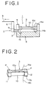
- Referring to Fig. 1, there is illustrated a conventional printing element using a laminated piezo-electric device. The printing element 1 is constituted by a
displacement magnifying mechanism 2, anactuator 3, abase member 4 linking thedisplacement magnifying mechanism 2 and theactuator 3, and amovable block 5. The displacementmagnifying mechanism 2 is constituted by anarmature 6, and a pair ofleaf springs armature 6. Theleaf spring 7 is fixedly secured to thebase member 4, while theother leaf spring 8 is fixedly secured to themovable block 5. A printing wire 9 is securely fixed to the other end of thearmature 6. - As best shown in the perspective view of Fig. 2, the
actuator 3 is constituted by a laminated piezo-electric device 10,blocks electric device 10 in such a manner as to sandwich the latter, andresilient plates 13a and 13b which are extended along the opposite sides of the laminated piezo-electric device 10 and welded to the latter by laser welding at the positions of points P while applying a predetermined compressive force to the laminated piezo-electric device 10. - The
blocks movable block 5 andbase member 4, respectively, by the use of an adhesive. Theblock 11 is linked to thebase member 4 through aleaf spring 15 for the purpose of stabilizing the operation of the laminated piezo-electric device 10. - The laminated piezo-
electric device 10 is constituted by a plural number of laminated piezo-electric ceramics layers, a plural number of internal electrodes which are sandwiched between the respective piezo-electric ceramics layers, a couple of external electrodes which are alternately connected to every other internal electrode, andlead wires external electrodes 13a and 13b, respectively. - Upon applying a drive voltage to the
lead wires electric device 10 is deformed to stretch by ten and several micrometers. As a result, themovable block 5 is pushed in the leftward direction in Fig. 1, and thearmature 6 is turned about its lower end portion by bi-metal action of theleaf springs movable block 5, thereby driving the printing wire 9 to protrude forward by several hundred micrometers. As a result, the wire 9 is hit against the platen, through an ink ribbon and a printing paper sheet which are not shown, to print a dot on the paper. - However, in case of the actuator of the above-described construction in which the
blocks electric device 10 are bonded to themovable block 5 andbase member 4 by means of an adhesive, there has been a problem that, due to insufficient strength of bondage, they are apt to be loosened or detached in the course of printing operations, failing to operate in a stable state in terms of performance quality. Especially, damages are more likely to occur on the part of the movable block which is subjected to bending stress in addition to tensile stress. - In accordance with an aspect of the present invention, there is provided a piezo-electric device type actuator constituted by: a laminated piezo-electric device including a plural number of laminated piezo-electric ceramics layers, a plural number of internal electrodes sandwiched between the respective piezo-electric ceramics layers, a first external electrode connected to alternate ones of the internal electrodes, and a second external electrode connected to the other alternate ones of the internal electrodes, the laminated piezo-electric device having first and second side surfaces on the opposite lateral sides thereof; a stationary base member; a pair of resilient plates extended along the first and second side surfaces of the laminated piezo-electric device, respectively, and each welded at one end to the base member; and a movable block welded to the other end of each of the resilient plates while applying a predetermined compressive force to the laminated piezo-electric device.
- In the piezo-electric device type actuator according to the present invention, the paired resilient members are fixedly welded to the movable block and base member to secure higher strength than the conventional fixation by an adhesive. As a result, it becomes possible to prevent damages as caused by shocks or vibrations when the movable block is displaced by application of a drive voltage to the laminated piezo-electric device. Accordingly, when used for a printing element, the piezo-electric device type actuator can ensure stabilized performance quality in printing operation.
- The above and other objects, features and advantages of the present invention and the manner of realizing them will become more apparent, and the invention itself will be best understood from a study of the following description and appended claims with reference to the attached drawings which show by way of example some preferred embodiments of the invention.
- In the accompanying drawings:
- Fig. 1 is a partly sectioned side view of a conventional printing element;
- Fig. 2 is a perspective view of a conventional piezo-electric device type actuator;
- Fig. 3 is a schematic sectional view of a printing head employing a piezo-electric device type actuator embodying the present invention;
- FIG. 4 is a perspective view showing the details in construction of the piezo-electric device type actuator according to the invention;
- Fig. 5 is a partly sectioned side view of a printing element employing the piezo-electric device type actuator according to an embodiment of the present invention; and
- Fig. 6 is a plan view of the piezo-electric device type actuator according to the embodiment of the invention.
- Hereafter, the invention is described more particularly by way of preferred embodiments with reference to the drawings.
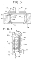
- Referring to Fig. 3, there is illustrated, in a schematic sectional view, a printing head incorporating a piezo-electric device type actuator according the present invention. The printing head is constituted by a plural number of
printing elements 20 which are mounted along the inner peripheral surface of abase member 26 of substantially cylindrical shape. Eachprinting element 20 includes adisplacement magnifying mechanism 22, a piezo-electricdevice type actuator 24, abase member 26 to which one end of the piezo-electricdevice type actuator 24 is fixedly connected, and amovable block 28 to which the other end of theactuator 24 is fixedly connected. - The
displacement magnifying mechanism 22 includes anarmature 30, and a pair of parallelly disposedleaf springs armature 30. Theleaf spring 32 is fixed to thebase member 26, while theother leaf spring 34 is fixed to themovable block 28. Thearmature 30 has aprinting wire 36 securely fixed to the other end thereof. - As best shown in Fig. 4, the piezo-electric
device type actuator 24 includes a laminated piezo-electric device 38 which is constituted by a large number of laminated piezo-electric ceramics layers 40 andinternal electrodes 42 sandwiched between the respective piezo-electric ceramics layers 40, a firstexternal electrode 44a disposed on one lateral side surface of the piezo-electric device 38 and connected to alternate ones of theinternal electrodes 42, and a secondexternal electrode 44b disposed on the opposite lateral side surface of the piezo-electric device 38 and connected to the other alternate ones of theinternal electrodes 42. Thereference numeral 46 denotes semi-cylindrical insulation layers which are formed between the firstexternal electrode 44a or the secondexternal electrode 44b and theinternal electrodes 42 to be insulated therefrom, thereby permitting alternate connections of the first and secondexternal electrodes internal electrodes 42. The firstexternal electrode 44a on the positive side is connected throughlead wire 54a to an anode terminal of a drive circuit, not shown, while the secondexternal electrode 44b on the negative side is connected throughlead wire 54b to thegrounded base member 26. - The laminated piezo-
electric device 38 is produced by laminating a plural number of green sheets of piezo-electric ceramics, each having a metal paste film formed on one side for formation of the internal electrode, and sintering the laminated sheets at a predetermined temperature for a predetermined time length. A pair ofresilient plates electric device 38, which are disposed perpendicularly between the lateral side surfaces with the first and secondexternal electrodes resilient plates block 48 provided at one end of the laminated piezo-electric device 38, and the other end securely fixed by laser welding to ablock 52 provided at the other end of the laminated piezo-electric device 38 while exerting a predetermined compression pressure to the latter. As shown in Fig. 4, the opposite ends of theresilient plates blocks - Referring to Figs. 5 and 6, the ends of the
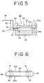
resilient plates block 48 are secured to themovable block 28 by laser welding while abutting theblock 48 against themovable block 28, and the other ends of theresilient plates base member 26 while abutting theblock 52 against thebase member 26. Namely, at the points indicated by the letter "W", theresilient plates base member 26,movable block 28 andblocks block 48 is connected to thebase member 26 through aleaf spring 56 to stabilize the operation of the laminated piezo-electric device. - According to the above-described embodiment, the
resilient plates blocks resilient plates base member 26 andmovable block 28, thereby ensuring connections of high strength of the laminated piezo-electric device 38 with thebase member 26 andmovable block 28. - Accordingly, as a drive voltage is applied to the
lead wires device type actuator 24, themovable block 28 is pushed out in the leftward direction in Fig. 5 due to distortion of the laminated piezo-electric device 38 in the stretching direction. This displacement of themovable block 28 is magnified through thedisplacement magnifying mechanism 22 for a printing operation by theprinting wire 36. At this time, even if a shock or vibration is applied to the joint portion between the laminated piezo-electric device 38 and thebase member 26 or themovable block 28, there is less possibility of a fracture or other damages occurring at the joint portions because the laminated piezo-electric device 38 is connected to thebase member 26 andmovable block 28 with higher strength as compared with the conventional bandage by an adhesive. Consequently, it becomes possible to obtain stabilized performance quality in printing operation. - Upon completion of a printing operation, the laminated piezo-
electric device 38 is de-energized, and theprinting wire 36 which has finished one printing action is returned to its initial position as a result of recovery of the laminated piezo-electric device 38. - Although the piezo-electric
device type actuator 24 has theblocks electric device 38 in the above-described embodiment, it is to be understood that the present invention is not restricted to such an arrangement. For example, if desired, there may be employed an arrangement in which theblocks electric device 38 is held in compressed state between thebase member 26 andmovable block 28, to which the opposite ends of theresilient plates - Further, although the piezo-electric device type actuator of the invention has been shown as an actuator for a printing element in the foregoing embodiment, it can be adopted in various other applications as an actuator serving for other purposes.
Claims (3)
- A piezo-electric device type actuator, comprising:
a laminated piezo-electric device including a plural number of laminated piezo-electric ceramics layers, a plural number of internal electrodes sandwiched between the respective piezo-electric ceramics layers, a first external electrode connected to alternate ones of said internal electrodes, and a second external electrode connected to the other alternate ones of said internal electrodes, said laminated piezo-electric device having first and second side surfaces on the opposite lateral sides thereof;
a stationary base member;
a pair of resilient plates extended along the first and second side surfaces of said laminated piezo-electric device, respectively, and each welded at one end to said base member; and
a movable block welded to the other end of each of said resilient plates while applying a predetermined compressive force to said laminated piezo-electric device. - A piezo-electric device type actuator as defined in claim 1, further comprising:
a first block interposed between said base member and one end of said laminated piezo-electric device, and securely welded to one end of each of said paired resilient plates; and
a second block interposed between said movable block and the other end of said laminated piezo-electric device, and securely welded to the other end of each of said paired resilient plates. - A piezo-electric device type actuator as defined in claim 1, wherein said first and second external electrodes are mounted on third and fourth lateral side surfaces of said laminated piezo-electric device disposed perpendicularly to said first and second lateral side surfaces, said first external electrode being connected to a drive circuit and said second external electrode being connected to the ground.
Applications Claiming Priority (2)
| Application Number | Priority Date | Filing Date | Title |
|---|---|---|---|
| JP3260926A JP2965763B2 (en) | 1991-10-09 | 1991-10-09 | Holding structure of piezoelectric actuator |
| JP260926/91 | 1991-10-09 |
Publications (3)
| Publication Number | Publication Date |
|---|---|
| EP0536637A2 EP0536637A2 (en) | 1993-04-14 |
| EP0536637A3 EP0536637A3 (en) | 1993-07-28 |
| EP0536637B1 true EP0536637B1 (en) | 1996-03-20 |
Family
ID=17354687
Family Applications (1)
| Application Number | Title | Priority Date | Filing Date |
|---|---|---|---|
| EP92116792A Expired - Lifetime EP0536637B1 (en) | 1991-10-09 | 1992-10-01 | Piezo-electric device type actuator |
Country Status (4)
| Country | Link |
|---|---|
| US (1) | US5289074A (en) |
| EP (1) | EP0536637B1 (en) |
| JP (1) | JP2965763B2 (en) |
| DE (1) | DE69209209T2 (en) |
Families Citing this family (12)
| Publication number | Priority date | Publication date | Assignee | Title |
|---|---|---|---|---|
| EP0569253B1 (en) * | 1992-05-08 | 1997-08-13 | Fujitsu Limited | Printing head |
| JP2806414B2 (en) * | 1992-08-18 | 1998-09-30 | 富士通株式会社 | Electromechanical transducer and printhead |
| US5777700A (en) * | 1993-07-14 | 1998-07-07 | Nec Corporation | Liquid crystal display with improved viewing angle dependence |
| JP3266031B2 (en) * | 1996-04-18 | 2002-03-18 | 株式会社村田製作所 | Piezoelectric resonator and electronic component using the same |
| US5994821A (en) * | 1996-11-29 | 1999-11-30 | Matsushita Electric Industrial Co., Ltd. | Displacement control actuator |
| DE19650900A1 (en) * | 1996-12-07 | 1998-06-10 | Bosch Gmbh Robert | Piezoelectric actuator |
| US6137747A (en) * | 1998-05-29 | 2000-10-24 | Halliburton Energy Services, Inc. | Single point contact acoustic transmitter |
| US6265810B1 (en) * | 2000-01-25 | 2001-07-24 | The Boeing Company | Piezoelectric support device |
| DE10055241A1 (en) * | 2000-11-08 | 2002-05-29 | Epcos Ag | piezo actuator |
| DE102004057795B4 (en) * | 2004-11-30 | 2006-12-28 | Siemens Ag | Contacting of multilayer piezoactuators or sensors |
| JP5030146B2 (en) * | 2007-02-14 | 2012-09-19 | Necトーキン株式会社 | Piezoelectric device for generating acoustic signals |
| JP2013101020A (en) * | 2011-11-08 | 2013-05-23 | Seiko Epson Corp | Sensor element, force detection device and robot |
Family Cites Families (8)
| Publication number | Priority date | Publication date | Assignee | Title |
|---|---|---|---|---|
| JP2556111B2 (en) * | 1988-10-20 | 1996-11-20 | ブラザー工業株式会社 | Piezoelectric motion converter |
| CA1319295C (en) * | 1988-03-18 | 1993-06-22 | Akio Yano | Printing head of wire-dot impact printer |
| CA1331313C (en) * | 1988-07-08 | 1994-08-09 | Akio Yano | Printing head of wire-dot impact printer |
| JPH0681718B2 (en) * | 1988-07-27 | 1994-10-19 | ブラザー工業株式会社 | Piezoelectric motion converter |
| EP0396872B1 (en) * | 1989-03-16 | 1995-06-28 | Fujitsu Limited | Apparatus for driving printing head of wire-dot impact printer |
| JP2864554B2 (en) * | 1989-09-05 | 1999-03-03 | ブラザー工業株式会社 | Method of assembling piezoelectric element in motion conversion device for piezoelectric element |
| JP2976340B2 (en) * | 1990-02-19 | 1999-11-10 | 富士通株式会社 | Multilayer piezoelectric element |
| US5089739A (en) * | 1990-03-19 | 1992-02-18 | Brother Kogyo Kabushiki Kaisha | Laminate type piezoelectric actuator element |
-
1991
- 1991-10-09 JP JP3260926A patent/JP2965763B2/en not_active Expired - Fee Related
-
1992
- 1992-09-30 US US07/953,662 patent/US5289074A/en not_active Expired - Lifetime
- 1992-10-01 EP EP92116792A patent/EP0536637B1/en not_active Expired - Lifetime
- 1992-10-01 DE DE69209209T patent/DE69209209T2/en not_active Expired - Fee Related
Also Published As
| Publication number | Publication date |
|---|---|
| EP0536637A3 (en) | 1993-07-28 |
| JPH0596755A (en) | 1993-04-20 |
| US5289074A (en) | 1994-02-22 |
| EP0536637A2 (en) | 1993-04-14 |
| DE69209209D1 (en) | 1996-04-25 |
| DE69209209T2 (en) | 1996-07-25 |
| JP2965763B2 (en) | 1999-10-18 |
Similar Documents
| Publication | Publication Date | Title |
|---|---|---|
| EP0536637B1 (en) | Piezo-electric device type actuator | |
| EP0065784B1 (en) | Lever actuator comprising a longitudinal-effect electroexpansive transducer and designed to prevent actuation from degrading the actuator | |
| EP1796256B1 (en) | Piezoelectric device and piezoelectric switch employing same | |
| EP0320996B1 (en) | Mechanical amplification mechanism for piezoelectric elements | |
| US11393972B2 (en) | Multi-layer piezoelectric ceramic component and piezoelectric device | |
| US5005994A (en) | Printing head of wire-dot impact printer | |
| EP0488232B1 (en) | An electrostrictive actuator | |
| JP3262078B2 (en) | Inkjet recording head | |
| EP0350258B1 (en) | Dot matrix printing heads | |
| KR860000749B1 (en) | Printer head | |
| US5292201A (en) | Printing head of wire-dot impact printer | |
| JPS5945165A (en) | Impact type printing head | |
| JPS58163669A (en) | Impact printer head | |
| JPH0253230B2 (en) | ||
| JPS5916767A (en) | Printing unit | |
| JP2003324223A (en) | Laminated piezoelectric element | |
| JP2893739B2 (en) | Electrostrictive effect element | |
| JP3468043B2 (en) | Multilayer piezoelectric transformer | |
| JPH0364313B2 (en) | ||
| JPH04251755A (en) | Piezoelectric actuator and manufacture of piezoelectric actuator | |
| JPH0442192B2 (en) | ||
| JPH0373467B2 (en) | ||
| JPH0575174A (en) | Manufacture of piezoelectric element type actuator | |
| JPH0541881Y2 (en) | ||
| JPH0132750Y2 (en) |
Legal Events
| Date | Code | Title | Description |
|---|---|---|---|
| PUAI | Public reference made under article 153(3) epc to a published international application that has entered the european phase |
Free format text: ORIGINAL CODE: 0009012 |
|
| AK | Designated contracting states |
Kind code of ref document: A2 Designated state(s): DE GB IT |
|
| PUAL | Search report despatched |
Free format text: ORIGINAL CODE: 0009013 |
|
| AK | Designated contracting states |
Kind code of ref document: A3 Designated state(s): DE GB IT |
|
| 17P | Request for examination filed |
Effective date: 19940108 |
|
| 17Q | First examination report despatched |
Effective date: 19950413 |
|
| GRAA | (expected) grant |
Free format text: ORIGINAL CODE: 0009210 |
|
| AK | Designated contracting states |
Kind code of ref document: B1 Designated state(s): DE GB IT |
|
| REF | Corresponds to: |
Ref document number: 69209209 Country of ref document: DE Date of ref document: 19960425 |
|
| ITF | It: translation for a ep patent filed |
Owner name: STUDIO JAUMANN |
|
| PLBE | No opposition filed within time limit |
Free format text: ORIGINAL CODE: 0009261 |
|
| STAA | Information on the status of an ep patent application or granted ep patent |
Free format text: STATUS: NO OPPOSITION FILED WITHIN TIME LIMIT |
|
| 26N | No opposition filed | ||
| REG | Reference to a national code |
Ref country code: GB Ref legal event code: IF02 |
|
| PGFP | Annual fee paid to national office [announced via postgrant information from national office to epo] |
Ref country code: DE Payment date: 20081014 Year of fee payment: 17 |
|
| PGFP | Annual fee paid to national office [announced via postgrant information from national office to epo] |
Ref country code: IT Payment date: 20081028 Year of fee payment: 17 |
|
| PGFP | Annual fee paid to national office [announced via postgrant information from national office to epo] |
Ref country code: GB Payment date: 20081001 Year of fee payment: 17 |
|
| PG25 | Lapsed in a contracting state [announced via postgrant information from national office to epo] |
Ref country code: DE Free format text: LAPSE BECAUSE OF NON-PAYMENT OF DUE FEES Effective date: 20100501 |
|
| PG25 | Lapsed in a contracting state [announced via postgrant information from national office to epo] |
Ref country code: GB Free format text: LAPSE BECAUSE OF NON-PAYMENT OF DUE FEES Effective date: 20091001 |
|
| PG25 | Lapsed in a contracting state [announced via postgrant information from national office to epo] |
Ref country code: IT Free format text: LAPSE BECAUSE OF NON-PAYMENT OF DUE FEES Effective date: 20091001 |