EP0536357B1 - Procede et dispositif d'aide a l'inspection d'un corps, notamment pour la tomographie - Google Patents
Procede et dispositif d'aide a l'inspection d'un corps, notamment pour la tomographie Download PDFInfo
- Publication number
- EP0536357B1 EP0536357B1 EP92908376A EP92908376A EP0536357B1 EP 0536357 B1 EP0536357 B1 EP 0536357B1 EP 92908376 A EP92908376 A EP 92908376A EP 92908376 A EP92908376 A EP 92908376A EP 0536357 B1 EP0536357 B1 EP 0536357B1
- Authority
- EP
- European Patent Office
- Prior art keywords
- critical
- space
- image
- real space
- contours
- Prior art date
- Legal status (The legal status is an assumption and is not a legal conclusion. Google has not performed a legal analysis and makes no representation as to the accuracy of the status listed.)
- Expired - Lifetime
Links
Images


Classifications
-
- G—PHYSICS
- G06—COMPUTING; CALCULATING OR COUNTING
- G06T—IMAGE DATA PROCESSING OR GENERATION, IN GENERAL
- G06T11/00—2D [Two Dimensional] image generation
- G06T11/003—Reconstruction from projections, e.g. tomography
- G06T11/006—Inverse problem, transformation from projection-space into object-space, e.g. transform methods, back-projection, algebraic methods
-
- Y—GENERAL TAGGING OF NEW TECHNOLOGICAL DEVELOPMENTS; GENERAL TAGGING OF CROSS-SECTIONAL TECHNOLOGIES SPANNING OVER SEVERAL SECTIONS OF THE IPC; TECHNICAL SUBJECTS COVERED BY FORMER USPC CROSS-REFERENCE ART COLLECTIONS [XRACs] AND DIGESTS
- Y10—TECHNICAL SUBJECTS COVERED BY FORMER USPC
- Y10S—TECHNICAL SUBJECTS COVERED BY FORMER USPC CROSS-REFERENCE ART COLLECTIONS [XRACs] AND DIGESTS
- Y10S378/00—X-ray or gamma ray systems or devices
- Y10S378/901—Computer tomography program or processor
Definitions
- the invention relates to the inspection of a body using wave beams coming out of it. It applies more particularly, but not exclusively, with tomography.
- each raw data signal represents the intensity of a given type of wave beam, which leaves the body along an axis called "acquisition line".
- the axis in question can be designated by at least two parameters (like a position parameter and an angular parameter).
- the raw data define a "image of the projections" of the radiation, in a multidimensional space which is called “projection space”. It's a dual space of real space (physical observation space), because at each point in the projection space there corresponds a right and only one of the actual space.
- the computed tomography is based on the following principle: if we have a sufficiently large set of raw data, relating to acquisition lines that cross the body in different directions then it has to be possible to find the variation in absorption (or emission) of the wave beam at each point of the body studied.
- An essential aim of the present invention is, on the contrary, to provide means that facilitate the real-time use of information captured.
- a second object of the invention is to allow this use information captured from the level of the projection image, that is to say without necessarily having to convert them into "reconstructed" data in real space.
- a third object of the invention is to provide results to from a restricted set of raw data, while the prior art in principle requires knowledge complete with this data.
- a fourth object of the invention is to provide more effective results. precise than before, regarding internal surfaces or of the body examined.
- the invention also aims to allow not only the treatment not only absolute measures, but also that of "differential” measures, obtained from the level of the sensors.
- the invention also aims to allow direct control of a body intervention apparatus, particularly in time real.
- the invention still paves the way for dynamic tracking of objects, there again because of its potential to operate in real time.
- the invention first of all offers an aid device to the inspection of a body.
- This device will acquire a ordered set of data signals raw, as defined above.
- the processing means include means for differential analysis of raw data signals relative to their axis parameters, to determine critical points where a signal strength jump occurs captured.
- each of these points corresponds to a line acquisition tangent to an internal (or external) border of the body examined.
- Axis parameters of critical points then represent, as a whole, the position of a part at least from the borders of the body.
- the present invention therefore relates to an apparatus and a method for determination of the internal and external surfaces of a body, examined by means of wave beams.
- CT Computed tomography
- the present invention is distinguished by the fact that it makes it possible to determine directly and very precisely internal or external surfaces of the body examined, called “characteristic surfaces”, where a significant change in the properties of the body, without that it is necessary to reconstruct a digital image representing the variation in absorption inside this latest.
- Figure 1 an acquisition device (1), consisting of a plurality of sensors measuring the raw signals.
- these represent the intensity of the beam of examination waves (or “auscultation beam”) which reaches the sensor in a specific direction.
- the position torque of the sensor / acquisition direction is comparable to a line right called "acquisition line".
- the invention uses signals drawn from such an acquisition device, signals it processes (2, Figure 1) using a unit Calculation.
- the acquisition device (1) itself is not necessarily physically incorporated into the device according to the invention. But the way raw data is acquired influences the treatment according to the invention.
- Figure 2 illustrates an exemplary embodiment of the apparatus acquisition, in the case where beams are emitted parallels O1.,. Oi ... On, crossing body B in a straight line, to reach sensors C1 ... Ci ... Cn, placed in line on a line segment of length 1, located at a distance d from the center O of the device.
- parallel wave beams O1 ... Oi ... We often consist of a single beam of waves planes, forming an angle Q with a reference direction.
- This beam of plane waves and the line of sensors are in common rotation around the center O of the device.
- the angle Q indicates the direction of incidence of the beam, which is also the direction perpendicular to the sensor line.
- FIG 3 illustrates another embodiment of the apparatus acquisition.
- the different wave beams O1 ... Oi ... We are in a "fan", and the sensors C1 ... Ci ... Cn are placed on a circular support.
- Each sensor is designated by its curvilinear abscissa Ui along the circular support.
- the fan beams O1 ... Oi ... We are often made up of a single beam of spherical waves.
- the system is mobile in rotation around the center O of the support circular.
- the angle Q is then taken between a direction of reference and central axis of the beam (in bold in the figure), defined by the point of emission of the spherical wave beam and by the center of rotation of the device.
- the Oi beam arrives on this sensor with an angle Qi equal to Q (with variable Q as a function of time), plus a function of Ui which does not depend time. (An example of this will be described later, about Figure 22).
- the angle parameter Q has the same meaning in real space and the space of projections, because in both cases it represents the direction of the acquisition line; on the other hand, the parameter (s) of position of the sensors (U, V) have no direct relationship with the positions (x, y) of the points considered in real space.
- the invention aims to determine characteristic surfaces or "boundaries" of the body examined in real space by performing extraction or reinforcement of contours directly in space projections, then a follow-up of contours.
- geometric tomography performs also this contour tracking directly in the space of projections.
- the present invention makes it possible in particular to avoid the long step and expensive computed tomography when the goal is to determine the characteristic surfaces of the body, rather than obtain a digital image representative of the variation in absorption coefficients of this body.
- the invention provides position information to the less as good as those of the computed tomography. She allows better accuracy for tangent information and curvature of the characteristic surfaces of the body.
- the geometric tomography technique is based on observation following, described in connection with FIGS. 6A, 6B and 7:
- FIG. 6B shows a surface S, called “characteristic”, locally delimiting, inside the body examined, two zones A1 and A2 neighbors whose interaction properties with auscultation beams vary significantly and other of S.
- This significant variation in properties interaction can be a sudden change in index, a sudden change in the absorption coefficient, a sudden variation of the quantity of waves emitted or re-emitted, by example.
- FIGS. 8A and 8B show a first example of correspondence between real space and projection space, for a fully convex surface SD (disc).
- Figure 8B space real, the abscissa axis designates the position U of the sensors.
- the curve Ui at the bottom of the figure (in fact, discrete), for Q 0, Q designating the angular position of the sensor line by compared to the vertical.
- the result ( Figure 8A) is a ribbon delimited by two critical contours CC1 and CC2, between the angles 0 and two pi (360 ° angular).
- the Figure 8A also shows that the gradients G1 and G2 allow to distinguish the interior (hatched areas) and the exterior.
- the data signals raw are expressed in differential form.
- This variant of the device may consist in providing for the reinforcement of the outlines inside the camera near the sensors.
- Each signal received no longer corresponds to the measurement of the intensity of the incident wave beam but to a measurement intensity differential for a pair of neighboring sensors, or for the same sensor between two different times.
- FIG. 9 An exemplary embodiment (FIG. 9) consists in using pairs of sensors Ci1 and Ci2, each pair of sensors providing two electrical signals including the difference in intensity is processed using an operational amplifier 191 mounted as a subtractor.
- This type of device will be called “spatial differentiation device”. It generates directly the value of the component Gu of the gradient vector of the image of the projections, in the spatial direction "U” in the case of a device corresponding to Figure 2 or 3. It is not no need to double the number of sensors; the couple Ci1 and Ci2 can be defined each time by two neighboring sensors Ci and Ci + 1.
- the time differentiation device is used to directly generate the signals corresponding to the gradient of the image of the projections according to the dimension angular Q.
- the camera can then be equipped with both temporal and spatial differentiation devices (as in Figure 10), so as to directly generate signals corresponding to the different components of the vector gradient (spatio-temporal), according to each of the coordinates or dimensions of the image of multi-dimensional projections.
- An additional device (193,194) also makes it possible to transform by composition the signals corresponding to components of the gradient along the various dimensions in signals corresponding to the modulus of the gradient vector G and to the direction of this gradient vector G. These signals are then treated in a manner described later.
- the invention tracks of contours inside the image of the projections.
- Contour tracking is the means here to determine in the space of projections of "critical forms" (thus called because they can be critical lines or surfaces which are an estimate of the critical contours.
- the tomography direct geometric plans to transform critical shapes of the space of projections in "reconstructed forms" in real space, now corresponding to characteristic surfaces of the body examined.
- the raw signals measured at each time interval are grouped according to the position of the sensor, and the management of the acquisition line, at the time of acquisition.
- each box of which will contain a representation of the measurement of the intensity of the wave beam at a given instant following an acquisition line: each box corresponds to a acquisition line with a different position or direction.
- the technique in question does not necessarily use all raw signals (received). It is also applicable to a subset of the raw signals received, for example those belonging to a restricted neighborhood around a specific point of the image of the projections.
- this table is hereinafter called “projection image”, although it may, at a given time, contain only part of this picture.
- the projection image has one dimension spatial U, which corresponds to the position of the detectors along of the detector line, and an angular dimension Q, which corresponds to the angle of view.
- FIG. 4 shows how the image of the projections is constituted, by concatenation of mono-dimensional projections, in the case of the shooting devices of FIGS. 2 or 3.
- the projection image will include two spatial dimensions U, V which correspond to the position of sensors on their support surface, and a corresponding Q dimension at the angle of view.
- the image of the projections can have four dimensions: two spatial dimensions U, V and two angular dimensions Q, Z.
- the space multi-dimensional corresponding to the image of the projections sera called the projection space.
- edge enhancement is the calculation of the gradient or the Laplacian of the image.
- This step provides a multi-dimensional computer table as output. corresponding to the image of projections with contours reinforced.
- Variants of this type of treatment (Chapter 3 "Early processing "already mentioned) also work on images multi-dimensional larger than two, which allows to deal with the case of an image of dimension projections greater than two.
- the expression “critical form” indifferently designates a line or a critical surface.
- an algorithm for tracking contour is applied in the image of the projections so as to determine the lines corresponding to the critical contours in this image, that is, where a variation occurs significant intensity. (In the case of a projection image of dimension greater than two, we then determine critical surfaces).
- the processing device therefore supplies the output (62, FIG. 11) a geometric description of the characteristic surfaces or "borders" of the body, which can be used for visualization, medical diagnosis, measurement of characteristics geometric measures such as length, area or volume of body parts studied, the guidance of a prosthesis construction, intervention planning surgical, guiding a device intervening on the body reviewed, and many other applications.
- the algorithmic transformation starts from the observation that a point in the projection space corresponds to a line acquisition in real space, similar to a straight line, and tangent to the characteristic surface that we want to reconstruct.
- the means used consists in treating all the lines together critics belonging to the same plane in real space, called “cutting plane” (step 130). In the case of an acquisition system of the type of that of figure 2 or 3, this condition is carried out for all acquisition lines; in the others In this case, the information must be extracted selectively.
- Each point Pk is designated by axis parameters Uk and Qk, and a vector is associated with it gradient Gk.
- the point Pk corresponds to it in real space a straight line Lk (the acquisition line), located in the cutting plane (step 131). Because the point Pk belongs to a critical line, the line Lk is tangent to the characteristic surface S that we want to reconstruct.
- the direction of the vector gradient Gk (determined in 133) in the image of the projections makes it possible to distinguish the two half-planes delimited by the line Lk in the cutting plane (134).
- the direction of the gradient (G1 for P1 and L1) defines a side with respect to the critical line F. It corresponds to it, in real space, one side with respect to the acquisition line L1.
- the half-plane lying on this side of L1 will be called the interior half-plane DPin, the other being called DPex exterior half-plane.
- characteristic line The intersection of the characteristic surface S (to be reconstructed) and of the section plane (considered, here the plane of figure 12) defines a line of real space, included in the section plane, and which we will call "characteristic line”.
- the means proposed to determine this "characteristic line” consists in calculating polygonal lines corresponding to convex or concave parts of the characteristic lines. These polygonal lines are calculated as the outline of the intersection of a consecutive series of half-planes all interior, or all exterior (step 136). This works (137, 139) until exhausting the list of Pk points, or until a change concavity, if applicable.
- any function U f (Q), defining a line critical, corresponds to a fully convex part or fully concave of the surface to be reconstructed.
- a way to determine the pieces of sinusoids approximating the critical outline is to use the Hough method (see chapter 4 of the COMPUTER VISION book already mentioned, in particular paragraph 4.3) for sinusoids, from the image of projections.
- This transformation makes it possible to determine for each point P of a critical form F of the space of projections (150), a point R of real space belonging to the characteristic surface S corresponding.
- the formula is obtained by considering an infinitesimal displacement around the point P belonging to a critical form F in projection space.
- the point and the moved point correspond with two acquisition lines in real space.
- point R is the intersection of these two lines when the value of the displacement tends towards 0.
- the coordinates of the point R are calculated by an expansion limited of F around point P.
- the simplest form is slope of the function f (Q) at point P (block 154).
- Step 156 in deduces the coordinates (x, y) of the point R of the characteristic surface S in real space.
- FIG. 16 An example of a local transformation formula, in the case of an acquisition system of the type of that of FIG. 2 is illustrated by FIG. 16.
- x and y are the coordinates of the point R reconstructed in the section plane
- the function f () defines a critical line F in the image of the projections, with Q the angle of view
- U f (Q ) the position of the sensor along the rotating line.
- (U, Q) are the coordinates of point P in the image of the projections and f () is the equation of the critical line F.
- Q gives the direction of the tangent to the surface characteristic S in R.
- the reconstruction accuracy depends on the accuracy with which we succeed in determining f (Q), therefore the precision of the followed by the contours of the previous step (c), but also the accuracy of determining the slope of the function f at point Q (improved accuracy according to the invention).
- the rear projection method (figure 17) consists first of all in define (170) a discretization table or grid T (x, y) in real space, initialized for example to 0.
- T (x, y) is incremented (176) of a value associated with the point of the critical form and called "confidence coefficient" (assumed to simplify equal to 1 in the drawing).
- This confidence coefficient reflects the confidence we place in to the fact that this point of the critical form does belong to a critical outline.
- the confidence coefficient can be taken from the value of the gradient module of the image of projections at the point considered.
- the discretization grid therefore corresponds to a two-dimensional image when we are interested in a section of the body examined (or three-dimensional in the general case), for which the the value contained in each box will be all the more important that we are likely to be on a characteristic surface of the body examined.
- a contour tracking (178) is then applied again, this times in real space, so as to find the line (or the surface) of the actual space corresponding to a characteristic surface of the body (179).
- Geometric reciprocal tomography differs from processes classics by the fact that it uses the image of projections to calculate the update of the characteristic surface (estimated) in real space.
- the calculation of the dual form is immediate for all the points of the form in real space for which we can calculate the direction of the tangent if it is a line, or for which we can calculate the tangent plane, if it is a area.
- a variant consists in performing the smoothing on F'0 in the space of the projections before transformation into S'0.
- Another variant consists in imposing rigidity criteria to the Fi or Si forms used, by seeking for example to minimize the curvature of these shapes.
- step (90) If the number of iterations performed exceeds a number of iterations fixed p, or if the error residue becomes less than one fixed threshold, the form Sp obtained is considered to be a sufficient approximation of S, and becomes the result of the process. Otherwise, we are brought back to step (90), where we replace S0 by the new S1 form that we got.
- curve S0 is represented by a list chain of points, each point being defined by a triplet (x, y, Q) where (x, y) are the coordinates of the point in real space and Q the angle which indicates the direction of the tangent (and by therefore from normal) to S0 at this point.
- the displacements are: dU, and dQ times the modulus of the vector OR, where modulus of OR is (x 2 + y 2 ) 1/2 .
- S1 is obtained from S'0, by smoothing the values (x ', y', Q ') of the curve S'0, taking into account a criterion of continuity concerning the position of the points and the direction tangents.
- the reciprocal geometric tomography process therefore allows improve the placement of the estimated surfaces in relation to real characteristic surfaces of the body studied, and to follow displacements and deformations of these surfaces during the time.
- the final position P [t] is a compromise between the position of a point P "[t] extrapolated from the form S [t-dt], and the position of point P '[t] obtained by searching for the critical contour closest in the projection space. Weighting between positions P "[t] and P '[t] is adjusted to adjust the degree of smoothing of the curves S [t] as desired.
- the reciprocal geometric tomography process therefore makes it possible to determine for each time interval dt a new curve S [t] representing a characteristic surface of the body examined. It allows real-time tracking of trips and deformations of this surface.
- the method makes it possible to update the position of the curve over 1 / 256th of its length in 1 / 25th second.
- the method only requires the measurement of a few sensors only around the position obtained on the turn previous, which allows for example to reduce the swept area by the auscultation beams, and by the same token the quantity of waves received by the body examined.
- Another object of this invention relates to an apparatus for real-time monitoring of movements or deformations of characteristic surfaces of the examined body evolving during the time.
- the invention makes it possible to update very quickly the position of the characteristic surfaces between a shot and the next.
- the device consists of a shooting device and a calculator.
- the shooting device is similar to one of those described above, and the computer performs a program corresponding to the geometric tomography process reciprocal.
- Another object of this invention is to provide an apparatus and an intervention process allowing to act inside a body using one or more beams of waves called “active wave beams", each active beam is focused in a precise direction, similar to a straight line and called “line of action”. These active beams are arranged way to go through a specific point of the body, called “point target ".
- the invention is characterized by the fact that it uses, to plan the guidance of active beams, lines or critical surfaces defined in the projection space and corresponding to the critical contours associated with surfaces characteristics of the treated body.
- the object of the invention is to prevent active beams from entering inside regions delimited inside the body, and called “zones protected ".
- the mobile support is capable of moving in rotation around its center C, in a plane called "plane of rotation ".
- a device also makes it possible to vary the direction of the plane of rotation over time by making rotate the plane of rotation about an axis A contained in the horizontal plane passing through the center of rotation C. Rapid movement of the mobile support reduces the amount of waves received by the body in the peripheral zones of the body, and concentrate it at the center of rotation C.
- the quantity of waves received per unit of time is inversely proportional to the distance from the center of rotation C, in the plane of rotation.
- Each line of action is identified using two angles (Q, Z).
- Z indicates the angle between the plane of rotation PR and the plane horizontal.
- Q indicates the angle between the line of action in the plane of rotation, and axis A.
- the control law Q (t) can be a rotation at constant speed w.t, a pendulum movement, or any movement.
- a device also allows the relative movement of the body treated with respect to the center of rotation C, either by displacement of body B, either by moving the device.
- the settings intervention device control are therefore the speed of rotation w, the angle of the rotation plane Z (possibly, a other angle), and the three relative positions (x, y, z) of the body relative to the center of rotation, plus possibly three body direction coordinates.
- Some processing devices do positioning by a stereotaxis device, which determines the position relative of the target point with respect to the body treated, and therefore to bring the target point to the center of rotation of the device in acting on the commands (x, y, z), possibly on the angle controls.
- Device memory contains description characteristic surfaces of the treated body, obtained by example by the geometric tomography process.
- the memory of the device also contains the surface data defining the areas of the body to be protected.
- the projection space will be made up of three dimensions "U, Q, Z" each point of which corresponds to a line in space real.
- the angular dimensions "Q, Z” correspond to the angles Q and Z already mentioned.
- the additional dimension U (figure 22) makes it possible to represent oriented straight lines passing through two points P1 and P2 of the support circular, but not necessarily passing through the center of rotation C as follows: the angle Q represents the direction (P1, C). Point P'2 is the point of the circular support symmetric of P1 with respect to C. The distance U is the abscissa curvilinear (along the circular support) of P2, counted at from point P'2.
- the couple (U, Q) therefore defines so single oriented straight cutting the circular support in half points.
- the calculation unit is programmed to transform the real space surfaces in projection space surfaces (U, Q, Z).
- a volume in real space turns into a volume in the projection space.
- the protected areas appear in the plan (Q, Z) as elements of surfaces.
- a line of action of a active beam corresponds to a point belonging to the plane (Q, Z), called dual point associated with the active beam, whose position changes over time according to the piloting law.
- the calculation unit allows establish the times when each active beam should be activated or disabled, simply by checking whether the associated dual point the active beam is inside or outside a protected area.
- One way to perform this test is to calculate once and for all a digital image corresponding to the rectangle of the plane (Q, Z) limited to values between 0 and 2P.
- Figure 23 concerns the simplified case where one does not vary the angle Z.
- the projection image has only two dimensions U and Q.
- the two contours Fp delimit, in the space of projections, the area or object to be protected in body B.
- the neighborhood of U Ua in figure 23 indicates the zone beam activity in the projection space. This SG neighborhood is delimited by two parallel verticals.
- the area delimited by the two critical contours Fp (associated to the characteristic surfaces of the treated body) intersects said neighborhood SG in two ranges PL1, PL2 which determine the instants to which the active wave beam is to be deactivated, so not to enter protected areas of the body.
- the intervention process which is also part of this invention, therefore consists in determining the trajectory of a active beam so as to prevent this beam from entering inside prohibited areas of space,
- This process is characterized by the fact that it uses a representation of the body treaty and protected areas in a space called "space of projections ", where each point represents a line in space real, and in which the set of action lines that can cover the active beam can be shown.
- An exemplary embodiment of this method consists in determining for each characteristic surface of the body of real space, a line or a critical surface in the space of the projections, formed by the locus of the lines tangent to the critical surface.
- the associated critical surface is oriented so that define an interior and an exterior. Has a line of action corresponds to a point in the projection space called dual point associated with the active beam.
- the intervention process consists in determining paths in the projection space for which the dual point associated with active beam is always located outside of all critical areas defining protected areas.
- the intervention process establishes the moment when the active beam must be deactivated and reactivated.
- the bundle is represented as a disc in the space of projections called "dual spot associated with the active beam” if this one is dimension two.
- the trajectory of the dual spot defines a ribbon in the projection space, which corresponds to a vertical strip when the target point is located in the center rotation of the device (figure 23).
- the dual spot may be approximated by a "hyper-sphere" in the general case.
- One way to carry out this intervention process is to calculate a digital image called "synthetic projection image", having the same dimensions as the projection space, and where each box contains information relating to the whole points of the body intersected by the corresponding line at the point considered in the projection space.
- An example is to create a digital image where each box indicates by a binary value if the line of real space or not intersects a protected area.
- Another example is to associate a value with each box of this synthetic projections image, value which, if it is strictly positive, is decremented each time the stain dual pass through this box, and which, if negative or null, indicates that the active beam must be deactivated.
- This value somehow represents a "write-off credit" which decreases each time the active beam takes a direction very close to the direction corresponding to this box in the image synthetic projections.
- Another way of carrying out the intervention process concerns a different way to get the critical contours in the projection space "E1" relating to the intervention apparatus.
- Another object of this invention is the definition of an apparatus and an intervention method making it possible both to follow the displacements of critical surfaces and act at a specific point, called "target point" of the body treated with beams active waves all passing through this target point.
- the device has the same characteristics as the device previously described.
- the center O is the target point of the body B.
- the device also includes a calculation unit and a memory (not shown in Figure 24).
- Figure 25 illustrates what is happening in the projection space.
- the acquisition device updates the definition of these areas.
- the intervention apparatus is associated with a parameter Ua, around which a SG neighborhood (dual spot associated with the active beam), as previously. At the instant considered, it is at the angle Qj. If the dense hatched area is to be treated, the intervention beam is only activated when the vicinity of point Ua, Qi is found in this area.
- the critical contours are determined in time real in the image of the projections I, and each point of the contour review is updated at each turn of the acquisition device, which allows to follow the movements of the body during of the intervention.
- the relative position of the dual spot (s) associated with active beams also makes it possible to determine in time actual activation or deactivation orders, piloting of active beams, or of refocusing orders of the body treated so as to always maintain the target point at focus center for active beams.
- This device and this process therefore make it possible to intervene in a point of a moving body over time.
- This variant generates, directly in real space, a "gradient image" of a section of the body under consideration. She is characterized by the fact that the contours are reinforced in the image of the projections, as before, while a rear projection is then carried out to pass into space real, where you can follow contours.
- the starting point (step 260, figure 26) is the constitution of the image of the projections, now noted IP1 [Q, U]. (To lighten the notations, we use the square brackets for the variables whose depends on a function).
- the invention uses the component according to the U coordinate of the gradient of the image IP2, denoted IP3, and defined by the formula (IV).
- IP3 it is therefore possible to calculate IP3 in a very simple way and fast, and moreover by treating only one line at a time IP1, at constant Q, as it arrives from the acquisition device.
- this filtered rear projection method allows to move from the projection image, where Q is the angle of incidence rays and U the coordinate of the detector along the detector line, to a digital image of gradients in real space.
- IR [x, y] is a contour image which can be used to give a first approximation for geometric tomography reciprocal.
Landscapes
- Physics & Mathematics (AREA)
- Engineering & Computer Science (AREA)
- General Physics & Mathematics (AREA)
- Theoretical Computer Science (AREA)
- Algebra (AREA)
- Mathematical Analysis (AREA)
- Mathematical Optimization (AREA)
- Mathematical Physics (AREA)
- Pure & Applied Mathematics (AREA)
- Analysing Materials By The Use Of Radiation (AREA)
- Apparatus For Radiation Diagnosis (AREA)
- Force Measurement Appropriate To Specific Purposes (AREA)
Description
- la Figure 1 est le schéma général d'un appareil de tomographie;
- la Figure 2 est le schéma de fonctionnement d'un appareil d'acquisition uni-dimensionnel à ondes parallèles;
- la Figure 3 est le schéma de fonctionnement d'un appareil d'acquisition uni-dimensionnel à ondes sphériques;
- la Figure 4 est un schéma géométrique illustrant la constitution de l'image des projections, à partir de projections uni-dimensionnelles;
- la Figure 5 est un schéma général d'un dispositif selon la présente invention;
- les Figures 6A et 6B sont des figures géométriques illustrant respectivement une variation d'intensité dans l'image des projections et l'allure d'une "surface caractéristique" correspondante dans l'espace réel;
- la Figure 7 illustre une "surface caractéristique" S, en tant qu'enveloppe de droites;
- Les figures 8A et 8B, respectivement 8C et 8D montrent deux exemples de correspondance entre l'espace réel et l'espace des projections;
- la Figure 9 est un schéma plus détaillé d'une variante selon la présente invention dans l'acquisition des données brutes;
- la Figure 10 est un schéma plus détaillé d'un dispositif de tomographie géométrique directe selon la présente invention;
- la Figure 11 est le schéma des étapes du procédé de tomographie géométrique directe selon l'invention;
- la Figure 12 est un schéma géométrique illustrant la reconstruction d'une approximation polygonale de la surface par intersection de demi-plans;
- la Figure 13 est un schéma fonctionnel d'une technique dite "transformation algorithmique";
- la Figure 14 est un schéma fonctionnel d'une technique dite "transformation géométrique globale";
- la Figure 15 est un schéma fonctionnel d'une technique dite "transformation géométrique locale";
- la Figure 16 est un schéma géométrique illustrant l'usage d'une telle formule géométrique locale de transformation;
- la Figure 17 est un schéma fonctionnel d'une technique dite "rétro-projection";
- la Figure 18 est le schéma fonctionnel du procédé de tomographie géométrique réciproque selon l'invention;
- la Figure 19 est un schéma géométrique illustrant l'amélioration de la position par une transformation locale opérant sur les déplacements;
- la Figure 20 est un schéma géométrique illustrant la mise à jour dynamique de la courbe par utilisation de données locales;
- la Figure 21 est le schéma d'une variante concernant un appareil d'intervention à faisceau d'ondes actif;
- la Figure 22 est un schéma géométrique illustrant l'introduction d'un paramètre u;
- la Figure 23 est un schéma géométrique illustrant la génération des ordres d'activations du faisceau d'ondes actif à partir des contours critiques dans l'espace des projections;
- la Figure 24 est le schéma de principe d'un appareil d'intervention possédant à la fois une source d'ondes d'auscultation et un faisceau d'ondes actif;
- la Figure 25 est un schéma géométrique illustrant le procédé d'intervention utilisé pour générer les ordres d'activation, allié à un suivi dynamique des lignes de contour critique; et
- la Figure 26 est un schéma fonctionnel d'une autre variante intéressante de réalisation.
- dans un premier mode, les capteurs et la source des faisceaux d'auscultation se trouvent placés sur un support constituant le dispositif de prise de vue de part et d'autre du corps étudié. Les faisceaux d'auscultation pénètrent à l'intérieur du corps et sont absorbés en fonction des coefficients d'absorption de la matière composant le corps étudié. Les lignes d'acquisition sont définies comme étant les droites reliant la source aux capteurs.
- dans un second mode de réalisation, la source des faisceaux d'ondes n'est plus placée à l'extérieur du corps, mais c'est le corps lui même qui émet les faisceaux d'ondes. Les capteurs permettent de mesurer l'intensité de ces faisceaux d'ondes, chacun selon une direction précise, soit par collimation (techniques dites SPECT pour SINGLE PHOTON EMISSION COMPUTED TOMOGRAPHY), soit par détection de mesures coïncidentes pour des paires de particules émises suivant des directions opposées (techniques PET pour POSITRON EMISSION TOMOGRAPHY).
- Dans un troisième mode de réalisation, les faisceaux d'ondes sont émis par un dispositif étranger au corps et sont ré-émis par les surfaces internes ou externes du corps examiné. C'est le cas d'un corps éclairé par une source extérieure, ou encore celui de l'échographie. Les capteurs mesurent les faisceaux ré-émis par le corps suivant des directions très précises.
- La première manière est de faire tourner l'ensemble source/capteur autour du sujet. En tomographie classique, ce type d'appareil est généralement appelé scanner de "troisième génération".
- La seconde manière consiste à avoir un anneau de capteurs fixes et à faire tourner la source des faisceaux, propriété qui caractérise les scanners de "quatrième génération".
- Enfin, lorsque les capteurs ne sont plus placés dans un plan, mais constituent une surface bi-dimensionnelle, l'appareil obtenu est généralement appelé scanner de "cinquième génération".
- des moyens de scrutation (222) pour déterminer l'ensemble des points critiques de l'image des projections où se manifeste un saut d'intensité du signal capté, cette scrutation pouvant se faire par renforcement de contours, ou par d'autres moyens, et
- des moyens de traitement d'image (224), pour déterminer ensuite des contours critiques, formés chacun d'une succession continue de points critiques, c'est à dire de points critiques "liés" pour former ensemble un contour continu (non nécessairement dérivable, au sens mathématique du terme).
- à des points critiques estimés, obtenus par un autre moyen,
- à des modèles de points critiques, reliés ou non à des données réelles.
- Le symbole "F" désigne en principe une forme critique (ligne ou surface) dans l'espace des projections, et "P" un point de cette forme;
- Le symbole "S" désigne en principe une surface caractéristique ou frontière dans l'espace réel, et "R" un point de cette surface.
- au niveau de la concavité de SH, on a deux points d'inflexion RI1 et RI2 (fig 8D, espace réel); entre les angles Q1 et Q3, (et leurs homologues supérieurs de pi ou 180°), il y a double définition de U en fonction de Q sur les contours CC1 et CC2 (figure 8C), sauf au croisement qui apparaít pour l'angle Q2 (CC1) ou Q2 + pi (CC2).
- le chapitre 3 "Early processing" de l'ouvrage "COMPUTER VISION", Dana H. Ballard & Christopher M. Brown, Prentice-Hall, Inc, Englewood Cliffs, N.J. 07632. 1982;
- le chapitre 1 "Image enhancement" de l'ouvrage de EKSTROM déjà cité.
- le chapitre 4 "Boundary detection" de l'ouvrage "COMPUTER VISION", déjà cité.
- l'article "SNAKES: ACTIVE CONTOUR MODELS", Michael KASS, Andrew WITKIN, et Demetri TERZOPOULOS, International Journal of Computer Vision, Vol.1, pp 321-331, 1987;
- la publication "A FINITE ELEMENT METHOD APPLIED TO NEW ACTIVE COUNTOUR MODELS AND 3-D RECONSTRUCTION FROM CROSS-SECTIONS", Laurent D. COHEN et Isaac COHEN, Rapport de Recherche INRIA N° 1245, Juin 1990.
- une transformation dite algorithmique (figure 13);
- une "transformation géométrique globale" (figure 14);
- une "transformation géométrique locale" (figures 15 et 16);
- une transformation par rétro-projection (figure 17).
- "USING OCCLUDING CONTOURS FOR 3-D OBJECT MODELING", First European Conf. on Computer Vision, Antibes, Avril 1990, Springer Verlag;
- "GEOMETRIE DIFFERENTIELLE ET VISION PAR ORDINATEUR: DETECTION ET RECONSTRUCTION DES CONTOURS D'OCCULTATION DE LA SURFACE D'UN OBJET NON POLYEDRIQUE", Chapitre 5 de la Thèse de Doctorat en Sciences présentée à l'Université de Paris-Sud, Centre d'Orsay, 19 Décembre 1990, notamment formules 5.21, page 65.
- l'article KASS, WITKIN et TERZOPOULOS déjà cité;
- et surtout la publication INRIA de COHEN et COHEN, déjà citée.
- préparation (90) d'une version approximative initiale S0, dans l'espace réel, de la surface caractéristique que l'on cherche à reconnaítre. A titre d'exemple, cette forme approximative peut être donnée manuellement par l'utilisateur du procédé, ou provenir de l'application du procédé de tomographie géométrique directe, ou encore être le résultat d'un suivi de contour classique sur une image obtenue par tomographie calculée.
- transformation (91) de la forme S0 en sa forme duale F0 appartenant à l'espace des projections, stockée en (92).
- calcul (93), pour chaque point de la forme duale F0, d'un déplacement dans l'espace des projections qui rapproche cette forme duale F0 du contour critique le plus proche dans l'image des projections. Ceci est une "minimisation" de l'écart entre F0 et ledit contour critique le plus proche. Après minimisation, il subsistera néanmoins un écart entre F0 et la forme F'0 à écarts "minimisés".
- détermination (94) des déplacements qu'il faut appliquer à la forme F0 pour obtenir la nouvelle forme F'0 dans l'espace des projections, plus proche du contour critique exact F.
- à considérer chaque déplacement qui permet d'amener un point de F0 en un point de F'0 dans l'espace des projections, et
- à le transformer en un déplacement dans l'espace réel qui amène un point de S0 en un point de S'0.
- on transforme (95) les déplacements de l'espace des projections en déplacements dans l'espace réel, stockés en (96).
- On stocke alors (97) la version S1 ainsi obtenue dans l'espace réel.
(U,Q, df(Q)/d(Q) ) en (U+dU, Q+dQ, df(Q)/d(Q) ).
dU, et dQ fois le module du vecteur OR,
où module de OR est (x2+y2)1/2.
- d'une part d'une extrapolation de la version S[t-dt],
- d'autre part de la mesure des signaux bruts obtenue pour les capteurs situés à proximité de la position U[t-T] sur la ligne de capteurs et pour des angles situés autours de Q[t], en d'autres termes à partir d'un groupe de signaux bruts ( U[t-T] ± dU, Q[t] ± dQ ).
- une source EMa de faisceaux d'ondes d'auscultation, et une série de capteurs Ci (angles Qi), placés le long du support circulaire à l'opposé de EMa;
- un (des) générateur(s) EMz de faisceau(x) actif(s), placé sur le support de manière à n'atteindre ni les capteurs, ni un autre générateur de faisceau. A chaque générateur est associé une ligne d'action de direction Qj.
- IP2[Q,U], donnée par la formule (II), est une autre image dans l'espace des projections, obtenue par convolution de IP1, par une fonction de filtrage hl[b], b correspondant au paramètre "de ligne" U. C'est à dire que la convolution s'effectue pour toutes les lignes (tous les U) de IP1, à Q constant;
- h1[b] peut être donnée par exemple par la formule (III), où les bornes d'intégration +/- W (majuscule) valent 1/2.u, tandis que u est l'espacement entre deux capteurs voisins sur la ligne U.
- on définit la fonction de filtrage k1[b], qui est la dérivée de h1[b] par rapport à sa variable unique notée b, comme le précise la formule (IX);
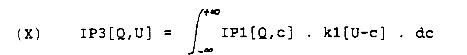
- l'image IP3[Q,U] est alors calculée à partir de la formule (X), qui représente la convolution de IP1, par cette fonction de filtrage k1[b], b correspondant au paramètre "de ligne" U;
- mais en notant b= n.u, où n est un entier relatif compris entre -N/2 et +N/2, N étant le nombre de capteurs, le Demandeur a observé que l'on peut exprimer k1[n.u] sous forme discrète, conformément à la formule (XI).
- cette technique est un renforcement de contours de l'image IP1 en l'image IP3 (en l'espèce, celui auquel il a été fait référence plus haut);
- k1 étant une dérivée, ce renforcement de contours se fonde sur un traitement "différentiel" des mesures. Comme également décrit plus haut, on pourrait faire ce traitement au niveau des capteurs.
- calculer l'image des projections aux contours renforcés IP3, à l'étape 262, comme il vient d'être dit,
- en déduire à l'étape 264 les images auxiliaires IP3x et IP3y, ce qui peut se faire également au fur et à mesure de l'arrivée des lignes,
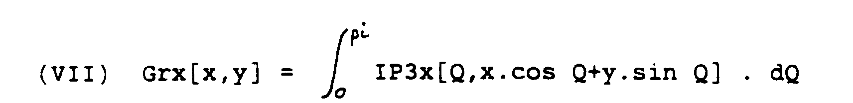
- calculer à l'étape 266 les images de composantes en x et en y de gradient dans l'espace réel, conformément aux formules (VII) et (VIII), ce traitement étant global en Q, qui varie de 0 à pi pour toutes les lignes, et
- en déduire une image de modules du vecteur gradient dans l'espace réel, IR[x,y], défini classiquement par la formule (XIII).


Claims (23)
- Dispositif d'aide à l'inspection d'un corps, du type comprenant:caractérisé en ce que les moyens de traitement (22) comprennent des moyens d'analyse différentielle des signaux de données brutes relativement à leurs paramètres d'axe, pour y déterminer des points critiques, où se manifeste un saut d'intensité du signal capté, de sorte que chacun de ces points correspond à une ligne d'acquisition tangente à une frontière interne ou externe du corps examiné, tandis que les paramètres d'axe des points critiques représentent dans leur ensemble la position d'une partie au moins desdites frontières du corps.des moyens (20) pour acquérir un ensemble rangé de signaux de données brutes, dont chacun représente l'intensité d'un faisceau d'ondes de type donné, qui sort du corps le long d'un axe dit "ligne d'acquisition", lequel axe est désigné par au moins deux paramètres, tandis que les données brutes définissent, en fonction de ces paramètres d'axe, une "image des projections" du rayonnement dans un "espace des projections", qui est un espace multi-dimensionnel, dual de l'espace réel, chaque point de l'espace des projections représentant une droite de l'espace réel, etdes moyens (22) de traitement de ces signaux de données brutes,
- Dispositif selon la revendication 1, caractérisé en ce qu'il comprend en outre:un emplacement pour recevoir un corps (B) à examiner, etun ensemble de capteurs (Ci) dont chacun est sensible à un faisceau d'ondes sortant du corps selon un trajet ou "ligne d'acquisition" qui lui est propre, cet ensemble de capteurs fournissant les données brutes.
- Dispositif selon la revendication 2, caractérisé en ce que les capteurs (Ci) sont disposés en agencement unidimensionnel, les paramètres d'axe comprenant une coordonnée de position et au moins une coordonnée de direction.
- Dispositif selon la revendication 2, caractérisé en ce que les capteurs (Ci) sont disposés en agencement bidimensionnel, les paramètres d'axe comprenant au moins deux coordonnées de position et au moins une coordonnée de direction.
- Dispositif selon l'une des revendications 3 et 4, caractérisé en ce que l'ensemble de capteurs (Ci) est mobile par rapport au corps, ce qui permet une variation, en fonction du temps, de l'un au moins des paramètres d'axe.
- Dispositif selon l'une des revendications précédentes, caractérisé en ce que les moyens d'analyse différentielle comportent:des moyens de scrutation pour déterminer l'ensemble des points critiques de l'image des projections où se manifeste un saut d'intensité du signal capté, etdes moyens de traitement d'image, pour déterminer ensuite des contours critiques, formés chacun d'une succession continue de points critiques.
- Dispositif selon l'une des revendications précédentes, caractérisé en ce que les signaux de données brutes sont exprimés sous forme différentielle.
- Dispositif selon l'une des revendications précédentes, caractérisé en ce qu'il lui est associé un appareil d'intervention sur le corps, commandé à partir des paramètres d'axe des points critiques.
- Dispositif selon l'une des revendications précédentes, caractérisé en ce que les moyens de traitement comportent en outre des moyens de conversion pour déterminer des signaux reconstruits, qui représentent, dans l'espace réel, la position d'une partie au moins desdites frontières.
- Procédé de traitement de signaux relatifs à l'inspection d'un corps à l'aide de faisceaux d'ondes qui en sortent, du type dans lequel:caractérisé en ce que le traitement comprend une analyse différentielle des signaux de données brutes, pour y déterminer des points critiques, où se manifeste un saut d'intensité du signal capté, de sorte que chacun de ces points correspond à une ligne d'acquisition tangente à une frontière interne ou externe du corps examiné, tandis que les paramètres d'axe des points critiques représentent dans leur ensemble la position d'une partie au moins desdites frontières du corps.on acquiert un ensemble rangé de signaux de données brutes, dont chacun représente l'intensité du faisceau d'ondes qui sort du corps le long d'un axe dit "ligne d'acquisition", lequel axe est désigné par au moins deux paramètres, tandis que les données brutes définissent, en fonction de ces paramètres d'axe, une "image des projections" du rayonnement dans un "espace des projections", qui est un espace multi-dimensionnel, dual de l'espace réel, chaque point de l'espace des projections représentant une droite de l'espace réel, eton traite ces signaux de données brutes, pour obtenir des informations spatiales sur ledit corps,
- Procédé selon la revendication 10, caractérisé en ce que l'analyse différentielle comporte:une scrutation pour déterminer l'ensemble des points critiques de l'image des projections où se manifeste un saut d'intensité du signal capté, etun traitement d'image, pour déterminer ensuite des contours critiques, formés chacun d'une succession continue de points critiques.
- Procédé selon l'une des revendications 10 et 11, caractérisé en ce que les signaux de données brutes sont exprimés sous forme différentielle.
- Procédé selon l'une des revendications 10 à 12, caractérisé en ce qu'il comprend en outre l'opération consistant à commander un positionnement à partir des paramètres d'axe des points critiques.
- Procédé selon l'une des revendications 10 à 13, caractérisé en ce qu'il comprend en outre une opération de conversion des paramètres d'axe des points critiques en signaux reconstruits représentant, dans l'espace réel, la position d'une partie au moins desdites frontières.
- Procédé selon la revendication 14, caractérisé en ce que ladite conversion comprend une rétroprojection pondérée des points critiques dans l'espace réel, et un suivi de contours dans cet espace réel, lequel fournit lesdites frontières.
- Procédé selon la revendication 14, caractérisé en ce que ladite conversion comprend une transformation géométrique locale.
- Procédé selon la revendication 14, caractérisé en ce que ladite conversion comprend une transformation géométrique globale.
- Procédé selon la revendication 14, caractérisé en ce que ladite conversion comprend une transformation algorithmique, opérant par:sélection de toutes les droites correspondant à des points d'un même contour critique,sélection de celles de ces droites qui appartiennent à un même plan courant,association à chacune de ces droites du demi-plan qu'elle délimite dans le plan courant, du côté défini par le gradient, etconstruction progressive de l'intersection de ces demi-plans, sous réserve d'obtenir une frontière localement convexe.
- Procédé selon la revendication 11, dans lequel on dispose d'une estimation des frontières internes et externe du corps dans l'espace réel, caractérisé en ce que ladite conversion comprend:la conversion de ces frontières estimées de l'espace réel en contours critiques estimés dans l'espace dual,la comparaison des contours critiques estimés aux contours critiques observés, ce qui fournit des informations de rectification,la conversion de ces informations de rectification, de l'espace dual dans l'espace réel, etla mise à jour de ladite estimation des frontières, ces opérations étant répétées jusqu'à atteindre un degré choisi de concordance entre les contours critiques estimés et les contours critiques observés, ce qui fournit les frontières reconstruites.
- Procédé selon la revendication 19, caractérisé en ce que les informations de rectification sont des corrections aux contours critiques estimés, que l'on convertit de l'espace dual dans l'espace réel, et à partir desquelles on met à jour ladite estimation des frontières.
- Procédé selon la revendication 19, caractérisé en ce que les informations de rectification sont des contours critiques estimés corrigés, que l'on convertit de l'espace dual dans l'espace réel, et à partir desquels on met à jour ladite estimation des frontières.
- Procédé selon l'une des revendications 19 à 21, appliqué au suivi dynamique du corps, chaque estimation initiale des frontières étant définie à partir d'au moins une frontière reconstruite antérieurement.
- Procédé selon la revendication 10, caractérisé en ce que la scrutation comprend le calcul d'une image des projections aux contours renforcés (IP3), et en ce que le traitement d'image comprend la rétroprojection de composantes (IP3x, IP3y) de cette image en images de composantes de gradient (Grx, Gry) dans l'espace réel, ce qui permet la synthèse d'une image de gradient dans l'espace réel (IR[x,y]).
Applications Claiming Priority (3)
| Application Number | Priority Date | Filing Date | Title |
|---|---|---|---|
| FR9105138A FR2675927B1 (fr) | 1991-04-25 | 1991-04-25 | Procede et dispositif d'aide a l'inspection d'un corps, notamment pour la tomographie. |
| FR9105138 | 1991-04-25 | ||
| PCT/FR1992/000252 WO1992020032A1 (fr) | 1991-04-25 | 1992-03-19 | Procede et dispositif d'aide a l'inspection d'un corps, notamment pour la tomographie |
Publications (2)
| Publication Number | Publication Date |
|---|---|
| EP0536357A1 EP0536357A1 (fr) | 1993-04-14 |
| EP0536357B1 true EP0536357B1 (fr) | 1998-07-22 |
Family
ID=9412268
Family Applications (1)
| Application Number | Title | Priority Date | Filing Date |
|---|---|---|---|
| EP92908376A Expired - Lifetime EP0536357B1 (fr) | 1991-04-25 | 1992-03-19 | Procede et dispositif d'aide a l'inspection d'un corps, notamment pour la tomographie |
Country Status (9)
| Country | Link |
|---|---|
| US (1) | US5421330A (fr) |
| EP (1) | EP0536357B1 (fr) |
| JP (1) | JPH05508093A (fr) |
| AT (1) | ATE168801T1 (fr) |
| DE (1) | DE69226321T2 (fr) |
| DK (1) | DK0536357T3 (fr) |
| ES (1) | ES2121851T3 (fr) |
| FR (1) | FR2675927B1 (fr) |
| WO (1) | WO1992020032A1 (fr) |
Families Citing this family (21)
| Publication number | Priority date | Publication date | Assignee | Title |
|---|---|---|---|---|
| GB9122843D0 (en) * | 1991-10-28 | 1991-12-11 | Imperial College | Method and apparatus for image processing |
| FR2736163B1 (fr) * | 1995-06-29 | 1997-08-22 | Sopha Medical | Methode d'obtention, en medecine nucleaire, d'une image du corps d'un patient corrigee des troncatures |
| WO1997005574A1 (fr) * | 1995-07-27 | 1997-02-13 | Imperial Cancer Research Technology Limited | Segmentation et analyse de donnees brutes utilisees en imagerie tomographique |
| US5682887A (en) * | 1996-03-20 | 1997-11-04 | Siemens Corporate Research, Inc. | Determining the position range of the heart from a sequence of projection images using 1-D pseudo motion analysis |
| US5699799A (en) * | 1996-03-26 | 1997-12-23 | Siemens Corporate Research, Inc. | Automatic determination of the curved axis of a 3-D tube-shaped object in image volume |
| US5908387A (en) * | 1996-06-21 | 1999-06-01 | Quinton Instrument Company | Device and method for improved quantitative coronary artery analysis |
| US5815591A (en) * | 1996-07-10 | 1998-09-29 | R2 Technology, Inc. | Method and apparatus for fast detection of spiculated lesions in digital mammograms |
| US6171243B1 (en) * | 1997-05-30 | 2001-01-09 | Picker International, Inc. | Combination of collimated and coincidence information for positron imaging |
| US6201888B1 (en) | 1998-02-18 | 2001-03-13 | International Business Machines Corporation | System and method for restoring, describing and graphically displaying noise-corrupted boundaries in tomography images |
| WO1999057683A1 (fr) | 1998-05-04 | 1999-11-11 | The Johns Hopkins University | Procede et appareil de segmentation de petites structures dans des images |
| IL127254A0 (en) * | 1998-11-25 | 1999-09-22 | Univ Ramot | Method and system for automatic classification and quantitative evaluation of adnexal masses bases on a cross-sectional or projectional images of the adnex |
| US6944322B2 (en) * | 2001-03-28 | 2005-09-13 | Visiongate, Inc. | Optical tomography of small objects using parallel ray illumination and post-specimen optical magnification |
| US20030171665A1 (en) * | 2002-03-05 | 2003-09-11 | Jiang Hsieh | Image space correction for multi-slice helical reconstruction |
| US20040120566A1 (en) * | 2002-12-19 | 2004-06-24 | Gines David L. | Compact storage of projection matrix for tomography using separable operators |
| US20080031400A1 (en) * | 2004-05-06 | 2008-02-07 | Luc Beaulieu | 3D Localization Of Objects From Tomography Data |
| US7139367B1 (en) * | 2004-09-29 | 2006-11-21 | Khai Minh Le | Time share digital integration method and apparatus for processing X-ray images |
| US6991738B1 (en) | 2004-10-13 | 2006-01-31 | University Of Washington | Flow-through drum centrifuge |
| US7176916B2 (en) * | 2005-04-15 | 2007-02-13 | T.I.E.S., Inc. | Object identifying system for segmenting unreconstructed data in image tomography |
| WO2009079644A2 (fr) * | 2007-12-18 | 2009-06-25 | Brijot Imaging Systems, Inc. | Méthodologie logicielle pour la détection autonome d'objet caché et l'évaluation de menace |
| US8224021B2 (en) * | 2008-03-14 | 2012-07-17 | Millivision Technologies, Inc. | Method and system for automatic detection of a class of objects |
| US11069054B2 (en) | 2015-12-30 | 2021-07-20 | Visiongate, Inc. | System and method for automated detection and monitoring of dysplasia and administration of immunotherapy and chemotherapy |
Family Cites Families (8)
| Publication number | Priority date | Publication date | Assignee | Title |
|---|---|---|---|---|
| GB1471531A (en) * | 1973-04-25 | 1977-04-27 | Emi Ltd | Radiography |
| US4038551A (en) * | 1973-04-25 | 1977-07-26 | E M I Limited | Circuit for signal data obtained from an axial tomographic scanning apparatus |
| US4114042A (en) * | 1973-04-25 | 1978-09-12 | Emi Limited | Radiography |
| US4233662A (en) * | 1973-04-25 | 1980-11-11 | Emi Limited | Radiography |
| US4873632A (en) * | 1984-04-27 | 1989-10-10 | The Curators Of The University Of Missouri | Apparatus and methods for scatter reduction in radiation imaging |
| US4903204A (en) * | 1987-12-01 | 1990-02-20 | Duke University | Matrix inversion tomosynthesis improvements in longitudinal X-ray slice imaging |
| US5032728A (en) * | 1988-11-09 | 1991-07-16 | The University Of Iowa Research Foundation | Single photon emission computed tomography system |
| US5170439A (en) * | 1991-06-11 | 1992-12-08 | Picker International, Inc. | Cone beam reconstruction using combined circle and line orbits |
-
1991
- 1991-04-25 FR FR9105138A patent/FR2675927B1/fr not_active Expired - Fee Related
-
1992
- 1992-03-19 AT AT92908376T patent/ATE168801T1/de not_active IP Right Cessation
- 1992-03-19 DE DE69226321T patent/DE69226321T2/de not_active Expired - Fee Related
- 1992-03-19 ES ES92908376T patent/ES2121851T3/es not_active Expired - Lifetime
- 1992-03-19 WO PCT/FR1992/000252 patent/WO1992020032A1/fr active IP Right Grant
- 1992-03-19 JP JP92507695A patent/JPH05508093A/ja active Pending
- 1992-03-19 DK DK92908376T patent/DK0536357T3/da active
- 1992-03-19 EP EP92908376A patent/EP0536357B1/fr not_active Expired - Lifetime
- 1992-03-19 US US07/960,419 patent/US5421330A/en not_active Expired - Lifetime
Also Published As
| Publication number | Publication date |
|---|---|
| ES2121851T3 (es) | 1998-12-16 |
| DE69226321T2 (de) | 1999-04-01 |
| US5421330A (en) | 1995-06-06 |
| EP0536357A1 (fr) | 1993-04-14 |
| JPH05508093A (ja) | 1993-11-18 |
| DE69226321D1 (de) | 1998-08-27 |
| DK0536357T3 (da) | 1999-02-01 |
| WO1992020032A1 (fr) | 1992-11-12 |
| FR2675927A1 (fr) | 1992-10-30 |
| ATE168801T1 (de) | 1998-08-15 |
| FR2675927B1 (fr) | 1993-07-30 |
Similar Documents
| Publication | Publication Date | Title |
|---|---|---|
| EP0536357B1 (fr) | Procede et dispositif d'aide a l'inspection d'un corps, notamment pour la tomographie | |
| JP6636845B2 (ja) | フォービエイテッド圧縮投影を用いたハイパースペクトルデミキシング | |
| JP5832523B2 (ja) | 光コヒーレンストモグラフィのための動き補正および画像改善の方法および装置 | |
| US20180017501A1 (en) | System and method for surface inspection | |
| JP6490219B2 (ja) | デジタルホログラフィにおけるオートフォーカスシステムおよびオートフォーカス方法 | |
| US20120170848A1 (en) | Artifact management in rotational imaging | |
| US20110150293A1 (en) | Methods, Systems and Computer Program Products for Biometric Identification by Tissue Imaging Using Optical Coherence Tomography (OCT) | |
| JP2016514996A (ja) | 較正及び画像処理装置、方法、並びにシステム | |
| US20160213253A1 (en) | Analysis of optical tomography (oct) images | |
| WO2016207423A1 (fr) | Reconstruction robuste pour tomographie par ordinateur en champ sombre et à contraste de phase | |
| AU2013260650B2 (en) | Rotational phase unwrapping | |
| Aldea et al. | Robust crack detection for unmanned aerial vehicles inspection in an a-contrario decision framework | |
| FR3086428A1 (fr) | Procede, programme d'ordinateur et systeme de detection et localisation d'objet dans une scene tridimensionnelle | |
| CA2687596A1 (fr) | Procede et dispositif d'acquisition et de traitement d'images pour la detection de lesions evolutives | |
| EP2961316B1 (fr) | Procede automatique de determination predictive de la position de la peau | |
| Paturkar et al. | 3D reconstruction of plants under outdoor conditions using image-based computer vision | |
| FR2773247A1 (fr) | Procede de traitement d'une image multidimensionnelle bruitee et appareil d'imagerie medicale mettant en oeuvre ce procede | |
| FR2936890A1 (fr) | Procede de traitement d'image pour estimer une deformation d'un cerveau d'un patient | |
| EP1190208B1 (fr) | Procede de mesurage d'un objet tridimensionnel, ou d'un ensemble d'objets | |
| WO2005001775A1 (fr) | Procede de reconstruction d'une image tomographique par une methode analytique comprenant une modelisation amelioree du mouvement de l'objet | |
| US20160071257A1 (en) | Apparatus and method for parameterizing a plant | |
| CA2685562A1 (fr) | Procede et dispositif d'acquisition et de traitement de donnees pour la detection de l'evolution dans le temps de lesions evolutives | |
| Harikumar | Effect of discontinuity adaptive MRF models with Noise classifier | |
| Dikici | Ultrasound cardiac modeling, segmentation and tracking | |
| FR2960813A1 (fr) | Dispositif robotise et procede associe |
Legal Events
| Date | Code | Title | Description |
|---|---|---|---|
| PUAI | Public reference made under article 153(3) epc to a published international application that has entered the european phase |
Free format text: ORIGINAL CODE: 0009012 |
|
| 17P | Request for examination filed |
Effective date: 19921217 |
|
| AK | Designated contracting states |
Kind code of ref document: A1 Designated state(s): AT BE CH DE DK ES FR GB GR IT LI LU MC NL SE |
|
| GRAG | Despatch of communication of intention to grant |
Free format text: ORIGINAL CODE: EPIDOS AGRA |
|
| 17Q | First examination report despatched |
Effective date: 19970926 |
|
| GRAG | Despatch of communication of intention to grant |
Free format text: ORIGINAL CODE: EPIDOS AGRA |
|
| GRAH | Despatch of communication of intention to grant a patent |
Free format text: ORIGINAL CODE: EPIDOS IGRA |
|
| GRAH | Despatch of communication of intention to grant a patent |
Free format text: ORIGINAL CODE: EPIDOS IGRA |
|
| GRAA | (expected) grant |
Free format text: ORIGINAL CODE: 0009210 |
|
| AK | Designated contracting states |
Kind code of ref document: B1 Designated state(s): AT BE CH DE DK ES FR GB GR IT LI LU MC NL SE |
|
| PG25 | Lapsed in a contracting state [announced via postgrant information from national office to epo] |
Ref country code: GR Free format text: LAPSE BECAUSE OF NON-PAYMENT OF DUE FEES Effective date: 19980722 |
|
| REF | Corresponds to: |
Ref document number: 168801 Country of ref document: AT Date of ref document: 19980815 Kind code of ref document: T |
|
| REG | Reference to a national code |
Ref country code: CH Ref legal event code: NV Representative=s name: KATZAROV S.A. Ref country code: CH Ref legal event code: EP |
|
| GBT | Gb: translation of ep patent filed (gb section 77(6)(a)/1977) |
Effective date: 19980724 |
|
| REF | Corresponds to: |
Ref document number: 69226321 Country of ref document: DE Date of ref document: 19980827 |
|
| REG | Reference to a national code |
Ref country code: ES Ref legal event code: FG2A Ref document number: 2121851 Country of ref document: ES Kind code of ref document: T3 |
|
| REG | Reference to a national code |
Ref country code: DK Ref legal event code: T3 |
|
| PG25 | Lapsed in a contracting state [announced via postgrant information from national office to epo] |
Ref country code: AT Free format text: LAPSE BECAUSE OF NON-PAYMENT OF DUE FEES Effective date: 19990319 |
|
| PG25 | Lapsed in a contracting state [announced via postgrant information from national office to epo] |
Ref country code: SE Free format text: LAPSE BECAUSE OF NON-PAYMENT OF DUE FEES Effective date: 19990320 Ref country code: ES Free format text: LAPSE BECAUSE OF NON-PAYMENT OF DUE FEES Effective date: 19990320 |
|
| PG25 | Lapsed in a contracting state [announced via postgrant information from national office to epo] |
Ref country code: LI Free format text: LAPSE BECAUSE OF NON-PAYMENT OF DUE FEES Effective date: 19990331 Ref country code: DK Free format text: LAPSE BECAUSE OF NON-PAYMENT OF DUE FEES Effective date: 19990331 Ref country code: CH Free format text: LAPSE BECAUSE OF NON-PAYMENT OF DUE FEES Effective date: 19990331 |
|
| PLBE | No opposition filed within time limit |
Free format text: ORIGINAL CODE: 0009261 |
|
| STAA | Information on the status of an ep patent application or granted ep patent |
Free format text: STATUS: NO OPPOSITION FILED WITHIN TIME LIMIT |
|
| 26N | No opposition filed | ||
| PG25 | Lapsed in a contracting state [announced via postgrant information from national office to epo] |
Ref country code: MC Free format text: LAPSE BECAUSE OF NON-PAYMENT OF DUE FEES Effective date: 19990930 |
|
| EUG | Se: european patent has lapsed |
Ref document number: 92908376.4 |
|
| REG | Reference to a national code |
Ref country code: CH Ref legal event code: PL |
|
| EUG | Se: european patent has lapsed |
Ref document number: 92908376.4 |
|
| REG | Reference to a national code |
Ref country code: DK Ref legal event code: EBP |
|
| PGFP | Annual fee paid to national office [announced via postgrant information from national office to epo] |
Ref country code: NL Payment date: 20000615 Year of fee payment: 9 |
|
| PGFP | Annual fee paid to national office [announced via postgrant information from national office to epo] |
Ref country code: LU Payment date: 20000629 Year of fee payment: 9 |
|
| PGFP | Annual fee paid to national office [announced via postgrant information from national office to epo] |
Ref country code: BE Payment date: 20000630 Year of fee payment: 9 |
|
| PG25 | Lapsed in a contracting state [announced via postgrant information from national office to epo] |
Ref country code: LU Free format text: LAPSE BECAUSE OF NON-PAYMENT OF DUE FEES Effective date: 20010319 |
|
| PGFP | Annual fee paid to national office [announced via postgrant information from national office to epo] |
Ref country code: DE Payment date: 20010330 Year of fee payment: 10 |
|
| PG25 | Lapsed in a contracting state [announced via postgrant information from national office to epo] |
Ref country code: BE Free format text: LAPSE BECAUSE OF NON-PAYMENT OF DUE FEES Effective date: 20010331 |
|
| BERE | Be: lapsed |
Owner name: INSTITUT NATIONAL DE RECHERCHE EN INFORMATIQUE ET Effective date: 20010331 |
|
| PG25 | Lapsed in a contracting state [announced via postgrant information from national office to epo] |
Ref country code: NL Free format text: LAPSE BECAUSE OF NON-PAYMENT OF DUE FEES Effective date: 20011001 |
|
| NLV4 | Nl: lapsed or anulled due to non-payment of the annual fee |
Effective date: 20011001 |
|
| REG | Reference to a national code |
Ref country code: GB Ref legal event code: IF02 |
|
| PG25 | Lapsed in a contracting state [announced via postgrant information from national office to epo] |
Ref country code: DE Free format text: LAPSE BECAUSE OF NON-PAYMENT OF DUE FEES Effective date: 20021001 |
|
| REG | Reference to a national code |
Ref country code: ES Ref legal event code: FD2A Effective date: 20000411 |
|
| PG25 | Lapsed in a contracting state [announced via postgrant information from national office to epo] |
Ref country code: IT Free format text: LAPSE BECAUSE OF NON-PAYMENT OF DUE FEES;WARNING: LAPSES OF ITALIAN PATENTS WITH EFFECTIVE DATE BEFORE 2007 MAY HAVE OCCURRED AT ANY TIME BEFORE 2007. THE CORRECT EFFECTIVE DATE MAY BE DIFFERENT FROM THE ONE RECORDED. Effective date: 20050319 |
|
| PGFP | Annual fee paid to national office [announced via postgrant information from national office to epo] |
Ref country code: GB Payment date: 20090318 Year of fee payment: 18 |
|
| PGFP | Annual fee paid to national office [announced via postgrant information from national office to epo] |
Ref country code: FR Payment date: 20090310 Year of fee payment: 18 |
|
| GBPC | Gb: european patent ceased through non-payment of renewal fee |
Effective date: 20100319 |
|
| REG | Reference to a national code |
Ref country code: FR Ref legal event code: ST Effective date: 20101130 |
|
| PG25 | Lapsed in a contracting state [announced via postgrant information from national office to epo] |
Ref country code: FR Free format text: LAPSE BECAUSE OF NON-PAYMENT OF DUE FEES Effective date: 20100331 |
|
| PG25 | Lapsed in a contracting state [announced via postgrant information from national office to epo] |
Ref country code: GB Free format text: LAPSE BECAUSE OF NON-PAYMENT OF DUE FEES Effective date: 20100319 |