EP0536025B1 - Frequenzkorrelator - Google Patents
Frequenzkorrelator Download PDFInfo
- Publication number
- EP0536025B1 EP0536025B1 EP92402633A EP92402633A EP0536025B1 EP 0536025 B1 EP0536025 B1 EP 0536025B1 EP 92402633 A EP92402633 A EP 92402633A EP 92402633 A EP92402633 A EP 92402633A EP 0536025 B1 EP0536025 B1 EP 0536025B1
- Authority
- EP
- European Patent Office
- Prior art keywords
- correlated
- signals
- light
- fiber
- light source
- Prior art date
- Legal status (The legal status is an assumption and is not a legal conclusion. Google has not performed a legal analysis and makes no representation as to the accuracy of the status listed.)
- Expired - Lifetime
Links
Images

Classifications
-
- G—PHYSICS
- G06—COMPUTING OR CALCULATING; COUNTING
- G06E—OPTICAL COMPUTING DEVICES
- G06E3/00—Devices not provided for in group G06E1/00, e.g. for processing analogue or hybrid data
- G06E3/001—Analogue devices in which mathematical operations are carried out with the aid of optical or electro-optical elements
- G06E3/005—Analogue devices in which mathematical operations are carried out with the aid of optical or electro-optical elements using electro-optical or opto-electronic means
Definitions
- the invention relates to a frequency correlator and more particularly to a correlator of electrical signals.
- the invention is particularly applicable to an information processing device ensuring the correlation of very broadband signals - typically 1 to 20 GHz.
- This device which exploits the non-linear optical properties of single-mode optical fibers (Kerr effect) is particularly well suited to the processing of signals having a large instantaneous bandwidth.
- This invention is based on a spatial integration of the optical nonlinearities induced in a single mode fiber. It can be extended to the production of broadband programmable filters.
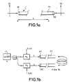
- FIGS. 1a and 1b show diagrams of the correlation device which is the subject of the invention.
- This device uses a single-mode fiber F1 having a third order optical non-linearity. That is to say a fiber in which a variation of photoinduced index is proportional to the intensity of the optical field in the core of the fiber.
- the fiber F1 receives, by its two ends A1, A2, two optical waves whose incident optical fields are perpendicular to the axis of the fiber F1.
- FIG. 1b two signals to be correlated S 1 (t) and S 2 (t) are transposed on an optical beam of frequency ⁇ o by means of broadband light intensity modulators M 1 and M 2 .
- These modulators can be made in integrated optics according to known techniques.
- the modulated beams E1 and E2 are transmitted to the ends A1 and A2 respectively of the fiber.
- the fiber is therefore the seat of variations in photoinduced indices by the interference of the modulated optical signals. These variations in indices are illustrated in FIG. 2 where ⁇ n (t, z) represents the amplitude of the photoinduced network and ⁇ represents the spatial period of the network of photoinduced index.
- the signals S 1 (t) and S 2 (t) to be correlated are electrical signals and the modulators M 1 , M 2 are electrooptical modulators.
- FIG. 3 represents the optical fiber F1 in which an array of indices has been registered by the interference of the modulated optical fields transmitted to the inputs A1 and A2.
- a reading optical beam (E L ) is transmitted to an input A1 of the fiber M. This transmission can be done using a semi-reflecting mirror MS. The optical beam is partly reflected by the photoinduced index grating. The reflected flux E d is returned by the mirror MS to a photodetector P.
- the reading beam E L has the same wavelength ⁇ as the modulated beams E 1 and E 2 . Its intensity I o is proportional to E 2 o .
- Each elementary portion of fiber of length dz (taken equal to c / ⁇ f RF where f RF is the maximum frequency of the microwave signals) at the abscissa z, leads, at each instant t, to a reflection coefficient R determined in amplitude of the probe wave E o .
- the intensity of the backscattered probe, and therefore the current of the photodetector, is directly proportional to the correlation product of the two signals S 1 and S 2 .
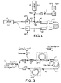
- FIG. 4 represents a detailed embodiment of the device of the invention.
- This device comprises a light source L1 (laser) emitting a beam of coherent light of wavelength ⁇ .
- This beam is transmitted to two electrooptical modulators M1, M2 which modulate the light received from the source L1, using electrical signals S 1 (t) and S 2 (t) to be correlated.
- the modulated beams E1 and E2 are transmitted to the ends A1 and A2 of the fiber F1.
- the two beams E1 and E2 interfere in the fiber F1 and give rise to the creation of one or more index networks in the fiber F1.
- a second light source L2 emits a light beam of the same wavelength ⁇ but of short coherence length corresponding to the inverse of the maximum frequency to be correlated.
- This beam is transmitted by two semi-reflecting mirrors MS1 and MS2 to the input A1 of the fiber. It is reflected by the photoinduced index networks.
- the reflected beam (s) are retransmitted by the mirrors MS1 and MS2 to a detector P of light intensity which thus identifies the correlation peaks.
- a time clock HT is put into service at the instant of application of the signals S 1 (t) and S 2 (t) to be correlated.
- the detector P informs a processing circuit which records the position of the time clock. The system can thus know the position of each detected correlation peak with respect to the start of the signals S 1 (t) and S 2 (t), that is to say the position of each peak of correlation within the signals S 1 (t) and S 2 (t).
- the modulators allow very wide band modulation (from 1 to 20 GHz for example) and can be produced in integrated optics.
- Such a system makes it possible to store pulses of duration 5 ⁇ s on a fiber of 1 km which makes it possible to correlate signals of duration 5 ⁇ s.
- signals of duration 5 ⁇ s According to another example, on 5 meters of fiber we can correlate pulses of 25 ns.
- FIG. 5 represents a broadband correlator with amplification of the optical signals transmitted to the fiber F1.
- the device of FIG. 5 comprises elements which complete the invention.
- An isolator I1 prevents any return of light to the source L1.
- the transmission of the beam emitted by the source L1 to the modulators M1 and M2 is done by a coupler C1 achievable in integrated optics.
- the beams modulated by the modulators M1 and M2 are amplified by fiber amplifiers AF1 and AF2.
- these amplifiers each include an Erbium doped fiber.
- the read laser L2 is coupled, to the optical path of the beam modulated by the modulator M1, between the modulator M1 and the amplifier AF1 so that the read beam benefits from the amplification by the amplifier AF1.
- This coupling is done by an isolator I2 and a coupler C2 (in optics integrated for example).
- the detector P is coupled to the access A1 of the fiber F1 by a coupler C3 (achievable in integrated optics). Although this is not shown, an amplifier can also be provided between the detector P and the coupler C3.
- This device allows modulation at low levels, then to adjust the optical intensity to the level necessary to generate a sufficient index variation by the Kerr effect.
- Amplification gains of 20 to 30 dB for 30 meters of fiber are achievable in fiber amplifiers, for example Erbium doped, at 1.55 ⁇ m.
- the device of the invention allows a very compact embodiment using integrated optical techniques.
- the amplifiers can be made as a semiconductor amplifier.
- the device of the invention can also be applied to a programmable filter.
- This reflectivity over a fiber length of 5 m makes it possible to use a probe laser with a coherence length of 5 mm to 1.32 ⁇ m of a few tens of mW.
Landscapes
- Physics & Mathematics (AREA)
- Engineering & Computer Science (AREA)
- Theoretical Computer Science (AREA)
- Mathematical Physics (AREA)
- Nonlinear Science (AREA)
- Optics & Photonics (AREA)
- General Physics & Mathematics (AREA)
- Optical Communication System (AREA)
Claims (6)
- Frequenzkorrelator, dadurch gekennzeichnet, daß er enthält:- eine Monomoden-Lichtleitfaser (F1), die eine optische Nichtlinearität der dritten Ordnung aufweist und ein erstes Ende (A1) und ein zweites Ende (A2) besitzt;- wenigstens eine erste Lichtquelle (L1), die eine kohärente erste Lichtwelle aussendet;- einen ersten Lichtmodulator (M1), der einen Teil der ersten Lichtwelle empfängt, diesen unter der Steuerung eines ersten zu korrelierenden Steuersignals (S1t) moduliert und diese erste modulierte Welle zum ersten Ende der Lichtleitfaser überträgt;- einen zweiten Lichtmodulator (M2), der einen anderen Teil der ersten Lichtwelle empfängt, diesen unter der Steuerung eines zweiten zu korrelierenden Steuersignals (S2t) moduliert und diese zweite modulierte Welle zum zweiten Ende der Lichtleitfaser überträgt;- eine zweite Lichtquelle (L2), die ein Leselichtbündel in die Lichtleitfaser durch das eine der Enden,
beispielsweise das erste Ende (A1), sendet;- einen Intensitäts-Detektor (P), der an das gleiche Ende der Faser wie die zweite Lichtquelle, gemäß dem gewählten Beispiel das erste Ende (A1), angekoppelt ist. - Korrelator nach Anspruch 1, dadurch gekennzeichnet, daß die zweite Lichtquelle (L2) eine Kohärenzbreite aufweist, die im wesentlichen gleich dem Kehrwert des maximalen Wertes der Frequenzen der zu korrelierenden Signale ist.
- Korrelator nach Anspruch 1, dadurch gekennzeichnet, daß die von der ersten Lichtquelle (L1) ausgesendete erste Lichtwelle eine Wellenlänge hat, die im wesentlichen gleich derjenigen des von der zweiten Lichtquelle (L2) ausgesendeten Leselichtbündels ist.
- Korrelator nach Anspruch 1, dadurch gekennzeichnet, daß er einen Taktgeber (HT) enthält, der die Zeitpunkte des Empfangs der zu korrelierenden Signale (S1t und S2t) durch die Modulatoren (M1, M2) erfaßt und die Zeitpunkte der Erfassung jeder Korrelationsspitze durch den Detektor (P) angibt.
- Korrelator nach Anspruch 4, dadurch gekennzeichnet, daß er eine Verarbeitungsschaltung (CT) enthält, die vom Taktgeber (HT) die Empfangszeiten der zu korrelierenden Signale (S1t und S2t) und vom Detektor (P) die Erfassungszeit jeder Korrelationsspitze empfängt und dadurch die zeitliche Lage jeder Korrelationsspitze in jedem zu korrelierenden Signal berechnet.
- Korrelator nach Anspruch 1, dadurch gekennzeichnet, daß die zu korrelierenden Signale (S1t, S2t) elektrische Signale sind und daß die Modulatoren (M1, M2) elektrooptische Modulatoren sind.
Applications Claiming Priority (2)
| Application Number | Priority Date | Filing Date | Title |
|---|---|---|---|
| FR9112040 | 1991-10-01 | ||
| FR9112040A FR2681953B1 (fr) | 1991-10-01 | 1991-10-01 | Correlateur de frequences. |
Publications (2)
| Publication Number | Publication Date |
|---|---|
| EP0536025A1 EP0536025A1 (de) | 1993-04-07 |
| EP0536025B1 true EP0536025B1 (de) | 1996-08-28 |
Family
ID=9417454
Family Applications (1)
| Application Number | Title | Priority Date | Filing Date |
|---|---|---|---|
| EP92402633A Expired - Lifetime EP0536025B1 (de) | 1991-10-01 | 1992-09-25 | Frequenzkorrelator |
Country Status (4)
| Country | Link |
|---|---|
| US (1) | US5298740A (de) |
| EP (1) | EP0536025B1 (de) |
| DE (1) | DE69213148T2 (de) |
| FR (1) | FR2681953B1 (de) |
Families Citing this family (12)
| Publication number | Priority date | Publication date | Assignee | Title |
|---|---|---|---|---|
| US5936484A (en) * | 1995-02-24 | 1999-08-10 | Thomson-Csf | UHF phase shifter and application to an array antenna |
| FR2732783B1 (fr) * | 1995-04-07 | 1997-05-16 | Thomson Csf | Dispositif compact de retroprojection |
| FR2755516B1 (fr) | 1996-11-05 | 1999-01-22 | Thomson Csf | Dispositif compact d'illumination |
| DE19722370A1 (de) | 1997-05-28 | 1998-12-03 | Alsthom Cge Alcatel | Empfänger für ein optisches Nachrichtenübertragungssystem und Verfahren zu dessen Betrieb |
| FR2769154B1 (fr) * | 1997-09-30 | 1999-12-03 | Thomson Csf | Dispositif de synchronisation precise |
| FR2779579B1 (fr) | 1998-06-09 | 2000-08-25 | Thomson Csf | Dispositif de commande optique pour l'emission et la reception d'un radar large bande |
| FR2819061B1 (fr) * | 2000-12-28 | 2003-04-11 | Thomson Csf | Dispositif de controle de polarisation dans une liaison optique |
| FR2860291B1 (fr) * | 2003-09-26 | 2005-11-18 | Thales Sa | Dispositif capteur de vitesse de rotation interferometrique a fibre optique |
| FR2880204B1 (fr) * | 2004-12-23 | 2007-02-09 | Thales Sa | Source laser a recombinaison coherente de faisceaux |
| FR2945348B1 (fr) | 2009-05-07 | 2011-05-13 | Thales Sa | Procede d'identification d'une scene a partir d'images polarisees multi longueurs d'onde |
| CN112187347B (zh) * | 2020-09-18 | 2022-06-03 | 常州大学 | 一种用于测量光纤长度的装置和方法 |
| CN112187345B (zh) * | 2020-09-18 | 2021-07-27 | 常州大学 | 一种测量光纤长度的装置和方法 |
Family Cites Families (1)
| Publication number | Priority date | Publication date | Assignee | Title |
|---|---|---|---|---|
| FR2618278B1 (fr) * | 1987-07-17 | 1989-12-01 | Thomson Csf | Correlateur a fibre optique. |
-
1991
- 1991-10-01 FR FR9112040A patent/FR2681953B1/fr not_active Expired - Fee Related
-
1992
- 1992-09-25 DE DE69213148T patent/DE69213148T2/de not_active Expired - Fee Related
- 1992-09-25 EP EP92402633A patent/EP0536025B1/de not_active Expired - Lifetime
- 1992-09-30 US US07/953,852 patent/US5298740A/en not_active Expired - Fee Related
Also Published As
| Publication number | Publication date |
|---|---|
| DE69213148T2 (de) | 1997-01-23 |
| US5298740A (en) | 1994-03-29 |
| EP0536025A1 (de) | 1993-04-07 |
| DE69213148D1 (de) | 1996-10-02 |
| FR2681953B1 (fr) | 1993-11-05 |
| FR2681953A1 (fr) | 1993-04-02 |
Similar Documents
| Publication | Publication Date | Title |
|---|---|---|
| Lowery | New dynamic semiconductor laser model based on the transmission-line modelling method | |
| EP0536025B1 (de) | Frequenzkorrelator | |
| US6616353B1 (en) | Laser intensity noise suppression using unbalanced interferometer modulation | |
| AU617556B2 (en) | Interferometer | |
| EP0907073A1 (de) | Messanordnung zur Messung von verteilten optischen Fasersensoren mittels BOTDR | |
| US5479291A (en) | Non-linear optical interferometer with saturated amplifier | |
| US7557930B2 (en) | Bessel beam interferometer and measurement method | |
| CA1108431A (fr) | Echometre pour la localisation de defauts affectant les conducteurs de lumiere | |
| Bashan et al. | A forward Brillouin fibre laser | |
| Sayed et al. | Spectral width reduction using apodized cascaded fiber Bragg grating for post-dispersion compensation in WDM optical networks | |
| EP0603036A1 (de) | Optische Verarbeitungsvorrichtung für elektrische Signale | |
| CN112698355A (zh) | 一种基于电光调制技术的多波长相干激光雷达 | |
| EP0071309B1 (de) | Einrichtung zur Kopplung eines Senders und eines Strahlungsempfängers an ein Ende eines Lichtwellenleiters | |
| WO1993003406A1 (en) | Sagnac loop gates | |
| Kee et al. | Technique for measuring distributed temperature with 35cm spatial resolution utilising the Landau-Placzek ratio | |
| Jeon et al. | Optical fiber chromatic dispersion measurement using bidirectional modulation of an optical intensity modulator | |
| Set et al. | Rapid amplitude and group-delay measurement system based on intra-cavity-modulated swept-lasers | |
| JP3250587B2 (ja) | 波長分散測定装置 | |
| Cowle et al. | Optical fiber sources, amplifiers, and special fibers for application in multiplexed and distributed sensor systems | |
| Piasecki | Subpicosecond measurement of response of optical fibres | |
| Morsali et al. | Significance of high extinction ratio laser pulse generation in coherent optical time domain reflectometry | |
| JPH08334436A (ja) | 光ファイバの波長分散測定方法 | |
| EP4425726A1 (de) | Laservorrichtung und verfahren zur steuerung der linienbreite eines emittierten laserstrahls | |
| Batagelj et al. | Comparative study of interferometric and noninterferometric measurement schemes for fiber nonlinear coefficient measurement | |
| Hunsperger | Applications of Integrated Optics and Current Trends |
Legal Events
| Date | Code | Title | Description |
|---|---|---|---|
| PUAI | Public reference made under article 153(3) epc to a published international application that has entered the european phase |
Free format text: ORIGINAL CODE: 0009012 |
|
| AK | Designated contracting states |
Kind code of ref document: A1 Designated state(s): DE FR GB |
|
| 17P | Request for examination filed |
Effective date: 19930720 |
|
| RAP1 | Party data changed (applicant data changed or rights of an application transferred) |
Owner name: THOMSON-CSF |
|
| 17Q | First examination report despatched |
Effective date: 19950405 |
|
| GRAG | Despatch of communication of intention to grant |
Free format text: ORIGINAL CODE: EPIDOS AGRA |
|
| GRAH | Despatch of communication of intention to grant a patent |
Free format text: ORIGINAL CODE: EPIDOS IGRA |
|
| GRAH | Despatch of communication of intention to grant a patent |
Free format text: ORIGINAL CODE: EPIDOS IGRA |
|
| GRAA | (expected) grant |
Free format text: ORIGINAL CODE: 0009210 |
|
| AK | Designated contracting states |
Kind code of ref document: B1 Designated state(s): DE FR GB |
|
| REF | Corresponds to: |
Ref document number: 69213148 Country of ref document: DE Date of ref document: 19961002 |
|
| GBT | Gb: translation of ep patent filed (gb section 77(6)(a)/1977) |
Effective date: 19960919 |
|
| PLBE | No opposition filed within time limit |
Free format text: ORIGINAL CODE: 0009261 |
|
| STAA | Information on the status of an ep patent application or granted ep patent |
Free format text: STATUS: NO OPPOSITION FILED WITHIN TIME LIMIT |
|
| 26N | No opposition filed | ||
| REG | Reference to a national code |
Ref country code: GB Ref legal event code: IF02 |
|
| REG | Reference to a national code |
Ref country code: FR Ref legal event code: CD |
|
| PGFP | Annual fee paid to national office [announced via postgrant information from national office to epo] |
Ref country code: FR Payment date: 20030909 Year of fee payment: 12 |
|
| PGFP | Annual fee paid to national office [announced via postgrant information from national office to epo] |
Ref country code: GB Payment date: 20030924 Year of fee payment: 12 |
|
| PGFP | Annual fee paid to national office [announced via postgrant information from national office to epo] |
Ref country code: DE Payment date: 20031002 Year of fee payment: 12 |
|
| PG25 | Lapsed in a contracting state [announced via postgrant information from national office to epo] |
Ref country code: GB Free format text: LAPSE BECAUSE OF NON-PAYMENT OF DUE FEES Effective date: 20040925 |
|
| PG25 | Lapsed in a contracting state [announced via postgrant information from national office to epo] |
Ref country code: DE Free format text: LAPSE BECAUSE OF NON-PAYMENT OF DUE FEES Effective date: 20050401 |
|
| GBPC | Gb: european patent ceased through non-payment of renewal fee |
Effective date: 20040925 |
|
| PG25 | Lapsed in a contracting state [announced via postgrant information from national office to epo] |
Ref country code: FR Free format text: LAPSE BECAUSE OF NON-PAYMENT OF DUE FEES Effective date: 20050531 |
|
| REG | Reference to a national code |
Ref country code: FR Ref legal event code: ST |
|
| REG | Reference to a national code |
Ref country code: FR Ref legal event code: CL Ref country code: FR Ref legal event code: AU |