EP0535590A2 - Two-way repeater employing optical amplification - Google Patents
Two-way repeater employing optical amplification Download PDFInfo
- Publication number
- EP0535590A2 EP0535590A2 EP92116636A EP92116636A EP0535590A2 EP 0535590 A2 EP0535590 A2 EP 0535590A2 EP 92116636 A EP92116636 A EP 92116636A EP 92116636 A EP92116636 A EP 92116636A EP 0535590 A2 EP0535590 A2 EP 0535590A2
- Authority
- EP
- European Patent Office
- Prior art keywords
- optical
- optical signal
- output terminal
- port
- signal input
- Prior art date
- Legal status (The legal status is an assumption and is not a legal conclusion. Google has not performed a legal analysis and makes no representation as to the accuracy of the status listed.)
- Granted
Links
Images


Classifications
-
- H—ELECTRICITY
- H04—ELECTRIC COMMUNICATION TECHNIQUE
- H04B—TRANSMISSION
- H04B10/00—Transmission systems employing electromagnetic waves other than radio-waves, e.g. infrared, visible or ultraviolet light, or employing corpuscular radiation, e.g. quantum communication
- H04B10/29—Repeaters
- H04B10/291—Repeaters in which processing or amplification is carried out without conversion of the main signal from optical form
- H04B10/297—Bidirectional amplification
- H04B10/2972—Each direction being amplified separately
-
- H—ELECTRICITY
- H04—ELECTRIC COMMUNICATION TECHNIQUE
- H04B—TRANSMISSION
- H04B10/00—Transmission systems employing electromagnetic waves other than radio-waves, e.g. infrared, visible or ultraviolet light, or employing corpuscular radiation, e.g. quantum communication
- H04B10/29—Repeaters
- H04B10/291—Repeaters in which processing or amplification is carried out without conversion of the main signal from optical form
- H04B10/2912—Repeaters in which processing or amplification is carried out without conversion of the main signal from optical form characterised by the medium used for amplification or processing
Definitions
- the present invention relates to a two-way repeater for use in optical fiber communication systems, and more particularly to a two-way repeater including a laser medium by directly amplifying two optical signals, transmitted in mutually reverse directions over one optical fiber or one semiconductor laser, by optically exciting the fiber or the laser.
- This two-way repeater amplifies outward optical signals of 1.52 to 1.56 microns in wavelength transmitted from a first input/output terminal to a second input/output terminal (in the outward direction) with a laser-active optical fiber obtained by doping a quartz-based optical fiber with rare earth elements, such as erbium and neodymium, and amplifies inward optical signals of said wavelength transmitted in the inward direction with an optical fiber doped with the same rare earth elements.
- rare earth elements such as erbium and neodymium
- This two-way repeater includes two optical circulators for separating said inward and outward optical signals and a plurality of optical filters for cutting off pumping light and Amplified Spontaneous Emission (ASE) in addition to one or more of said active optical fiber.
- Said optical fiber here is exited by pumping light of 1.45 to 1.50 microns in wavelength. Details of the configuration and operation of this two-way repeater will be given in later paragraphs.
- said optical filters which much reflects optical signals are connected to the amplification output end of said active optical fiber, and there occurs multiple reflection of said first and second optical signals between said optical filters and other constituent elements including said rare earth-doped optical fiber.
- said two-way repeater since it simultaneously amplifies said first and second optical signals (inward and outward optical signals) with the same active optical fiber, it is difficult to separately control the degrees of amplification and outputs of said first and second optical signals in accordance with the specific requirements of a given optical fiber communication system and accordingly to produce a flexible optical fiber communication system.
- a first object of the present invention is to provide an optical amplifier based two-way repeater apparatus capable of achieving direct amplification of optical signals by the optical excitation of a laser-active optical fiber or the excitation of a semiconductor laser without inviting signal deterioration by oscillation or multiple reflection.
- a second object of the invention is to provide an optical amplifier based two-way repeater apparatus capable of controlling such optical amplification parameters as the degree of amplification and saturation output separately for inward and outward optical signals.
- An optical amplifier based two-way apparatus supplies a first optical signal from a first signal input/output terminal (an outward optical signal) to a second port of a first optical circulator, and amplifies said first optical signal generating at a third port of this optical circulator with a first optical amplifying medium.
- This amplified first optical signal is supplied to a first port of a second optical circulator, and further generates at a second signal input/output terminal connected to a second port of this second optical cirdulator to become the outward output optical signal of this two-way repeator apparatus.
- a second optical signal from sad second signal input/output terminal (an inward optical signal) is supplied to the second port of said second optical circulator, and said second optical signal generating at a third port of this second optical circulator is amplified by a second optical amplifying medium.
- This amplified second optical signal is supplied to a first port of said first optical circulator, and further generates at said second signal input/output terminal connected to the second port of this first optical circulator to become the inward output optical signal of this two-way repeater apparatus.
- Said first and second optical amplifying media are composed either of active optical fibers, prepared by doping optical fibers with a rare earth element such as erbium, or of semiconductor laser amplifiers. Where these optical amplifying media are active optical fibers, a pumping light is supplied by optical means to said active optical fibers. Or, where said optical amplifying media are semiconductor laser amplifiers, an current is supplied to the semiconductor laser elements which are the optical amplifying elements of these amplifiers.
- this two-way repeater using optical amplification is disclosed in the above cited Japanese Patent Publication Gazette.
- This two-way repeater amplifies an outward input optical signal S61, received at an input/output terminal 61, with active optical fibers 63 and 73, and generates an outward output optical signal S72, after the amplification of the optical signal S61, at another input/output terminal 75.
- an inward input optical signal S61r received at the input/output terminal 75, is amplified by the active optical fibers 73 and 63, and an inward output optical signal S72r, after the amplification of the optical signal S61r, is generated at the input/output terminal 61.
- suffix r indicates the inward direction of the optical signal.
- the outward input optical signal S61 is supplied to the active optical fiber 63 via an optical filter 62; and the optical fiber 63 amplifies the optical signal S61 into an optical signal S63.
- the optical fiber 63 here is excited by a pumping light S64 supplied from a pumping light source 66 via an optical multiplexer 67 and a four-port optical circulator 64, and inversively distributed.
- the optical signal S63 is supplied to a port 64b of the optical circulator 64, emerges at its port 64c (an optical signal S66), and is further supplied to an optical filter 69.
- the optical filter 69 cuts off the pumping light S64, which is reflected by the optical filter 62 and proceeds backward along the active optical fiber 63, and an ASE generating in the optical fiber along with the excitation by the pumping light S64, extracts from the optical signal S66 an optical signal S67, which is an amplified component of the outward optical signal S62, and causes it to emerge at the output end.
- the optical signal S67 and a pumping light S68 from a pumping light source 71 are multiplexed by an optical multiplexer 70, and a multiplexed optical signal S69 is supplied to the active optical fiber 73 via ports 72a and 72b of a four-port optical circulator 72 (an optical signal S70).
- the active optical fiber 73 is excited by the pumping light S68 component of the optical signal S70, and generates an optical signal S71 by amplifying its optical signal S67 component.
- the optical signal S71 undergoes a cut-off by an optical filter 74 of the pumping light S68 component and or an ASE generating in the active optical fiber 73 along with the excitation by the exciting light S68 component, and an optical signal S72, resulting from the extraction of an amplified component of the optical signal S67 from the optical signal 71, generates at the input/output terminal 75.
- the operation to amplify an inward optical signal is no different from that to amplify an outward optical signal.
- the optical signal S61r received at the input/output terminal 75 is amplified by the active optical fiber 73 via the optical filter 74 (an optical signal S63r).
- This amplified optical signal S63r passes the ports 72b and 72c of the optical circulator 72 and an optical filter 68 (an optical signal S67r).
- the optical signal S67r and the pumping light S64 from the pumping light source 66 are multiplexed by the optical multiplexer 67.
- the resultant multiplexed optical signal S69r is supplied to the active optical fiber 63 via the ports 64a and 64b of the optical circulator 64 (an optical signal S70r).
- the active optical fiber 63 is excited by the pumping light S64 component of the optical signal S70r, and amplifies the optical signal S67r component to generate an optical signal S71r.
- the optical signal S71r is supplied to the optical filter 62, which cuts off the pumping light S64 component and an ASE generating in the active optical fiber 63 along with the excitation by the pumping light component S64, extracts from the optical signal S71r an optical signal S72r, which results from the amplification of the optical signal S67r component, and causes it to emerge at the input/output terminal 61.
- the optical filters 62 and 74 which usually are narrow-band filters consisting of dielectric multi-layer films, let the optical signals S72 and S72r pass but cut off the pumping light S64 and S68 components out of the optical signals S7 and S71r, respectively, and have relatively high reflectances at the wavelengths of the optical signals S72 (and S62) and S71r (and S62r) as well. Therefore, if these optical filters 62 and 74 are directly connected to the amplification input or output ends of the active optical fibers 63 and 73, the optical signals S71 and S71r and the pumping lights S64 and S68 undergo high multiple reflection at these connection points. This multiple reflection subjects the optical signals S71 and S71r to oscillation and substantial distortion, and thereby obstructs the normal transmission of optical signals by this two-way repeater.
- optical circulators 64 and 74 are four-terminal circulators, and their respective fourth ports 64d and 72d are terminated by optical terminators 65 and 71, respectively. Their constituent elements are optically connected to one another either directly or via optical fibers.
- this two-way repeater simultaneously amplifies the optical signals S62 and S70r, transmitted in mutually opposite directions, with the same active optical fiber 63, and the optical signals S62r and S70 with the active optical fiber 73. Therefore it is difficult to separately control the degress of amplification and the output levels of the inward and outward optical signals, which are simultaneously amplified, in accordance with the requirements of the optical fiber communication system.
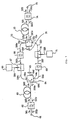
- an optical amplifier based two-way repeater 101 receives an outward input optical signal S1 of 1.552 microns in wavelength at an input/output terminal 1, amplifies an optical signal S7 deriving from said optical signal S1 with an optical fiber 11 doped with erbium (Er) ions, and causes an optical signal S13 deriving from this amplified optical signal S8 to generate at another input/output terminal 20.
- an optical signal S1 of 1.552 microns in wavelength at an input/output terminal 1
- this two-way repeater receives an inward optical signal S1r of 1.536 microns in wavelength at the input/output terminal 20, amplifies an optical signal S7r deriving From said optical signal S1r with the optical fiber 10 doped with Er ions, and causes an optical signal S13r deriving from this amplified optical signal S8r to generate at the input/output terminal 1.
- suffix r indicates the inward direction of the optical signals.
- this two-way repeater 101 receives the outward optical signal S1 at the input/output terminal 1, and supplies it to an optical branching circuit 3 including an optical directional coupler.
- the optical branching circuit 3 branches out an optical signal S2, which is a part of the optical signal S1, to an optical power monitor 2 including an optical detecting element such as a photodiode, and supplies an optical signal S3, which comprises the predominant remaining part of the optical signal S1, to an optical filter 5 consisting of a dielectric multi-layer film or the like.
- the optical power monitor 2 converts the optical signal S2 into an electric signal to monitor the state of the outward input optical signal S1, which is supplied to this two-way repeater 101, such as the level of the optical signal S1. Since the optical filters 5 transmits lights of the 1.55-micron band including wavelengths of 1.536 and 1.552 microns and cuts off lights of the 1.48-micron wavelength band, the optical signal S3 passes the optical filter 5 to be supplied to an optical multiplexer 6 (an optical signal S4).
- This optical signal S4 and a pumping light S5 of 1.48 microns in wavelength, generated from a pumping light source 7 including a laser oscillator, are multiplexed by the optical multiplexer 6.
- the resultant multiplexed optical signal S6 is supplied to a port 8b Of a four-port optical circulator 8, and emerges at its port 8c (an optical signal S7).
- the pumping light S5 component excites the electronic state of the Er ion-doped optical fiber 11 into inversive distribution, and the optical fiber 11 amplifies the optical signal S4 component in this excited state.
- An amplified optical signal S8 from the Er ion-doped optical fiber 11 is supplied to a port 13a of a four-port optical circulator 13, and emerges at its port 3b (an optical signal S9).
- the optical signal S9 passes an optical multiplexer 14, and is supplied to an optical filter 16 (an optical signal S10).
- the optical multiplexer 14 multiplexes the inward optical signal S10, to be described in further detail below, and a pumping light S5r of 1.48 microns in wavelength, which excites an Er ion-doped optical fiber 10.
- the optical filter 16 cuts off the pumping light S5 in the optical signal S10 and an ASE generating in the Er ion-doped optical fiber 11, extracts an optical signal S11 resulting from the amplification of the optical signal S4 component, and causes it to emerge at an output terminal.
- This optical signal S11 is supplied to an optical branching circuit 18.
- the optical branching circuit 18 branches out an optical signal S12, which is a part of the optical signal S11, to an optical power monitor 17, and causes the predominant remaining part of the optical signal S11 as an optical signal S13 to emerge at the input/output terminal 20.
- the optical power monitor 17 converts the optical signal S12 into an electric signal, and monitors the operating state of this two-way repeater 101 with respect to outward input optical signals, such as the level off the outward optical signal S13 (or the optical signal S11).
- This two-way repeater 101 using the optical multiplexers 6 and 14, the optical branching circuits 3 and 18 and the optical filters 5 and 16, all of 1 dB in passing loss, the optical circulators 8 and 13 of 2 dB in passing loss, and the Er ion-doped optical fiber 10 of 80% in conversion efficiency, amplifies the optical signal S1 of -20 dBm into the optical signal S13 of +10 dBm if the level of the pumping light S5 is set at +20 dBm.
- the operation to amplify and process an inward optical signal is no different from that to amplify and process an outward optical signal.
- a part of an inward input optical signal S1r is branched out by the optical branching circuit 18 to an optical power monitor 19, and an optical signal S3r, which is the predominant remaining part of the optical signal S1r, is supplied to the optical filter 16.
- the optical power monitor 19 monitors the state of the inward input optical signal S1r entered into this two-way repeater, such as its level.
- An optical signal S3r passes the optical filler 16 (an optical signal S4r), and this optical Signal S4r and a pumping light S5r of 1.48 microns in wavelength, generated by the pumping light source 15, are multiplexed by the optical multiplexer 14.
- the resultant multiplexed optical signal S6r is supplied to the port 13b of the optical circulator 13, and emerges at its port 13c (an optical signal S7r).
- the pumping light S5r component of this optical signal S7r excites the electronic state of the Er ions in active optical fiber 10 into inversive distribution, and the optical fiber 10 amplifies the optical signal S4r component in this excited state.
- An amplified optical signal S8r from the Er ion-doped optical fiber 10 is supplied to the port 8a of the optical circulator 8, and emerges at its port 8b (an optical signal S9r).
- the optical signal S9r is supplied via the optical multiplexer 6 to the optical filter 5 (an optical signal S10r).
- the optical filter 16 cuts off the pumping light S5r component of the optical signal S10r and an ASE generating in the Er ion-doped optical fiber 10, extracts an optical signal S11r resulting from the amplification of the optical signal S4r component, and causes it to emerge at the output terminal.
- This optical signal S11r is supplied to the optical branching circuit 3, and an optical signal S12r, which is a part of the optical signal S11r, is supplied to an optical power monitor 4, while the predominant remaining part of the optical signal S11r is caused to emerge at the input/output terminal 1 as an inward output optical signal S134.
- the optical power monitor 4 monitors the operating state of this two-way repeater 101 with respect to inward input optical signals, such as the level of the inward optical signal S11r.
- the monitoring outputs of this monitor 4 and of the aforementioned monitors 2, 17 and 19 are used for sending out an alarm from this two-way repeater 101 and controlling its pumping power sources 7 and 15 (accordingly controlling the levels of the exciting lights S5 and S5r).
- the two-way repeater 101 of FIG. 2 since both ends of its Er ion-doped optical fibers 10 and 11 are connected to highly unreflective optical circulators 8 and 13, respectively, has the advantage that the optical signals S7, S7r, S8 and S8r and the exciting light S5 and S5r components are subject to no multiple reflection and the amplified optical signals S8 and S8r are free from distortion.
- the optical filter 16 and the optical branching circuit 18 goes from the port 13b of the optical circulator 13 to its port 13c after moving back through the optical multiplexer 14 but does not return to the optical fiber 11, it is subject to no multiple reflection.
- this two-way repeater 101 permits the gains and the saturation outputs of the inward and outward optical signals to be separately varied to meat the requirements of the optical fiber communication system, and thereby provides greater flexibility to system architecture.
- the two-way repeater 101 of FIG. 2 uses Er ion-doped optical fibers as amplifying media for optical signals
- the general principle is to use optical fibers doped with a suitable rare earth element for the wavelength of the optical signals to be amplified. For instance, optical fibers doped with praseodymium (Pr) ions or with neodymium (Nd) ions are bed for amplifying optical signals in the 1.3-micron wavelength band.
- an optical signal S87 also unpolarized, will generate at its port 8b.
- an optical signal inputted to the port 8b emerges at the port 8d
- one inputted to the port 8c emerges at the port 8d
- one inputted to the port 8d emerges at the port 8a, thus in a circulatory process in the alphabetical order of the suffix.
- the optical signal S81 coming incident on the port 8a is branched into an optical signal S82 of an S-polarized beam (whose polarizing direction is vertical to the plane of incidence) which turns at a right angle in the polarizing beam splitter 82 and an optical signal S88 of a P-polarized beam (whose polarizing direction is parallel to the plane of incidence) which moves straight ahead in the polarizing beam splitter 82.
- the signal S83 is further reflected by a right-angle prism 81 and supplied to a Faraday rotator 83 (a signal S84).
- This signal S84 whose plane of polarization is rotated 45° in the forward direction by the Faraday rotator 83, comes incident on a polarization plane rotator 84 (a signal S85).
- the signal S85 whose plane of polarization is rotated 45° reciprocally by the Faraday rotator 83, becomes a signal S86 of a P-polarized beam at the emitting end of the polarization plane rotator 84.
- the signal S86 as it is a signal of a P-polarized beam, moves straight ahead in a polarizing beam splitter 85, and all its signal components emerge at the port 8b, but none at the port 8d.
- the signal S88 having moved straight ahead in the polarizing beam splitter 82, is supplied to the Faraday rotator 83 (a signal S89).
- This signal S89 whose plane of polarization is rotated 45° in the same direction as the signal S84 by the Faraday rotator 83, is brought to incidence on the polarization plane rotator 84 (signal S90).
- the signal S90 whose plane of polarization is rotated 45° by the polarization plane rotator 84, becomes a signal S91 of an S-polarized beam at the emitting end of the polarization plane rotator 84.
- the signal S91 is reflected by a right-angle prism 86, and brought to incidence on the polarizing beam splitter 85 (a signal S92).
- the signal S92 as it is a signal of an S-polarized beam, is turned at a right angle by the polarizing beam splitter 85, and all its signal components emerge at the port 8b but none at the port 8d. therefore, all the components of the unpolarized optical signal S81 brought to incidence on the port 8a emerge at the port 8b as the signal S87.
- the optical signal supplied to the port 8c is outputted to the port 8d.
- the Faraday rotator 83 rotates the plane of polarization of any optical signal coming incident from the polarization plane rotator 84 side in the direction reverse to the above stated. Therefore, optical signals coming incident from the ports 8b and 8d, after passing the polarizing beam splitter 85 and the right-angle prism 86, are supplied to the right-angle prism 81 and the polarizing beam splitter 82 without undergoing the rotation of their planes of polarization by the polarization plane rotator 84 and the Faraday rotator 83. As a result, an optical signal supplied to the port 8b is emitted to the port 8c, and one supplied to the port 8d, to the port 8a.
- an optical amplification-based two-way repeater 102 illustrated here has semiconductor laser modules 42 and 43, in place of the Er ion-doped optical fibers 10 and 11, respectively, of the preferred embodiment illustrated in FIG. 2, as amplifying media for the optical signals S7 and S7r.
- These semiconductor laser modules 42 and 43 undergo current excitation by current sources 41 and 44, respectively, to amplify the optical signals S7 and S7r. Therefore, in this two-way repeater 102, the pumping light sources 7 and 15, the optical multiplexers 6 and 14 and the optical filters 5 and 16, which are needed in the two-way repeater 101 of FIG. 2, are dispensed with, and the optical signals S3 from the optical branching circuit 3 and the optical signal S3r from the optical branching circuit 18 are directly entered into the optical circulators 8 and 13, respectively.
- the semiconductor laser module 42 couples the inward optical signal S7r to an optical fiber 425, and couples an optical signal from this optical fiber 425 to the optical signal input end of a semiconductor laser element 423 with a lens 424.
- the semiconductor laser element 423 as it is excited by the pumping light source 41, amplifies the inputted optical signal S7r to cause it to emerge at an optical signal output end, and the optical signal emerging at this output end is supplied from an optical fiber 421 via a lens 422 as an optical signal S8r.
- the semiconductor laser module 43 like the aforementioned module 42, amplifies the outward optical signal S7 to cause an optical signal S8 to emerge at the optical signal output end.
- This two-way repeater 102 of FIG. 4 though smaller in gain and saturation output than the two-way repeater 101 of FIG. 2, has the advantages of simple structure and permitting compact configuration.
- the Lenses 422 and 424 may be integrated with the optical fibers 421 and 425, respectively.
- this optical amplifier based repeater 102 can be enabled to amplify the optical singals S1 and S1r having wavelengths of 1.3 and 1.5 microns, respectively.
- a two-way optical fiber repeater system illustrated here is an optical fiber communication system having two optical transmitter/receiver units 51a and 51b of the same configuration as terminal stations, and these optical transmitter/receiver units 51a and 51b are connected in cascade with optical fibers 52a through 52e and optical repeaters 101a through 101d.
- Each of the optical repeaters 101a through 101d may be either the two-way repeater 101 shown in FIG. 2 or the two-way repeater 102 shown in FIG. 4. Where the relay distance in this two-way optical repeaters system differs from one relay section to another (i.e.
- a transmitting circuit 511 converts transmit data into a transmit signal appropriately coded for optical signal transmission, and an optical transmitter 512 converts this coded transmit signal into an optical signal of 1.552 microns in wavelength.
- This optical signal is converted by an optical receiver 514 into an electric signal coded in the same form as said transmit signal.
- a receiving circuit 515 generates receive data from this electric signal.
- the optical transmitter/receiver unit 51b performing substantially the same operation as the optical transmitter/receiver
- unit 51a receives an outward optical signal of 1.552 microns in wavelength from the optical fiber 523 and transmits an inward optical signal of 1.536 microns in wavelength to the optical fiber 52e.
- the optical amplifier based two-way repeater (101 or 102) is provided with an amplifying medium for outward optical signals (the Er ion-doped optical fiber 11 or the semiconductor laser module 43) and an amplifying medium for inward optical signals (the Er ion-doped optical fiber 10 or the semidonductor laser module 42), and accomplishes the separation and multiplexing of these inward and outward optical signals with the first optical circulator 8 connected to the input end of the outward optical signal amplifying medium and to the output end of the inward optical signal amplifying medium and with the second optical circulator 13 connected to the output end of the outward optical signal amplifying medium and to the input end of the inward optical signal amplifying medium. Therefore, the reflection of optical signals and of pumping light can be reduced to thereby eliminate the deterioration of optical signals during their transmission due to oscillation or distortion.
- the two-way repeater according to the invention since the two-way repeater according to the invention has separate amplifying medium for outward and inward optical signals, it allows the amplifying parameters of optical signals, such as the degree of amplification and saturation output, to be separately controlled for the outward and inward optical signals, and accordingly is suitable for use in two-way optical communication systems.
Abstract
Description
- The present invention relates to a two-way repeater for use in optical fiber communication systems, and more particularly to a two-way repeater including a laser medium by directly amplifying two optical signals, transmitted in mutually reverse directions over one optical fiber or one semiconductor laser, by optically exciting the fiber or the laser.
- One two-way repeater of this kind using optical amplification is disclosed in a Japanese Patent Publication Gazette (title of the invention: two-way optical amplifier; publication number: Hei 3-194518: publication date: August 26, 1991; Japan). This two-way repeater amplifies outward optical signals of 1.52 to 1.56 microns in wavelength transmitted from a first input/output terminal to a second input/output terminal (in the outward direction) with a laser-active optical fiber obtained by doping a quartz-based optical fiber with rare earth elements, such as erbium and neodymium, and amplifies inward optical signals of said wavelength transmitted in the inward direction with an optical fiber doped with the same rare earth elements. This two-way repeater includes two optical circulators for separating said inward and outward optical signals and a plurality of optical filters for cutting off pumping light and Amplified Spontaneous Emission (ASE) in addition to one or more of said active optical fiber. Said optical fiber here is exited by pumping light of 1.45 to 1.50 microns in wavelength. Details of the configuration and operation of this two-way repeater will be given in later paragraphs.
- In the aforementioned two-way repeated, said optical filters which much reflects optical signals are connected to the amplification output end of said active optical fiber, and there occurs multiple reflection of said first and second optical signals between said optical filters and other constituent elements including said rare earth-doped optical fiber. As a result, in said two-way repeater, oscillation, or substantial signal distortion if not oscillation as such, is induced by said optical signals to obstruct the normal transmission of these optical signals.
- With said two-way repeater, since it simultaneously amplifies said first and second optical signals (inward and outward optical signals) with the same active optical fiber, it is difficult to separately control the degrees of amplification and outputs of said first and second optical signals in accordance with the specific requirements of a given optical fiber communication system and accordingly to produce a flexible optical fiber communication system.
- Therefore, a first object of the present invention is to provide an optical amplifier based two-way repeater apparatus capable of achieving direct amplification of optical signals by the optical excitation of a laser-active optical fiber or the excitation of a semiconductor laser without inviting signal deterioration by oscillation or multiple reflection.
- A second object of the invention is to provide an optical amplifier based two-way repeater apparatus capable of controlling such optical amplification parameters as the degree of amplification and saturation output separately for inward and outward optical signals.
- An optical amplifier based two-way apparatus according to the invention supplies a first optical signal from a first signal input/output terminal (an outward optical signal) to a second port of a first optical circulator, and amplifies said first optical signal generating at a third port of this optical circulator with a first optical amplifying medium. This amplified first optical signal is supplied to a first port of a second optical circulator, and further generates at a second signal input/output terminal connected to a second port of this second optical cirdulator to become the outward output optical signal of this two-way repeator apparatus. On the other hand, a second optical signal from sad second signal input/output terminal (an inward optical signal) is supplied to the second port of said second optical circulator, and said second optical signal generating at a third port of this second optical circulator is amplified by a second optical amplifying medium. This amplified second optical signal is supplied to a first port of said first optical circulator, and further generates at said second signal input/output terminal connected to the second port of this first optical circulator to become the inward output optical signal of this two-way repeater apparatus.
- Said first and second optical amplifying media are composed either of active optical fibers, prepared by doping optical fibers with a rare earth element such as erbium, or of semiconductor laser amplifiers. Where these optical amplifying media are active optical fibers, a pumping light is supplied by optical means to said active optical fibers. Or, where said optical amplifying media are semiconductor laser amplifiers, an current is supplied to the semiconductor laser elements which are the optical amplifying elements of these amplifiers.
- The above-mentioned and other objects, features and advantages of the present invention will become more apparent from the following detailed description when taken in conjunction with the accompanying drawings, wherein:
- FIG. 1 is a block diagram of a two-way repeater according to the prior art;
- FIG. 2 is a block diagram of one preferred embodiment of the present invention;
- FIG. 3 is a diagram illustrating the configuration of the
optical circulator 8 contained in the block diagram of FIG. 2; - FIG. 4 is a block diagram of another preferred embodiment of the invention; and
- FIG. 5 is a diagram illustrating the configuration of a two-way optical fiber repeater system to which the enbodiment of FIG. 2 is applied.
- Referring to Fig. 1, this two-way repeater using optical amplification is disclosed in the above cited Japanese Patent Publication Gazette. This two-way repeater amplifies an outward input optical signal S61, received at an input/
output terminal 61, with activeoptical fibers output terminal 75. Meanwhile, an inward input optical signal S61r, received at the input/output terminal 75, is amplified by the activeoptical fibers output terminal 61. Here, suffix r indicates the inward direction of the optical signal. - First to describe the operation to amplify the outward optical signal in this two-way repeater, the outward input optical signal S61 is supplied to the active
optical fiber 63 via anoptical filter 62; and theoptical fiber 63 amplifies the optical signal S61 into an optical signal S63. Theoptical fiber 63 here is excited by a pumping light S64 supplied from apumping light source 66 via anoptical multiplexer 67 and a four-portoptical circulator 64, and inversively distributed. The optical signal S63 is supplied to aport 64b of theoptical circulator 64, emerges at itsport 64c (an optical signal S66), and is further supplied to anoptical filter 69. Theoptical filter 69 cuts off the pumping light S64, which is reflected by theoptical filter 62 and proceeds backward along the activeoptical fiber 63, and an ASE generating in the optical fiber along with the excitation by the pumping light S64, extracts from the optical signal S66 an optical signal S67, which is an amplified component of the outward optical signal S62, and causes it to emerge at the output end. - The optical signal S67 and a pumping light S68 from a
pumping light source 71 are multiplexed by anoptical multiplexer 70, and a multiplexed optical signal S69 is supplied to the activeoptical fiber 73 viaports optical fiber 73 is excited by the pumping light S68 component of the optical signal S70, and generates an optical signal S71 by amplifying its optical signal S67 component. The optical signal S71 undergoes a cut-off by anoptical filter 74 of the pumping light S68 component and or an ASE generating in the activeoptical fiber 73 along with the excitation by the exciting light S68 component, and an optical signal S72, resulting from the extraction of an amplified component of the optical signal S67 from theoptical signal 71, generates at the input/output terminal 75. - The operation to amplify an inward optical signal is no different from that to amplify an outward optical signal.
- The optical signal S61r received at the input/
output terminal 75 is amplified by the activeoptical fiber 73 via the optical filter 74 (an optical signal S63r). This amplified optical signal S63r passes theports optical circulator 72 and an optical filter 68 (an optical signal S67r). The optical signal S67r and the pumping light S64 from thepumping light source 66 are multiplexed by theoptical multiplexer 67. The resultant multiplexed optical signal S69r is supplied to the activeoptical fiber 63 via theports optical fiber 63 is excited by the pumping light S64 component of the optical signal S70r, and amplifies the optical signal S67r component to generate an optical signal S71r. The optical signal S71r is supplied to theoptical filter 62, which cuts off the pumping light S64 component and an ASE generating in the activeoptical fiber 63 along with the excitation by the pumping light component S64, extracts from the optical signal S71r an optical signal S72r, which results from the amplification of the optical signal S67r component, and causes it to emerge at the input/output terminal 61. - The
optical filters optical filters optical fibers - In this two-way repeater, the
optical circulators fourth ports optical terminators - As stated above, this two-way repeater simultaneously amplifies the optical signals S62 and S70r, transmitted in mutually opposite directions, with the same active
optical fiber 63, and the optical signals S62r and S70 with the activeoptical fiber 73. Therefore it is difficult to separately control the degress of amplification and the output levels of the inward and outward optical signals, which are simultaneously amplified, in accordance with the requirements of the optical fiber communication system. - Referring to FIG. 2, an optical amplifier based two-
way repeater 101 receives an outward input optical signal S1 of 1.552 microns in wavelength at an input/output terminal 1, amplifies an optical signal S7 deriving from said optical signal S1 with anoptical fiber 11 doped with erbium (Er) ions, and causes an optical signal S13 deriving from this amplified optical signal S8 to generate at another input/output terminal 20. Further, this two-way repeater receives an inward optical signal S1r of 1.536 microns in wavelength at the input/output terminal 20, amplifies an optical signal S7r deriving From said optical signal S1r with theoptical fiber 10 doped with Er ions, and causes an optical signal S13r deriving from this amplified optical signal S8r to generate at the input/output terminal 1. Here, suffix r indicates the inward direction of the optical signals. - First to describe the operation to amplify and process outward optical signals, this two-
way repeater 101 receives the outward optical signal S1 at the input/output terminal 1, and supplies it to anoptical branching circuit 3 including an optical directional coupler. Theoptical branching circuit 3 branches out an optical signal S2, which is a part of the optical signal S1, to anoptical power monitor 2 including an optical detecting element such as a photodiode, and supplies an optical signal S3, which comprises the predominant remaining part of the optical signal S1, to anoptical filter 5 consisting of a dielectric multi-layer film or the like. Theoptical power monitor 2 converts the optical signal S2 into an electric signal to monitor the state of the outward input optical signal S1, which is supplied to this two-way repeater 101, such as the level of the optical signal S1. Since theoptical filters 5 transmits lights of the 1.55-micron band including wavelengths of 1.536 and 1.552 microns and cuts off lights of the 1.48-micron wavelength band, the optical signal S3 passes theoptical filter 5 to be supplied to an optical multiplexer 6 (an optical signal S4). This optical signal S4 and a pumping light S5 of 1.48 microns in wavelength, generated from apumping light source 7 including a laser oscillator, are multiplexed by theoptical multiplexer 6. The resultant multiplexed optical signal S6 is supplied to aport 8b Of a four-portoptical circulator 8, and emerges at itsport 8c (an optical signal S7). - Out of this optical signal S7, the pumping light S5 component excites the electronic state of the Er ion-doped
optical fiber 11 into inversive distribution, and theoptical fiber 11 amplifies the optical signal S4 component in this excited state. An amplified optical signal S8 from the Er ion-dopedoptical fiber 11 is supplied to aport 13a of a four-portoptical circulator 13, and emerges at its port 3b (an optical signal S9). The optical signal S9 passes anoptical multiplexer 14, and is supplied to an optical filter 16 (an optical signal S10). Theoptical multiplexer 14 multiplexes the inward optical signal S10, to be described in further detail below, and a pumping light S5r of 1.48 microns in wavelength, which excites an Er ion-dopedoptical fiber 10. Theoptical filter 16 cuts off the pumping light S5 in the optical signal S10 and an ASE generating in the Er ion-dopedoptical fiber 11, extracts an optical signal S11 resulting from the amplification of the optical signal S4 component, and causes it to emerge at an output terminal. This optical signal S11 is supplied to anoptical branching circuit 18. Theoptical branching circuit 18 branches out an optical signal S12, which is a part of the optical signal S11, to anoptical power monitor 17, and causes the predominant remaining part of the optical signal S11 as an optical signal S13 to emerge at the input/output terminal 20. The optical power monitor 17 converts the optical signal S12 into an electric signal, and monitors the operating state of this two-way repeater 101 with respect to outward input optical signals, such as the level off the outward optical signal S13 (or the optical signal S11). - This two-
way repeater 101, using theoptical multiplexers circuits optical filters optical circulators optical fiber 10 of 80% in conversion efficiency, amplifies the optical signal S1 of -20 dBm into the optical signal S13 of +10 dBm if the level of the pumping light S5 is set at +20 dBm. - In this two-
way repeater 101, the operation to amplify and process an inward optical signal is no different from that to amplify and process an outward optical signal. - A part of an inward input optical signal S1r is branched out by the optical branching
circuit 18 to anoptical power monitor 19, and an optical signal S3r, which is the predominant remaining part of the optical signal S1r, is supplied to theoptical filter 16. The optical power monitor 19 monitors the state of the inward input optical signal S1r entered into this two-way repeater, such as its level. An optical signal S3r passes the optical filler 16 (an optical signal S4r), and this optical Signal S4r and a pumping light S5r of 1.48 microns in wavelength, generated by the pumpinglight source 15, are multiplexed by theoptical multiplexer 14. The resultant multiplexed optical signal S6r is supplied to theport 13b of theoptical circulator 13, and emerges at itsport 13c (an optical signal S7r). - The pumping light S5r component of this optical signal S7r excites the electronic state of the Er ions in active
optical fiber 10 into inversive distribution, and theoptical fiber 10 amplifies the optical signal S4r component in this excited state. An amplified optical signal S8r from the Er ion-dopedoptical fiber 10 is supplied to theport 8a of theoptical circulator 8, and emerges at itsport 8b (an optical signal S9r). The optical signal S9r is supplied via theoptical multiplexer 6 to the optical filter 5 (an optical signal S10r). Theoptical filter 16 cuts off the pumping light S5r component of the optical signal S10r and an ASE generating in the Er ion-dopedoptical fiber 10, extracts an optical signal S11r resulting from the amplification of the optical signal S4r component, and causes it to emerge at the output terminal. This optical signal S11r is supplied to the optical branchingcircuit 3, and an optical signal S12r, which is a part of the optical signal S11r, is supplied to an optical power monitor 4, while the predominant remaining part of the optical signal S11r is caused to emerge at the input/output terminal 1 as an inward output optical signal S134. The optical power monitor 4 monitors the operating state of this two-way repeater 101 with respect to inward input optical signals, such as the level of the inward optical signal S11r. The monitoring outputs of this monitor 4 and of theaforementioned monitors way repeater 101 and controlling itspumping power sources 7 and 15 (accordingly controlling the levels of the exciting lights S5 and S5r). - In this two-
way repeater 101, since theport 8d of the four-portoptical circulator 8 and theport 13d of the four-portoptical circulator 13 do not actively contribute to the amplifying operation by thisamplifier 101, they are terminated by respectively connectingoptical terminators way repeater 101 if these four-portoptical circulators ports - The two-
way repeater 101 of FIG. 2, since both ends of its Er ion-dopedoptical fibers optical circulators optical multiplexer 14, theoptical filter 16 and the optical branchingcircuit 18, goes from theport 13b of theoptical circulator 13 to itsport 13c after moving back through theoptical multiplexer 14 but does not return to theoptical fiber 11, it is subject to no multiple reflection. The same is true with inward optical signals. Theoptical fibers way repeater 101 permits the gains and the saturation outputs of the inward and outward optical signals to be separately varied to meat the requirements of the optical fiber communication system, and thereby provides greater flexibility to system architecture. While the two-way repeater 101 of FIG. 2 uses Er ion-doped optical fibers as amplifying media for optical signals, the general principle is to use optical fibers doped with a suitable rare earth element for the wavelength of the optical signals to be amplified. For instance, optical fibers doped with praseodymium (Pr) ions or with neodymium (Nd) ions are bed for amplifying optical signals in the 1.3-micron wavelength band. - Referring now to FIG. 3, if an unpolarized opitcal signal S81 is inputted to the
port 8a of the four-portoptical circulator 8, which is well known to persons skilled in the art, an optical signal S87, also unpolarized, will generate at itsport 8b. In this optical circulate 8, similarly to what was stated above, an optical signal inputted to theport 8b emerges at theport 8d, one inputted to theport 8c emerges at theport 8d, and one inputted to theport 8d emerges at theport 8a, thus in a circulatory process in the alphabetical order of the suffix. - To describe the operation of this
optical circulator 8 in further detail, the optical signal S81 coming incident on theport 8a (one face of a polarizing beam splitter 82) is branched into an optical signal S82 of an S-polarized beam (whose polarizing direction is vertical to the plane of incidence) which turns at a right angle in thepolarizing beam splitter 82 and an optical signal S88 of a P-polarized beam (whose polarizing direction is parallel to the plane of incidence) which moves straight ahead in thepolarizing beam splitter 82. The signal S83 is further reflected by a right-angle prism 81 and supplied to a Faraday rotator 83 (a signal S84). This signal S84, whose plane of polarization is rotated 45° in the forward direction by theFaraday rotator 83, comes incident on a polarization plane rotator 84 (a signal S85). The signal S85, whose plane of polarization is rotated 45° reciprocally by theFaraday rotator 83, becomes a signal S86 of a P-polarized beam at the emitting end of thepolarization plane rotator 84. The signal S86, as it is a signal of a P-polarized beam, moves straight ahead in apolarizing beam splitter 85, and all its signal components emerge at theport 8b, but none at theport 8d. Meanwhile the signal S88, having moved straight ahead in thepolarizing beam splitter 82, is supplied to the Faraday rotator 83 (a signal S89). This signal S89, whose plane of polarization is rotated 45° in the same direction as the signal S84 by theFaraday rotator 83, is brought to incidence on the polarization plane rotator 84 (signal S90). The signal S90, whose plane of polarization is rotated 45° by thepolarization plane rotator 84, becomes a signal S91 of an S-polarized beam at the emitting end of thepolarization plane rotator 84. The signal S91 is reflected by a right-angle prism 86, and brought to incidence on the polarizing beam splitter 85 (a signal S92). The signal S92, as it is a signal of an S-polarized beam, is turned at a right angle by thepolarizing beam splitter 85, and all its signal components emerge at theport 8b but none at theport 8d. therefore, all the components of the unpolarized optical signal S81 brought to incidence on theport 8a emerge at theport 8b as the signal S87. By the same action as stated above, the optical signal supplied to theport 8c is outputted to theport 8d. - The
Faraday rotator 83 rotates the plane of polarization of any optical signal coming incident from thepolarization plane rotator 84 side in the direction reverse to the above stated. Therefore, optical signals coming incident from theports polarizing beam splitter 85 and the right-angle prism 86, are supplied to the right-angle prism 81 and thepolarizing beam splitter 82 without undergoing the rotation of their planes of polarization by thepolarization plane rotator 84 and theFaraday rotator 83. As a result, an optical signal supplied to theport 8b is emitted to theport 8c, and one supplied to theport 8d, to theport 8a. - Referring to FIG. 4, an optical amplification-based two-
way repeater 102 illustrated here hassemiconductor laser modules optical fibers semiconductor laser modules current sources way repeater 102, the pumpinglight sources optical multiplexers optical filters way repeater 101 of FIG. 2, are dispensed with, and the optical signals S3 from the optical branchingcircuit 3 and the optical signal S3r from the optical branchingcircuit 18 are directly entered into theoptical circulators - The
semiconductor laser module 42 couples the inward optical signal S7r to anoptical fiber 425, and couples an optical signal from thisoptical fiber 425 to the optical signal input end of asemiconductor laser element 423 with alens 424. Thesemiconductor laser element 423, as it is excited by the pumpinglight source 41, amplifies the inputted optical signal S7r to cause it to emerge at an optical signal output end, and the optical signal emerging at this output end is supplied from anoptical fiber 421 via alens 422 as an optical signal S8r. Thesemiconductor laser module 43, like theaforementioned module 42, amplifies the outward optical signal S7 to cause an optical signal S8 to emerge at the optical signal output end. - This two-
way repeater 102 of FIG. 4, though smaller in gain and saturation output than the two-way repeater 101 of FIG. 2, has the advantages of simple structure and permitting compact configuration. In thesemiconductor Laser module 42, theLenses optical fibers semiconductor laser modules repeater 102 can be enabled to amplify the optical singals S1 and S1r having wavelengths of 1.3 and 1.5 microns, respectively. - Referring to FIG. 5, a two-way optical fiber repeater system illustrated here is an optical fiber communication system having two optical transmitter/
receiver units 51a and 51b of the same configuration as terminal stations, and these optical transmitter/receiver units 51a and 51b are connected in cascade withoptical fibers 52a through 52e andoptical repeaters 101a through 101d. Each of theoptical repeaters 101a through 101d may be either the two-way repeater 101 shown in FIG. 2 or the two-way repeater 102 shown in FIG. 4. Where the relay distance in this two-way optical repeaters system differs from one relay section to another (i.e. the lengths of theoptical fibers 52a through 52e are different from one another), it is desirable to appropriately set the output levels of the inward and outward optical signals for each of theoptical repeaters 101a through 101d according to the relay distance of each, and the use of said two-way repeaters - In the optical transmitter/
receiver unit 51a, a transmittingcircuit 511 converts transmit data into a transmit signal appropriately coded for optical signal transmission, and anoptical transmitter 512 converts this coded transmit signal into an optical signal of 1.552 microns in wavelength. This optical signal is converted by anoptical receiver 514 into an electric signal coded in the same form as said transmit signal. A receivingcircuit 515 generates receive data from this electric signal. - The optical transmitter/receiver unit 51b, performing substantially the same operation as the optical transmitter/receiver
-
unit 51a, receives an outward optical signal of 1.552 microns in wavelength from the optical fiber 523 and transmits an inward optical signal of 1.536 microns in wavelength to theoptical fiber 52e. - As described above, the optical amplifier based two-way repeater (101 or 102) according to the present invention is provided with an amplifying medium for outward optical signals (the Er ion-doped
optical fiber 11 or the semiconductor laser module 43) and an amplifying medium for inward optical signals (the Er ion-dopedoptical fiber 10 or the semidonductor laser module 42), and accomplishes the separation and multiplexing of these inward and outward optical signals with the firstoptical circulator 8 connected to the input end of the outward optical signal amplifying medium and to the output end of the inward optical signal amplifying medium and with the secondoptical circulator 13 connected to the output end of the outward optical signal amplifying medium and to the input end of the inward optical signal amplifying medium. Therefore, the reflection of optical signals and of pumping light can be reduced to thereby eliminate the deterioration of optical signals during their transmission due to oscillation or distortion. - Furthermore, since the two-way repeater according to the invention has separate amplifying medium for outward and inward optical signals, it allows the amplifying parameters of optical signals, such as the degree of amplification and saturation output, to be separately controlled for the outward and inward optical signals, and accordingly is suitable for use in two-way optical communication systems.
- Although the invention has been described with reference to specific embodiments, this description is not meant to be construed in a limiting sense. Various modifications of the disclosed embodiments, as well as other embodiments of the invention, will become apparent to persons skilled in the art upon reference to the description of the invention. It is therefore contemplated that the appended claims will cover any such modifications or embodiments as fall within the true scope of the invention.
Claims (15)
- An optical amplifier-based two-way repeater apparatus provided with:
first and second optical circulator means each provided with at least first, second and third ports, in which light is circulated sequentially from said first port to said second, third and again first ports in that direction;
first optical signal transmitting means for supplying a first optical signal from a first signal input/output terminal to the second port of said first circulator means, and supplying an amplified second optical signal, generating at said second port, to said first signal input/output terminal;
first amplifying medium means for amplifying said first optical signal generating at the third port of said first circulator means, and supplying the amplified signal to the first port of said second circulator means,
first exciting means for exciting said first amplifying medium means;
second optical signal transmitting means for supplying said second optical signal from a second signal input/output terminal to the second port of said second circulator means, and supplying said amplified first optical signal, generating at said second port, to said first signal input/output terminal;
second amplifying medium means for amplifying said second optical signal generating at the third port of said second circulator means, and supplying the amplified signal to the first port of said first circulator means; and
second exciting means for exciting said second amplifying medium means. - An optical amplifier-based two-way repeater apparatus, as claimed in Claim 1, wherein the wavelength of said first optical signal and that of said second optical signal differ from each other.
- An optical amplifier-based two-way repeater apparatus, as claimed in claim 1 or 2, wherein said first and second optical circulator means are three-port optical circulator means.
- An apparatus, as claimed in any one of Claims 1 to 3, wherein each of said first and second optical circulator means is four-port circulator means further pfovided with a fourth port, in which light is circulated sequentially from said first port to said second, third, fourth and again first ports in that direction, and includes optical terminator means for terminating said fourth port.
- An apparatus, as claimed in any of Claims 1 to 4, wherein said first and second amplifying medium means are first and second rare earth element-doped optical fiber means, respectively, and
said first and second exciting means are optically connected to said first and second rare earth element-doped optical fiber means, respectively, and are first and second pumping light supplying means for supplying first and second pumping lights to said first and second amplifying medium means, respectively. - An optical amplifier-based two-way repeater apparatus, as claimed in Claim 5, wherein said first and second rare earth element-doped optical fiber means are first and second erbium ion-doped optical fiber means, respectively.
- An optical amplifier-based two-way repeater apparatus, as claimed in Claim 6, wherein said first and second pumping light supplying means are first and second semiconductor laser oscillators, respectively.
- An optical amplifier-based two-way repeater apparatus, as claimed in Claim 6 or 7, wherein said first optical signal transmitting means includes:
first optical filter means, connected to said first signal input/output terminal, for passing said first and second optical signals and obstructing the passage of said first exciting light; and
first optical multiplexer means, inserted between said first optical filter means and the second port of said first circulator means, for multiplexing said first optical signal from said first optical filter means and said first exciting light from said first pumping light source, and supplying the multiplexed signal to the second port of said first circulator means; and
said second optical signal transmitting means includes:
second optical filter means, connected to said second signal input/out terminal, for passing said first and second optical signals and obstructing the passage of said second exciting light; and
second optical multiplexer means, inserted between said second optical filter means and the second port of said first circulator means, for multiplexing said second optical signal from said second optical filter means and said second pumping light from said second pumping light source, and supplying the multiplexed signal to the second port of said second circulator means. - An optical amplifier-based two-way repeater apparatus, as claimed in claim 8, wherein:
said first optical signal transmitting means is inserted between said first signal input/output terminal and said first optical filter means and further includes first monitoring means for monitoring said first and second optical signals, and:
said second optical signal transmitting means is inserted between said second signal input/output terminal and said second optical filter means and further includes second monitoring means for monitoring said first and second optical signals. - An apparatus, as claimed in any one of Claims 1 to 9, wherein said first and second amplifying medium means are first and second semiconductor laser amplifier means, respectively, and
said first and second exciting means are respectively first and second current exciting means for current-exciting said first and second semiconductor laser amplifier means, respectively. - An apparatus, as claimed in any one of claims 1 to 10, wherein:
said first optical signal transmitting means is inserted between said first signal input/output terminal and the second port of said first optical circulator means and further includes first monitoring means for monitoring said first and second optical signals, and:
said second optical signal transmitting means is inserted between said second signal input/output terminal and the second port of said second optical circulator means and further includes second monitoring means for monitoring said first and second optical signals. - An optical fiber transmission system provided with:
first optical transmitter/receiver circuit means for generating said first optical signal at said first optical signal input/output terminal and receiving said second optical signal at said first optical signal input/output terminal;
second optical transmitter/receiver circuit means for receiving said first optical signal at said second optical signal input/output terminal and generating said second optical signal at said second optical signal input/output terminal; and
at least one two-way repeater apparatus, as claimed in Claim 1, connected in cascade between said first and second optical signal input/output means via an optical fiber. - An optical fiber transmission system provided with:
first optical transmitter/receiver circuit means for generating said first optical signal at said first optical signal input/output terminal and receiving said second optical signal at said first optical signal input/output terminal;
second optical transmitter/receiver circuit means for receiving said first optical signal at said second optical signal input/output terminal and generating said second optical signal at said second optical signal input/output terminal; and
at least one two-way repeater apparatus, as claimed in claim 6, connected in cascade between said first and second optical signal input/output means via an optical fiber. - An optical fiber transmission system provided with:
first optical transmitter/receiver circuit means for generating said first optical signal at said first optical signal input/output terminal and receiving said second optical signal at said first optical signal input/output terminal;
second optical transmitter/receiver circuit means for receiving said first optical signal at said second optical signal input/output terminal and generating said second optical signal at said second optical signal input/output terminal; and
at least one two-way repeater apparatus, as claimed in Claim 9, connected in cascade between said first and second optical signal input/output means via an optical fiber. - An optical fiber transmission system provided with:
first optical transmitter/receiver circuit means for generating said first optical signal at said first optical signal input/output terminal and receiving said second optical signal at said first optical signal input/output terminal;
second optical transmitter/receiver circuit means for receiving said first optical signal at said second optical signal input/output terminal and generating said second optical signal at said second optical signal input/output terminal; and
at least one two-way repeater apparatus, as claimed in claim 11, connected in cascade between said first and second optical signal input/output means via an optical fiber.
Applications Claiming Priority (2)
| Application Number | Priority Date | Filing Date | Title |
|---|---|---|---|
| JP252524/91 | 1991-09-30 | ||
| JP25252491 | 1991-09-30 |
Publications (3)
| Publication Number | Publication Date |
|---|---|
| EP0535590A2 true EP0535590A2 (en) | 1993-04-07 |
| EP0535590A3 EP0535590A3 (en) | 1993-06-02 |
| EP0535590B1 EP0535590B1 (en) | 1998-02-04 |
Family
ID=17238571
Family Applications (1)
| Application Number | Title | Priority Date | Filing Date |
|---|---|---|---|
| EP92116636A Expired - Lifetime EP0535590B1 (en) | 1991-09-30 | 1992-09-29 | Two-way repeater employing optical amplification |
Country Status (3)
| Country | Link |
|---|---|
| US (1) | US5652675A (en) |
| EP (1) | EP0535590B1 (en) |
| DE (1) | DE69224340T2 (en) |
Cited By (14)
| Publication number | Priority date | Publication date | Assignee | Title |
|---|---|---|---|---|
| EP0585126A2 (en) * | 1992-08-28 | 1994-03-02 | Hughes Aircraft Company | Efficient bi-directional optical fiber amplifier for missile guidance data link repeater |
| US5548438A (en) * | 1993-12-23 | 1996-08-20 | At&T Corp. | Bidirectional optical amplifier |
| US5549853A (en) * | 1993-06-25 | 1996-08-27 | Basf Aktiengesellschaft | Linked azo dyes |
| FR2737788A1 (en) * | 1995-08-07 | 1997-02-14 | France Telecom | Bidirectional optical amplifier for wavelength multiplexers - has two circulators connected by optical fibres and arrangement with amplifying element and reflection element |
| FR2737787A1 (en) * | 1995-08-07 | 1997-02-14 | France Telecom | BIDIRECTIONAL OPTICAL AMPLIFIER FOR WAVELENGTH MULTIPLEXING OPTICAL SYSTEMS |
| US5652675A (en) * | 1991-09-30 | 1997-07-29 | Nec Corporation | Two-way repeater employing optical amplification |
| DE19702891A1 (en) * | 1996-01-29 | 1997-07-31 | Samsung Electronics Co Ltd | Optical fiber amplifier |
| FR2744579A1 (en) * | 1996-02-06 | 1997-08-08 | Cit Alcatel | BIDIRECTIONAL OPTICAL LINK AND AMPLIFICATION DEVICE FOR THIS LINK |
| WO1998005134A1 (en) * | 1996-07-31 | 1998-02-05 | Pirelli Cavi E Sistemi S.P.A. | Bidirectional multichannel optical telecommunication system |
| US5812306A (en) * | 1996-06-14 | 1998-09-22 | Ciena Corporation | Bidirectional WDM optical communication systems with bidirectional optical amplifiers |
| US5815308A (en) * | 1996-05-20 | 1998-09-29 | Northern Telecom Limited | Bidirectional optical amplifier |
| ES2138927A1 (en) * | 1998-02-27 | 2000-01-16 | Telefonica Sa | Multichannel bidirectional optical vane extensor. (Machine-translation by Google Translate, not legally binding) |
| EP1001562A2 (en) * | 1998-11-13 | 2000-05-17 | NEC Corporation | Optical transmission system with break point detection using an optical amplifier and corresponding bidirectional transmission system |
| EP0658988B1 (en) * | 1993-12-14 | 2002-10-23 | AT&T Corp. | Optical circulator for dispersion compensation |
Families Citing this family (17)
| Publication number | Priority date | Publication date | Assignee | Title |
|---|---|---|---|---|
| EP0729207A3 (en) * | 1995-02-24 | 1997-10-15 | At & T Corp | Optical fiber amplifier using optical circulator |
| JP2928149B2 (en) * | 1995-12-14 | 1999-08-03 | 日本電気株式会社 | Optical fiber amplifier |
| FR2747868B1 (en) * | 1996-04-18 | 1998-05-15 | Alcatel Submarcom | MOUNTING WITH TWO OPTICAL AMPLIFIERS, PARTICULARLY FOR REPEATER OF AN UNDERWATER TELECOMMUNICATION SYSTEM |
| US6084704A (en) * | 1996-11-06 | 2000-07-04 | Corning Incorporated | Crosstalk suppression in a multipath optical amplifier |
| JP2850891B2 (en) * | 1996-12-10 | 1999-01-27 | 日本電気株式会社 | Optical filter module and optical amplifying device using the same |
| JPH10322286A (en) * | 1997-05-15 | 1998-12-04 | Nec Corp | Two-way wavelength multiplex transmitter |
| KR100433296B1 (en) * | 1997-08-13 | 2004-07-16 | 삼성전자주식회사 | Gain measurement apparatus for multi channel optical amplifier, in which signal gain is obtained without using all light sources corresponding to each channel |
| KR100259268B1 (en) * | 1997-09-30 | 2000-06-15 | 강병호 | Monolithically integrated optic circulator and wavelength division multiplexer for both direction communication |
| JP3019828B2 (en) * | 1997-12-02 | 2000-03-13 | 日本電気株式会社 | Bidirectional optical amplifier |
| FR2773024A1 (en) * | 1997-12-23 | 1999-06-25 | Philips Electronics Nv | SELECTIVE WRITER |
| FR2795247B1 (en) * | 1999-06-21 | 2001-09-14 | Cit Alcatel | RAMAN AMPLIFIER WITH MULTIPLE BANDS |
| JP3487253B2 (en) * | 2000-03-08 | 2004-01-13 | 日本電気株式会社 | Optical transmission line monitoring system and optical transmission line monitoring method |
| US6459528B1 (en) | 2000-05-23 | 2002-10-01 | Avanex Corporation | Optical passive components and bi-directional amplifier |
| KR100342427B1 (en) * | 2000-08-14 | 2002-07-02 | 윤덕용 | Multi-stage bidirectional optical amplifier |
| DE10039950C2 (en) * | 2000-08-16 | 2002-09-05 | Siemens Ag | Bi-directional optical amplifier |
| JP2002135212A (en) * | 2000-10-20 | 2002-05-10 | Fujitsu Ltd | Two-way transmittable optical wavelength division multiplexing transmission system |
| WO2015058209A1 (en) | 2013-10-18 | 2015-04-23 | Tramontane Technologies, Inc. | Amplified optical circuit |
Citations (4)
| Publication number | Priority date | Publication date | Assignee | Title |
|---|---|---|---|---|
| JPH02144527A (en) * | 1988-11-28 | 1990-06-04 | Nippon Telegr & Teleph Corp <Ntt> | Bi-directional light signal batch amplifying device |
| JPH02281774A (en) * | 1989-04-24 | 1990-11-19 | Nippon Telegr & Teleph Corp <Ntt> | Light amplifier |
| US4972513A (en) * | 1987-07-23 | 1990-11-20 | Kokusai Denshin Denwa Kabushiki Kaisha | Multi-point optical amplification repeating system |
| EP0516363A2 (en) * | 1991-05-27 | 1992-12-02 | Furukawa Electric Co., Ltd. | Optical amplifying apparatus |
Family Cites Families (4)
| Publication number | Priority date | Publication date | Assignee | Title |
|---|---|---|---|---|
| US4867518A (en) * | 1988-08-31 | 1989-09-19 | The United States Of America As Represented By The Secretary Of The Navy | All-fiber SFPM amplifier |
| CA2019253C (en) * | 1989-06-23 | 1994-01-11 | Shinya Inagaki | Optical fiber amplifier |
| JPH04217233A (en) * | 1990-12-19 | 1992-08-07 | Nec Corp | Multiwavelength light amplifier |
| EP0535590B1 (en) * | 1991-09-30 | 1998-02-04 | Nec Corporation | Two-way repeater employing optical amplification |
-
1992
- 1992-09-29 EP EP92116636A patent/EP0535590B1/en not_active Expired - Lifetime
- 1992-09-29 DE DE69224340T patent/DE69224340T2/en not_active Expired - Fee Related
-
1995
- 1995-07-11 US US08/500,568 patent/US5652675A/en not_active Expired - Fee Related
Patent Citations (4)
| Publication number | Priority date | Publication date | Assignee | Title |
|---|---|---|---|---|
| US4972513A (en) * | 1987-07-23 | 1990-11-20 | Kokusai Denshin Denwa Kabushiki Kaisha | Multi-point optical amplification repeating system |
| JPH02144527A (en) * | 1988-11-28 | 1990-06-04 | Nippon Telegr & Teleph Corp <Ntt> | Bi-directional light signal batch amplifying device |
| JPH02281774A (en) * | 1989-04-24 | 1990-11-19 | Nippon Telegr & Teleph Corp <Ntt> | Light amplifier |
| EP0516363A2 (en) * | 1991-05-27 | 1992-12-02 | Furukawa Electric Co., Ltd. | Optical amplifying apparatus |
Non-Patent Citations (2)
| Title |
|---|
| PATENT ABSTRACTS OF JAPAN vol. 014, no. 385 (P-1094)20 August 1990 & JP-A-02 144 527 ( NTT ) * |
| PATENT ABSTRACTS OF JAPAN vol. 015, no. 054 (E-1031)8 February 1991 & JP-A-02 281 774 ( NTT ) * |
Cited By (22)
| Publication number | Priority date | Publication date | Assignee | Title |
|---|---|---|---|---|
| US5652675A (en) * | 1991-09-30 | 1997-07-29 | Nec Corporation | Two-way repeater employing optical amplification |
| EP0585126A3 (en) * | 1992-08-28 | 1995-07-26 | Hughes Aircraft Co | Efficient bi-directional optical fiber amplifier for missile guidance data link repeater. |
| EP0585126A2 (en) * | 1992-08-28 | 1994-03-02 | Hughes Aircraft Company | Efficient bi-directional optical fiber amplifier for missile guidance data link repeater |
| US5549853A (en) * | 1993-06-25 | 1996-08-27 | Basf Aktiengesellschaft | Linked azo dyes |
| EP0658988B1 (en) * | 1993-12-14 | 2002-10-23 | AT&T Corp. | Optical circulator for dispersion compensation |
| US5548438A (en) * | 1993-12-23 | 1996-08-20 | At&T Corp. | Bidirectional optical amplifier |
| FR2737788A1 (en) * | 1995-08-07 | 1997-02-14 | France Telecom | Bidirectional optical amplifier for wavelength multiplexers - has two circulators connected by optical fibres and arrangement with amplifying element and reflection element |
| FR2737787A1 (en) * | 1995-08-07 | 1997-02-14 | France Telecom | BIDIRECTIONAL OPTICAL AMPLIFIER FOR WAVELENGTH MULTIPLEXING OPTICAL SYSTEMS |
| DE19702891C2 (en) * | 1996-01-29 | 2002-10-02 | Samsung Electronics Co Ltd | Optical fiber amplifier |
| DE19702891A1 (en) * | 1996-01-29 | 1997-07-31 | Samsung Electronics Co Ltd | Optical fiber amplifier |
| FR2744579A1 (en) * | 1996-02-06 | 1997-08-08 | Cit Alcatel | BIDIRECTIONAL OPTICAL LINK AND AMPLIFICATION DEVICE FOR THIS LINK |
| WO1997029562A1 (en) * | 1996-02-06 | 1997-08-14 | Alcatel Cit | Bidirectional optic link and device for amplifying such link |
| US6023543A (en) * | 1996-02-06 | 2000-02-08 | Alcatel Cit | Bidirectional optical link, and device for amplifying such link |
| US5815308A (en) * | 1996-05-20 | 1998-09-29 | Northern Telecom Limited | Bidirectional optical amplifier |
| US5812306A (en) * | 1996-06-14 | 1998-09-22 | Ciena Corporation | Bidirectional WDM optical communication systems with bidirectional optical amplifiers |
| WO1998005134A1 (en) * | 1996-07-31 | 1998-02-05 | Pirelli Cavi E Sistemi S.P.A. | Bidirectional multichannel optical telecommunication system |
| US6414769B1 (en) | 1996-07-31 | 2002-07-02 | Corning O.T.I., Inc. | Bidirectional multichannel optical telecommunication system |
| US6668139B2 (en) | 1996-07-31 | 2003-12-23 | Corning O.T.I. | Bidirectional multichannel optical telecommunication system |
| ES2138927A1 (en) * | 1998-02-27 | 2000-01-16 | Telefonica Sa | Multichannel bidirectional optical vane extensor. (Machine-translation by Google Translate, not legally binding) |
| EP1001562A3 (en) * | 1998-11-13 | 2001-04-25 | NEC Corporation | Optical transmission system with break point detection using an optical amplifier and corresponding bidirectional transmission system |
| US6377393B1 (en) | 1998-11-13 | 2002-04-23 | Nec Corporation | Optical amplifier apparatus, optical transmission apparatus equipped with break point detecting function using optical amplifier apparatus, and bidirectional optical transmission apparatus |
| EP1001562A2 (en) * | 1998-11-13 | 2000-05-17 | NEC Corporation | Optical transmission system with break point detection using an optical amplifier and corresponding bidirectional transmission system |
Also Published As
| Publication number | Publication date |
|---|---|
| EP0535590B1 (en) | 1998-02-04 |
| US5652675A (en) | 1997-07-29 |
| DE69224340T2 (en) | 1998-06-04 |
| EP0535590A3 (en) | 1993-06-02 |
| DE69224340D1 (en) | 1998-03-12 |
Similar Documents
| Publication | Publication Date | Title |
|---|---|---|
| EP0535590B1 (en) | Two-way repeater employing optical amplification | |
| CA2071406C (en) | Pump redundancy for optical amplifiers | |
| US5296957A (en) | Optical repeater having loop-back function used in transmission system | |
| US5280549A (en) | Frequency dependent optical isolator | |
| KR900017321A (en) | Optical branch device and optical transmission line network using the same | |
| US5812307A (en) | Optical device and optical amplifier | |
| EP0914015B1 (en) | Optical add-drop multiplexer | |
| JP3822932B2 (en) | Optical amplifier and method, and optical transmission system having optical amplifier | |
| US6212000B1 (en) | Two-way optical amplifier module | |
| US5963362A (en) | Monitoring apparatus for optical fiber amplifier | |
| JP4798997B2 (en) | Method and apparatus for distributing pump energy from a single pump device to optical fibers located in different pairs of fibers | |
| JPH0545682A (en) | Optical amplifier | |
| JP3052598B2 (en) | Bidirectional repeater with optical amplification | |
| US20030081285A1 (en) | Transmission device having wavelength-band-specific optical amplifiers provided commonly for all transmission lines | |
| US7079313B2 (en) | Optical amplifying apparatus which routes pumping light to a raman amplification medium and a rare-earth-doped optical amplification medium | |
| US5633743A (en) | Optical communications system using tunable tandem Fabry-Perot etalon | |
| JP2001044557A (en) | Optical fiber amplifier and excited light generation circuit | |
| JPH11242130A (en) | Light source module incorporating synthesizing function, optical amplifier using this module, and bidirectional optical transmission equipment | |
| KR20040025147A (en) | Wideband optical fiber amplifier | |
| JP2714611B2 (en) | Optical repeater and optical transmission network using the same | |
| JP3239590B2 (en) | Two-wavelength band amplifier and wavelength division multiplex transmission device using the same | |
| JP2001223646A (en) | Optical amplification repeater and optical transmitter using the same | |
| CA2069567C (en) | Optical amplification apparatus | |
| EP0915583A2 (en) | Wavelength division multiplex transmission apparatus | |
| WO1997004539A1 (en) | Optical communications system |
Legal Events
| Date | Code | Title | Description |
|---|---|---|---|
| PUAI | Public reference made under article 153(3) epc to a published international application that has entered the european phase |
Free format text: ORIGINAL CODE: 0009012 |
|
| AK | Designated contracting states |
Kind code of ref document: A2 Designated state(s): DE FR GB |
|
| PUAL | Search report despatched |
Free format text: ORIGINAL CODE: 0009013 |
|
| AK | Designated contracting states |
Kind code of ref document: A3 Designated state(s): DE FR GB |
|
| 17P | Request for examination filed |
Effective date: 19930423 |
|
| 17Q | First examination report despatched |
Effective date: 19950914 |
|
| GRAG | Despatch of communication of intention to grant |
Free format text: ORIGINAL CODE: EPIDOS AGRA |
|
| GRAG | Despatch of communication of intention to grant |
Free format text: ORIGINAL CODE: EPIDOS AGRA |
|
| GRAH | Despatch of communication of intention to grant a patent |
Free format text: ORIGINAL CODE: EPIDOS IGRA |
|
| GRAH | Despatch of communication of intention to grant a patent |
Free format text: ORIGINAL CODE: EPIDOS IGRA |
|
| GRAA | (expected) grant |
Free format text: ORIGINAL CODE: 0009210 |
|
| AK | Designated contracting states |
Kind code of ref document: B1 Designated state(s): DE FR GB |
|
| REF | Corresponds to: |
Ref document number: 69224340 Country of ref document: DE Date of ref document: 19980312 |
|
| ET | Fr: translation filed | ||
| PLBE | No opposition filed within time limit |
Free format text: ORIGINAL CODE: 0009261 |
|
| STAA | Information on the status of an ep patent application or granted ep patent |
Free format text: STATUS: NO OPPOSITION FILED WITHIN TIME LIMIT |
|
| 26N | No opposition filed | ||
| PGFP | Annual fee paid to national office [announced via postgrant information from national office to epo] |
Ref country code: FR Payment date: 20010911 Year of fee payment: 10 |
|
| PGFP | Annual fee paid to national office [announced via postgrant information from national office to epo] |
Ref country code: GB Payment date: 20011003 Year of fee payment: 10 |
|
| PGFP | Annual fee paid to national office [announced via postgrant information from national office to epo] |
Ref country code: DE Payment date: 20011015 Year of fee payment: 10 |
|
| REG | Reference to a national code |
Ref country code: GB Ref legal event code: IF02 |
|
| PG25 | Lapsed in a contracting state [announced via postgrant information from national office to epo] |
Ref country code: GB Free format text: LAPSE BECAUSE OF NON-PAYMENT OF DUE FEES Effective date: 20020929 |
|
| PG25 | Lapsed in a contracting state [announced via postgrant information from national office to epo] |
Ref country code: DE Free format text: LAPSE BECAUSE OF NON-PAYMENT OF DUE FEES Effective date: 20030401 |
|
| GBPC | Gb: european patent ceased through non-payment of renewal fee |
Effective date: 20020929 |
|
| PG25 | Lapsed in a contracting state [announced via postgrant information from national office to epo] |
Ref country code: FR Free format text: LAPSE BECAUSE OF NON-PAYMENT OF DUE FEES Effective date: 20030603 |
|
| REG | Reference to a national code |
Ref country code: FR Ref legal event code: ST |