EP0534969B1 - Automat zur kombinierten ausgabe von eis und gekühlten getränken - Google Patents
Automat zur kombinierten ausgabe von eis und gekühlten getränken Download PDFInfo
- Publication number
- EP0534969B1 EP0534969B1 EP90917261A EP90917261A EP0534969B1 EP 0534969 B1 EP0534969 B1 EP 0534969B1 EP 90917261 A EP90917261 A EP 90917261A EP 90917261 A EP90917261 A EP 90917261A EP 0534969 B1 EP0534969 B1 EP 0534969B1
- Authority
- EP
- European Patent Office
- Prior art keywords
- ice
- circular
- rotating tray
- enclosure
- chute
- Prior art date
- Legal status (The legal status is an assumption and is not a legal conclusion. Google has not performed a legal analysis and makes no representation as to the accuracy of the status listed.)
- Expired - Lifetime
Links
Images


Classifications
-
- B—PERFORMING OPERATIONS; TRANSPORTING
- B67—OPENING, CLOSING OR CLEANING BOTTLES, JARS OR SIMILAR CONTAINERS; LIQUID HANDLING
- B67D—DISPENSING, DELIVERING OR TRANSFERRING LIQUIDS, NOT OTHERWISE PROVIDED FOR
- B67D1/00—Apparatus or devices for dispensing beverages on draught
- B67D1/08—Details
- B67D1/0857—Cooling arrangements
-
- F—MECHANICAL ENGINEERING; LIGHTING; HEATING; WEAPONS; BLASTING
- F25—REFRIGERATION OR COOLING; COMBINED HEATING AND REFRIGERATION SYSTEMS; HEAT PUMP SYSTEMS; MANUFACTURE OR STORAGE OF ICE; LIQUEFACTION SOLIDIFICATION OF GASES
- F25C—PRODUCING, WORKING OR HANDLING ICE
- F25C5/00—Working or handling ice
- F25C5/20—Distributing ice
Definitions
- This invention relates to apparatus for dispensing both ice and chilled beverages, and more particularly, but not by way of limitation, to an improved chilled beverage dispenser which has large ice storage capacity and which incorporates an improved system of dispensing ice.
- U.S. Patent No. 4,641,763, issued to Landers et al . discloses one such effort in which an ice storage bin can provide ice for beverages, at the same time providing a cooling source for a cold plate which, in turn, chills beverage lines.
- This disclosure is typical of the state of art prior to the present invention.
- the apparatus disclosed by Landers is limited in the capacity of stored ice (practically about 41 kg [90 lbs]) because the bottom level of ice in the storage bin has to be above the height level of the discharge chute for the force of gravity to allow discharge of ice into cups waiting below.
- the free space from the lowest portion of the machine to the height level of the bottom layer of ice is wasted and unusable for ice storage.
- U.S. Patent No. 3592366 issued to Markley et al discloses an ice dispenser comprising an enclosure for storing ice including a circular lifting means.
- the lifting means includes a rotatable disc with metal straps which trap ice against a guide, to lift the ice directly up to a discharge chute positioned at the top of the disc.
- U.S. Patent No. 4.679,715 discloses a rotary paddle wheel which is used in a combination ice cube and cold beverage dispenser to elevate ice from lower regions of a storage cabinet up to a dispensing chute. Ice is elevated to roughly the same level as that of the dispensing chute, and the entire storage cabinet, along with all of its internal components, is designed at a tilted angle to allow gravity-assisted dispensing. Because of this sloped design, the paddle wheel is limited to a relatively small size. The size of the wheel is further restricted by a separate enclosure that is a part of the wall of the ice cabinet which is required for the wheel to be able to carry ice within the enclosure's confinement.
- the entire design restricts the amount of ice that can be stored within the cabinet which is limited by the height and width demands of the food service industry.
- the volume of ice in the cabinet is further restricted by addition of a curved false bottom which is designed to create a separate compartment for ice to cool a cold plate.
- the small size to which the paddle wheel is confined results in inefficient ice delivery as it is restricted to the small amounts of ice that reach it through the tilt angle and narrow channels formed in the opening to its separate enclosure.
- Another drawback of the SerVend paddle wheel is the delivery of ice up to the apex of the paddle wheel for discharge down a dispensing chute. If this method of dispensing ice is to be incorporated with a beverage dispenser, the industry would demand that the length of drop from the apex of the paddle wheel to beverage containers waiting below be enclosed within a relatively long discharge chute. This will result in wasted ice as conventional beverage holders cannot hold the volume of ice discharged by this excessively long discharge chute.
- the present invention discloses an apparatus which allows for almost double the capacity of ice storage (around 72.5 kg [160 lbs]), as compared to machine presently available, by incorporating a novel rotating tray which lifts ice stored below the height of the discharge chute to an elevation above said chute and then into an ice retention device for gravity-assisted dispensing.
- This design allows the rotating tray to reach throughout the entire height of the ice storage bin with utilization of the entire volume of the bin while still dispensing proper volumes of ice at appropriate height levels.
- the system disclosed herein incorporates a rotating tray means which allows for storage of ice below the height level of the discharge chute, permitting the use of the free space below the level of the discharge chute which would otherwise be wasted.
- the rotating tray means of the present invention has the ability to reach the lowest portions of its storage bin, utilizing all available storage space in the bin, and can discharge ice at an elevation that meets the demands of the industry without waste caused by excessive discharge.
- Another object of the present invention is to provide a rotating tray means, a plurality of breaker bars, and a plurality of agitators, all mounted on a single, motor-driven shaft such that all separate components mounted on the shaft rotate in unison when the motor is activated. Rotation of the shaft and agitators can also be timed for set periods at set time intervals through printed circuit board means to prevent bridging of ice stored for long durations.
- Another object is to provide an ice-dispensing apparatus whose internal components are strippable without tools for cleaning and maintenance, which allows for improved sanitation control.
- the present invention provides a combination ice and beverage dispenser, comprising an enclosure for ice storage; a circular lifting means comprising a circular rotating tray and a stationary annular ice-retention device mounted centrally of said circular rotating tray, a plurality of vanes inside said tray extending axially toward said ice retention device, said ice retention device having an opening therein communicating with the inside of said rotating tray; means for rotating said circular rotating tray such that ice deposited on said vanes is elevated from a lowermost portion of said enclosure for discharge into said ice retention device through said opening; and an ice discharge means residing below the center line of said circular lifting means and communicating with said annular ice retention device to discharge ice exterior to said enclosure.
- the invention further provides a combination ice and beverage dispenser comprising an enclosure for ice storage, said enclosure being comprised of a bottom, four side walls of substantially uniform height, and a removable cover, said bottom being planar and uniformly perpendicular to said side walls; a wall chute projecting through at least one of said side walls, said wall chute communicating with an external dispensing chute, and a trap door interposed between said wall chute and said external dispensing chute; a lifting means located adjacent to at least one of said side walls, said lifting means comprising a circular rotating tray of a diameter substantially encompassing the entire height and width of said side walls and a stationary ice retention device positioned within the centermost portion of said circular rotating tray such that said enclosure communicates with said circular rotating tray, said circular rotating tray communicates with said stationary ice retention device, said stationary ice retention device communicates with said wall chute to the exterior of said enclosure via said external dispensing chute, said chute being positioned below the center line of said lifting means; a plurality of vanes connected at a perpendicular angle to said circular
- the apparatus of the present invention is basically a combination chilled beverage and ice dispenser integrated with a storage bin for ice.
- the storage bin is covered at an uppermost portion with a removable lid.
- the preferred embodiment is designed to allow an operator to remove the lid and fill the bin with ice made in an independent ice-making source at a different location.
- the removable lid can be replaced with an adapting means which allows for the mounting of an ice maker directly onto the uppermost portion of the ice storage bin.
- the invention allows for large ice storage capacity and the preferred embodiment is designed for use by the majority of the industry which uses ice makers that are separate and independent from the beverage dispenser.
- the lid is replaced on the top of the apparatus, which deactivates an interlock switch mechanism and reactivates the electric circuit, allowing safe, injury-free operation of the internal components of the machine.
- the dispensing of ice beings with activation of a touch-sensitive microvoltage membrane switch which signals a printed circuit board ("P.C. board").
- P.C. board a printed circuit board
- Pre-programmed logic on the P.C. board activates an electric motor while simultaneously prompting a solenoid means to lift a trap door located within an external ice discharge chute. Lifting of the trap door permits the discharge of ice down the discharge chute into beverage holders placed below.
- the simultaneous activation of the electric motor begins the rotation of an internal shaft connected to the motor.
- the internal shaft is mounted with a circular rotating tray, a plurality of breaking bars, and a plurality of agitators.
- Rotation of the shaft rotates the plurality of agitators which breaks up the stored ice in the bin outside the rotating tray and pushes the ice slowly forward into pockets located inside the rotating tray.
- the ice-laden pockets of the rotating circular tray carry ice upward in a circular motion, like a ferris wheel, and drop their contents into a stationary annular ice retention device situated in the inner circumference of the circular tray through a cut-out portion located on an upper quadrant of the stationary ice retention device.
- rotating breaker bars mounted on the shaft inside the confines of the ice retention device break up the ice therein, which prevents jamming, and further pushes the ice towards a wall chute.
- the wall chute connects the ice retention device to the external discharge chute through the insulated front wall of the ice storage bin.
- the wall chute and the external discharge chute are separated by a trap door. Once ice reaches the wall chute, gravity allows it to slide through the open trap door and into the discharge chute.
- the solenoid through a deactivating signal from the P.C. board, simultaneously closes the trap door and shuts off the electric motor which stops the rotation of the internal shaft. This terminates the dispensing of ice.
- the P.C. board is also pre-programmed to rotate the shaft independently of the trap door. In normal operation, ice is not continuously dispensed over time and the apparatus can remain idle for extended periods. A common problem which occurs with stored ice left unagitated over an extended duration is the formation of fusion bridges between adjacent pieces of ice caused by minute melting of the surface areas of the ice. To prevent this formation of clumped ice, the P.C. board is pre-programmed to turn the shaft, through activation of the electric motor, for one revolution every set time period when the machine remains idle. This breaks up any bridging in the stored ice without releasing the trap door and facilitates ice discharge when needed.
- the rotation of the shaft rotates the plurality of agitators which breaks up the stored ice in the bin.
- a problem currently encountered with similar agitators on the market is the fusion of ice to the surface of the stainless steel agitators caused by minute melting on the surface of the stored ice pieces, very similar to the bridging mentioned above.
- This freezing of clumped ice onto agitators creates a tremendous draft on the motor attempting to turn the ice laden agitators on the internal shaft.
- the present invention overcomes this problem by coating the shaft and agitators with a poor thermal conducting material which acts to prevent the freezing of ice onto these components.
- the coating material should also be resistant to drag by the ice so that after coating with the material, the surface of the shaft and agitators are "slick" and allows them to slice through the stored ice with reduced resistance.
- TEFLON R.T.M.
- Epoxy coating is another example and is more economical in application.
- the circular rotating tray of the preferred embodiment is of a single-piece molded construction which makes its manufacture simple and economical since assembly of separate component parts is not required.
- the tray has a plurality of wedge-shaped pocket compartments which are individually separated by vanes that rise perpendicularly from a circular base.
- the ice retention device is designed to fit into the centermost portion of the circular base such that the vanes form vertical walls on the rotating tray, the circular base forms the floor for the pockets, and the rim of the ice retention device completes a plurality of enclosures in the form of the wedge-shaped pockets.
- the diameter of the tray is of sufficient length such that the full height of the ice bin can be reached for ice retrieval, including the lowermost regions of the bin.
- the tray is at a 90-degree angle in relation to the floor of the ice bin and avoids a slanted design of the interior of the bin, utilizing all available space within the bin.
- the circular base of the rotating tray has a plurality of punched-out edges which form openings.
- An opening is created for each wedge-shaped pocket compartment which allows for communication between the storage bin and the interior of the pocket compartments.
- the agitators are designed to push ice forward into these openings at a horizontal angle, which avoids the need for a slanted tilt of the interior storage space and the associated dead spaces that would be created by the inclination.
- the relevant food service industry require service counter apparatus, such as the present invention, to be approximately 0.9 m (36 in.) tall for use on conventional counter tops. This allows an operator to dispense chilled beverages out of the machine at a convenient height, which is approximately midway from the bottom to the top of the machine, around 0.45 m (18 in.) from the level of the counter.
- the discharge chute for ice has to also be located at a similar height level to avoid inefficient and unnecessary lifting and lowering of cups to adjust to different heights between ice and beverage dispensing points.
- the majority of currently available combination ice and beverage dispensers have ice storage compartments which bottom out at this midway level because that is the minimum height at which ice can be dispensed using the pull of gravity.
- ice can be stored below the midway level, allowing for a larger capacity of ice storage.
- the rotating tray lifts ice up from the lower regions below midway level to a height sufficient for dispensing above the midway level.
- ice dispensers available on the market can carry ice upward from below the height level of the discharge chute to a point above it for gravity discharge.
- efforts prior to the present invention elevate ice to excessive heights, creating large drop chutes which cause wasteful pile-ups of ice that overflow from cups too small to handle such a volume.
- ice is carried to the apex of the rotating tray and deposited down into a separate cone chute located roughly at the midway level. The cone chute negates the need for an excessively long discharge chute, thus preventing needless waste of ice.
- the volume of the ice retention device allows for the containment of only an optimum amount of ice to be dispensed into beverage containers waiting below.
- the breaker bars located within the confines of the cone chute, the rotating tray, and agitators located in the storage bin are all mounted on a single shaft. All these elements, including the shaft itself, are removable and replaceable without tools. All component pieces mounted to the shaft are held together by pins which are easily disengaged manually.
- the National Sanitation Foundation has released a study which states that an increase in the use of tools in the clean-up and maintenance of dispensing apparatus used by the food service industry increases the likelihood of opportunistic infections that could harm the health of consumers. Thus, the ability to break down the internal workings for cleaning without tools reduces the possibility of the spread of communicable diseases.
- the circular rotating tray of the present invention need not be confined to the single-piece molded construction of the preferred embodiment.
- Another r embodiment is of a two piece construction wherein the first piece is a circular tray of a single-piece molded construction which is mounted onto the interior of the front wall of the dispenser such that a circular flange portion extends from the first piece into the interior of the ice storage bin.
- the second piece is also of single-piece molded construction which has a plurality of vanes rising perpendicularily from a circular base portion forming a plurality of paddles at ninty-degree angles with said base portion.
- the ice retention device is designed to fit into the centermost portion of the circular base of the second piece such that when the second piece is mounted onto the first piece an enclosure is formed therebetween with a plurality of wedge-shaped pockets disposed within this enclosure.
- the wedge-shaped pockets are formed by the plurality of paddles of the second piece forming vertical walls seperating the pockets, the circular tray of the first piece forming the floor, the circular base portion of the second piece forming the roof, and the flange extending from the first piece and the rim of the ice retention device completing the outer circular walls.
- the diameter of the tray of the second embodiment is also of sufficient length such that the full height of the ice storage bin can be reached for ice retrieval, including the lowermost portions of the bin.
- the tray of the second embodiment is at a 90-degree angle in relation to the floor of the storage bin when mounted onto the interior front wall of the bin, which avoids a slanted design and enables the utilization of all available space within the bin.
- the circular base portion of the second piece of the second embodiment has a plurality of punched-out edges which form openings. An opening is created for each wedge-shaped pocket compartment which allows for communication between the storage bin and the interior of the pocket compartments.
- the agitators are designed to push ice forward into these openings at a horizontal angle.
- the present invention also incorporates a cold plate located at the lowermost portion of the ice storage bin.
- Beverage syrup and soda lines (collectively “product lines”) are formed in situ within aluminum or like-metal blocks which comprise the cold plate.
- the cold plate which forms the lowermost portion of the ice storage bin, is cooled by the ice within the storage bin.
- the storage bin serves the dual purpose of both cooling the product lines, by extracting heat from the cold plate, and providing ice to be dispensed.
- a layer of ice is allowed to sit undisturbed over the cold plate.
- the lowermost portion of the rotating tray and the tips of the agitators are designed with tolerances such that a layer of ice remains unagitated immediately over the cold plate.
- This layer of ice need not be suitable for discharge since its purpose is to cool the cold plate and chill the product lines. It is actually preferable for the agitators to not disturb this bottom layer since the constant extraction of heat from the cold plate allows for the ready formation of fusion bridges between ice pieces which make this bottom layer of ice relatively more difficult to break up than the upper layers.
- the product lines extend upward to beverage-dispensing valves located on the outer face of the apparatus. Since the benefits of the cold plate do not extend as far up as the level of the dispensing valves, a volume of beverage which may remain in the product line beyond the cold plate may warm up if the dispenser is not used in high frequency (this is referred to as the problem of warming up of the "occasional drink”). To resolve this problem, the present invention also incorporates product lines insulated with foam beyond the cold plate. This allows for the dispensing of chilled "occasional drinks” even if it is left in the product lines beyond the cold plate.
- the product lines extending beyond the cold plate are "foamed-in-place" within foaming fixtures with suitable chemical mixtures to form foam insulation around the product lines after leaving the chilled metal of the cold plate. This allows for the consistent dispensing of chilled beverages independent of the frequency of discharge from the dispensing valves.
- FIG. 1 depicts a perspective view of the combination ice and beverage dispenser of the present invention with a cut-away perspective view into the interior, showing the internal components contained in the preferred embodiment of the ice storage bin.
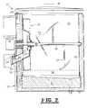
- FIG. 2 is a sectional side view displaying the interior of the storage bin and related components that comprise the ice- dispensing system of the preferred embodiment of the present invention.
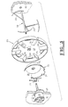
- FIG. 3 depicts an exploded view of the internal shaft and related components including an electric motor, a plurality of breaker bars, an ice retention device, the preferred embodiment of the rotating tray, and a plurality of agitators, all connected by pin means.
- FIG. 4 shows a side cut-away view of another embodiment of the present invention.
- FIG. 1 the preferred embodiment of the combination ice and beverage dispenser is generally depicted by numeral 10.
- On the external face of the dispenser is a plurality of beverages dispenser heads 11, and located adjacent to and at the same height as said beverage dispenser heads 11 is external ice discharge chute 12.
- Above external ice discharge chute 12 is electric motor 13 which is connected by electrical circuity with solenoid 14 and P.C. board 15.
- the cut-away portion of FIG. 1 gives a perspective view into the interior of the ice storage bin generally depicted by numeral 30.
- Inside bin 30 is shown internal shaft 19 with associated components, rotating tray 20, a plurality of breaker bars 21, an annular ice retention device 22, and a plurality of agitators 23.
- Forming the floor of ice storage bin 30 is cold plate 31.
- the walls of storage bin 30 are insulated with foam-in-place generally depicted by numeral 32. Molded in situ in said foam insulation 32 is a plurality of product lines 33, all within the confines of front wall 37.
- membrane switch 16 mounted onto external ice discharge chute 12 .
- membrane switch 16 When an operator desires to dispense ice, a beverage holder is placed below discharge chute 12 and membrane switch 16 is activated by minimal fingertip contact. Activation of switch 16 sends an electric signal to P.C. board 15 which activates solenoid 14 to lift a trap door (shown in FIG. 2 at numeral 17). Simultaneously with activation of solenoid 14, P.C. board 15 also signals motor 13 to rotate shaft 19 turns agitators 23 which slowly push stored ice in bin 30 forward into openings 24 connecting the interior of the storage bin with the inside of tray 20.
- FIG. 2 motor 13 turns shaft 19 which rotates tray 20. This rotation brings ice up from the lower portions of bin 30 towards the apex of rotating tray 20 which is well above the height of external discharge chute 12.
- FIG. 3 an exploded perspective view of the associated components of shaft 19 is depicted, showing the ice retention device 22 with a cut-away segment 25 at an upper quadrant of its rim 35.
- rotating tray 20 is shown with a plurality of molded vanes 26 which rise perpendicularly from circular base portion 27. Openings 24 communicate the inside of tray 20 with storage bin 30. Molded vanes 26, circular base portion 28, and the rim portion 35 of the ice retention device 22 form wedge-shaped cavities which carry ice pushed through openings 24 up towards the apex of tray 20.
- the force of gravity drops said ice into the confines of cone chute 22.
- breaker bars 21 further rotate the ice and push it down wall chute 28 which forms a connection with the external discharge chute 12 through the front wall 37 of the dispenser.
- Trap door 17 separates wall chute 28 from external discharge chute 12. Since trap door 17 remains open while membrane switch 16 is activated, ice is freely discharged past it and through to external discharge chute 12 and down into a waiting beverage holder. When the operator deactivates membrane switch 16, trap door 17 closes and simultaneously stops motor 13, along with shaft 19 and all components inside storage bin 30 mounted onto shaft 19.
- lid 18 When the level of ice in storage bin 30 drops sufficiently low to require refilling of the bin, lid 18 is lifted for access into the bin. Lifting of lid 18 activates interlock switch 29 which shuts off motor 13 should it be operational while lid 18 is open. This prevents any accidental injury that might occur to an operator either during refilling or during routine cleaning and maintenance of internal components.
- cold plate 31 is shown forming the floor of ice bin 30.
- cold plate 31 Within cold plate 31 is a plurality of product lines 33 shown in transverse sections.
- a layer of ice 36 is allowed to cover cold plate 31 undisturbed by agitators 23 and tray 20. This layer of ice cools cold plate 31 which chills product lines 33 while within the cold plate.
- product lines 33 extend beyond cold plate 31 and rise vertically to the external front face of dispenser 10. In this region, beyond the confines of cold plate 31, product lines 33 have the potential of warming up, which could result in an occasional warm beverage being dispensed.
- Foam-in-place 32 within the front wall 37 insulates the product lines and prevents this possibility of warming.
- FIG. 4 another embodiment of the rotating tray is shown.
- This embodiment is of a two-piece molded construction, the first piece generally designated with the numeral 43 and and the second piece by the numeral 42.
- First piece 43 has a first circular base portion 39 and a circular flange 41 which is contigous with the outer circumference of first circular base portion 41 and extends at a ninty-degree angle from said base portion 41 into the interior of storage bin 30.
- the second piece 42 is comprised of a plurality of vanes 38 which rise perpendicularily from a second circular base portion 40.
- a plurality of wedge-shaped pocket compartments are formed with first circular base portion 39 as the floor, rim portion 35 of ice retention device 22 forming an inner circular wall, circular flange 41 forming an outer circular wall, second circular base portion 40 forming the ceiling, and the plurality of vanes 38 forming walls dividing said pockets.
Landscapes
- Engineering & Computer Science (AREA)
- Physics & Mathematics (AREA)
- Mechanical Engineering (AREA)
- Thermal Sciences (AREA)
- General Engineering & Computer Science (AREA)
- Devices For Dispensing Beverages (AREA)
- Confectionery (AREA)
- Non-Alcoholic Beverages (AREA)
- Devices That Are Associated With Refrigeration Equipment (AREA)
- Beverage Vending Machines With Cups, And Gas Or Electricity Vending Machines (AREA)
Claims (13)
- Kombinierte Eis- und Getränke-Ausgabevorrichtung mit:einer Kammer (30) zum Speichern von Eis;einer kreisförmigen Hubanordnung mit einem kreisförmigen Drehkorb (20) und einer stationären, ringförmigen Eis-Rückhaltevorrichtung (22), die zentrisch mit Bezug auf den kreisförmigen Drehkorb (20) montiert ist, und einer Mehrzahl von Flügeln (26), die sich in dem Korb (20) befinden und die sich axial in Richtung auf die Eis-Rückhaltevorrichtung (22) erstrecken, wobei die Eis-Rückhaltevorrichtung (22) mit einer Öffnung (25) versehen ist, die mit dem Inneren des Drehkorbs (20) in Verbindung steht;einer Anordnung (19) zum Drehen des kreisförmigen Drehkorbes (20) derart, daß auf den Flügeln (26) abgelagertes Eis von einem untersten Teil der Kammer (30) zwecks Ausgabe in die Eis-Rückhaltevorrichtung (22) durch die Öffnung (25) hindurch angehoben wird; undeiner Eis-Abgabeanordnung (12), die unterhalb der Mittellinie der kreisförmigen Hubanordnung sitzt und mit der ringförmigen Eis-Rückhaltevorrichtung in Verbindung steht, um Eis zur Außenseite der Kammer abzugeben.
- Kombinierte Eis- und Getränke-Ausgabevorrichtung nach Anspruch 1, ferner versehen mit:
einer Anordnung (23) zum Bewegen von Eis nach vorne in Richtung auf die kreisförmige Hubanordnung (20, 22), derart, daß Eis von der Kammer (30) in die kreisförmige Hubanordnung eingebracht wird, wobei die Anordnung (23) zum Bewegen von Eis derart ausgebildet ist, daß sie gleichzeitig mit dem Aktivieren der Anordnung (13) zum Drehen des kreisförmigen Drehkorbs in Gang gesetzt wird. - Kombinierte Eis- und Getränke-Ausgabevorrichtung nach Anspruch 2, wobei:die Eis-Abgabeanordnung (12) eine Wandrutsche (28), eine Falltür (17) und eine externe Ausgaberutsche (12) aufweist und die Falltür (17) zwischen der Wandrutsche (28) und der externen Ausgaberutsche (12) angeordnet ist; unddie Anordnung (21, 23) zum Bewegen von Eis sowie die Anordnung (13) zum Drehen des kreisförmigen Drehkorbs und die Falltür (17) so ausgebildet sind, daß sie mittels einer einzigen Betätigungsquelle (16) in Gang gesetzt werden.
- Kombinierte Eis- und Getränke-Ausgabevorrichtung nach Anspruch 3, bei der die Anordnung (21, 23) zum Bewegen von Eis mittels der einzigen Betätigungsquelle in Zeitintervallen unabhängig in Gang gesetzt wird, ohne daß die Anordnung zum Drehen des kreisförmigen Drehkorbs (20) aktiviert wird und ohne daß die Falltür (17) aktiviert wird.
- Kombinierte Eis- und Getränke-Ausgabevorrichtung nach Anspruch 1, bei der die Kammer (30) von einem Boden (31), vier Seitenwänden (37), die im wesentlichen gleichförmig lotrecht zu dem Boden verlaufen, und einem abnehmbaren Deckel (18) gebildet ist.
- Kombinierte Eis- und Getränke-Ausgabevorrichtung nach Anspruch 5, bei welcher der Boden der Kammer eine Kühlplatte (31) trägt, die aus einem Metall mit effizientem Wärmeübergang besteht, wobei in das gegossene Metall mit effizientem Wärmeübergang eine Mehrzahl von Produktleitungen (33) derart eingeformt ist, daß durch Kühlen der Kühlplatte (31) die Produktleitungen gekühlt werden.
- Kombinierte Eis- und Getränke-Ausgabevorrichtung nach Anspruch 5, bei welcher die vier Seitenwände der Kammer jeweils mit Hohlräumen versehen sind, die mit Schaum-Isolierstoff (32) gefüllt sind, wobei in mindestens einer (37) der vier Seitenwände eine Mehrzahl von Produktleitungen (33) angeordnet ist, die in den Schaum-Isolierstoff (32) eingebettet sind.
- Kombinierte Eis- und Getränke-Ausgabevorrichtung mit:einer Kammer (30) zum Speichern von Eis, wobei die Kammer aus einem Boden (31), vier Seitenwänden (37) von im wesentlichen gleichförmiger Höhe, und einem abnehmbaren Deckel (18) gebildet ist, wobei der Boden eben ist und gleichförmig lotrecht zu den Seitenwänden steht, gekennzeichnet durch:eine Wandrutsche (28), die durch mindestens eine der Seitenwände hindurchragt und mit einer externen Ausgaberutsche (12) in Verbindung steht, und eine Falltür (17), die zwischen der Wandrutsche (28) und der externen Ausgaberutsche (12) sitzt;eine benachbart mindestens einer der Seitenwände angeordnete Hubanordnung (22, 42, 43), die einen kreisförmigen Drehkorb (42, 43) mit einem im wesentlichen der vollen Höhe und Breite der Seitenwände (37) entsprechenden Durchmesser und eine stationäre Eis-Rückhaltevorrichtung (22) aufweist, die innerhalb des zentralen Teils des kreisförmigen Drehkorbs (42, 43) derart angeordnet ist, daß die Kammer (30) mit dem kreisförmigen Drehkorb (42, 43) in Verbindung steht, wobei der kreisförmige Drehkorb mit der stationären Eis-Rückhaltevorrichtung (22) in Verbindung steht, die stationäre Eis-Rückhaltevorrichtung (22) mit dem Außenraum der Kammer (30) über die Wandrutsche (28) und die externe Ausgaberutsche (12) in Verbindung steht und die Rutsche (12) unterhalb der Mittellinie der Hubanordnung (22, 42, 43) angeordnet ist;eine Mehrzahl von Flügeln (38), die unter einem rechten Winkel mit dem kreisförmigen Drehkorb (42, 43) verbunden sind;eine Anordnung (28) zum Bewegen von innerhalb der Kammer gespeichertem Eis in Richtung auf den kreisförmigen Drehkorb zum Einbringen des Eises durch Öffnungen (25) in den kreisförmigen Drehkorb (42, 43) von den unteren Bereichen der Kammer; undeine Anordnung (19) zum Drehen des kreisförmigen Drehkorbs derart, daß der kreisförmige Drehkorb das abgelagerte Eis von den unteren Bereichen der Kammer (30) nach oben zu der stationären Eis-Rückhaltevorrichtung (22) anhebt, so daß das Eis über die Wandrutsche (28) und die externe Ausgaberutsche (12) vom Innenraum zur Außenseite der Kammer (30) ausgegeben wird.
- Kombinierte Eis- und Getränke-Ausgabevorrichtung nach Anspruch 8, bei welcher der kreisförmige Drehkorb (20) versehen ist mit:einem kreisförmigen, ebenen Basisteil (39), das eine Mehrzahl von ausgestanzten Randteilen aufweist; undeinem kreisförmigen Flanschteil, das mit dem gesamten Außenumfang des kreisförmigen ebenen Basisteils derart verbunden ist, daß von der Mehrzahl von Flügeln 38, dem kreisförmigen Flansch (41) und dem ebenen Basisteil (39) eine Mehrzahl von Taschen gebildet wird, wobei jede der Mehrzahl von keilförmigen Taschen mindestens eines der Mehrzahl von ausgestanzten Randteilen aufweist.
- Kombinierte Eis- und Getränke-Ausgabevorrichtung nach Anspruch 8, bei welcher der kreisförmige Drehkorb versehen ist mit:einem ersten kreisförmigen ebenen Basisteil (43), das eine Mehrzahl von ausgestanzten Randteilen aufweist;einer Mehrzahl von Flügeln (38), die unter einem rechten Winkel mit dem ersten kreisförmigen ebenen Basisteil (43) verbunden sind; undeinem zweiten kreisförmigen ebenen Basisteil (42) mit einem kreisförmigen Flanschteil (41), das mit dem gesamten Außenumfang des zweiten kreisförmigen ebenen Basisteils (42) derart verbunden ist, daß von dem ersten kreisförmigen ebenen Basisteil (43), der Mehrzahl von Flügeln (38), dem kreisförmigen Flansch (41) und dem zweiten kreisförmigen ebenen Basisteil (42) eine Mehrzahl von keilförmigen Taschen gebildet wird, wobei jede der Mehrzahl von keilförmigen Taschen mindestens eines der Mehrzahl von ausgestanzten Randteilen aufweist.
- Kombinierte Eis- und Getränke-Ausgabevorrichtung nach Anspruch 8, bei welcher die Falltür (17), die Anordnung zum Bewegen von Eis (21, 23) und die Anordnung zum Drehen des kreisförmigen Drehkorbs mittels einer einzigen Betätigungsquelle (16) alle gleichzeitig in Gang gesetzt werden.
- Kombinierte Eis- und Getränke-Ausgabevorrichtung nach Anspruch 8, bei der die Anordnung zum Bewegen von Eis versehen ist mit:einer langgestreckten Welle (19); undeiner Mehrzahl von Rührgliedern (21, 23), die an der langgestreckten Welle angebracht sind, wobei die langgestreckte Welle (19) und die Mehrzahl von Rührgliedern (21, 23) mit einem schlecht wärmeleitenden Werkstoff beschichtet sind, so daß Eis nicht an der Anordnung zum Bewegen von Eis anhaften kann.
- Kombinierte Eis- und Getränke-Ausgabevorrichtung nach Anspruch 8, bei welcher die innerhalb des zentralen Teils des kreisförmigen Drehkorbs (20) sitzende stationäre Eis-Rückhaltevorrichtung (22) versehen ist mit:einem kreisförmigen Basisteil; undeinem hochstehenden Randteil (35), das mit einem wesentlichen Teil des Umfangs des kreisförmigen Basisteils verbunden ist, wobei mindestens ein oberer Quadrant (25) des hochstehenden Randteils fehlt, so daß Eis durch diesen einen oberen Quadrant (25) hindurchfallen kann.
Applications Claiming Priority (3)
| Application Number | Priority Date | Filing Date | Title |
|---|---|---|---|
| US07/436,915 US5054654A (en) | 1989-11-14 | 1989-11-14 | Combination ice and chilled beverage dispenser |
| US436915 | 1989-11-14 | ||
| PCT/US1990/006645 WO1991007346A1 (en) | 1989-11-14 | 1990-11-14 | Combination ice and chilled beverage dispenser |
Publications (3)
| Publication Number | Publication Date |
|---|---|
| EP0534969A1 EP0534969A1 (de) | 1993-04-07 |
| EP0534969A4 EP0534969A4 (en) | 1993-05-19 |
| EP0534969B1 true EP0534969B1 (de) | 1996-03-20 |
Family
ID=23734326
Family Applications (1)
| Application Number | Title | Priority Date | Filing Date |
|---|---|---|---|
| EP90917261A Expired - Lifetime EP0534969B1 (de) | 1989-11-14 | 1990-11-14 | Automat zur kombinierten ausgabe von eis und gekühlten getränken |
Country Status (10)
| Country | Link |
|---|---|
| US (1) | US5054654A (de) |
| EP (1) | EP0534969B1 (de) |
| JP (1) | JPH05502206A (de) |
| AU (1) | AU652925B2 (de) |
| BR (1) | BR9007842A (de) |
| CA (1) | CA2068656C (de) |
| DE (1) | DE69026116T2 (de) |
| ES (1) | ES2086419T3 (de) |
| MX (1) | MX169393B (de) |
| WO (1) | WO1991007346A1 (de) |
Families Citing this family (29)
| Publication number | Priority date | Publication date | Assignee | Title |
|---|---|---|---|---|
| US5230448A (en) * | 1991-07-24 | 1993-07-27 | Lancer Corporation | Complete system self-contained drink and ice dispensing |
| US5244020A (en) * | 1991-07-24 | 1993-09-14 | Middleby Marshall Inc. | Dispenser |
| US5299716A (en) * | 1992-10-19 | 1994-04-05 | Lancer Corporation | Ice dispenser with an ice flow regulator |
| EP1291315A3 (de) * | 1995-02-15 | 2003-07-02 | Lancer Corporation | Eisausgabegerät und Gerät zur kombinierten Ausgabe von Eis und Getränken |
| IT237342Y1 (it) * | 1995-12-15 | 2000-09-05 | Castel Mac Spa | Macchina per l'erogazione di cubetti di ghiaccio |
| US6321802B1 (en) | 1999-06-14 | 2001-11-27 | Scotsman Group, Inc. | Ice and beverage dispensing apparatus |
| US6591877B1 (en) * | 1999-12-01 | 2003-07-15 | Hoshizaki America, Inc. | Beverage dispenser unit |
| DE10062664A1 (de) * | 2000-12-15 | 2002-07-18 | Bsh Bosch Siemens Hausgeraete | Sammelbehälter für Stückgut |
| RU2338133C2 (ru) * | 2003-03-28 | 2008-11-10 | Эл Джи Электроникс Инк. | Холодильник |
| US7186087B2 (en) * | 2004-05-19 | 2007-03-06 | Lancer Partnership, Ltd. | Method and apparatus for a dispensing system with a dual direction paddlewheel |
| US20060027599A1 (en) * | 2004-07-21 | 2006-02-09 | Lancer Partnership, Ltd. | Method and apparatus for dispensing compressed ice |
| EP1938030A2 (de) * | 2005-09-02 | 2008-07-02 | Manitowoc Foodservice Companies, Inc. | Eis-/getränke-spender mit in-line eishacker |
| US8247556B2 (en) * | 2005-10-21 | 2012-08-21 | Amgen Inc. | Method for preparing 6-substituted-7-aza-indoles |
| US20080128458A1 (en) * | 2006-10-24 | 2008-06-05 | Imi Cornelius Inc. | Ice dispense system and method |
| US20100294618A1 (en) * | 2007-07-30 | 2010-11-25 | Akoona, Llc | Ice Agitation and Dispensing Device and Method |
| NZ583283A (en) * | 2007-07-30 | 2012-05-25 | Akoona Llc | Device for dispensing a measured amount of ice from an ice making machine using a rotating drum with an opening |
| US8365956B2 (en) * | 2008-05-27 | 2013-02-05 | Lancer Corporation | Method and apparatus for a beverage dispenser |
| US8640483B2 (en) * | 2009-12-14 | 2014-02-04 | Whirlpool Corporation | Ice guide funnel |
| US8881952B1 (en) | 2010-10-11 | 2014-11-11 | K-Tec, Inc. | Ice dispensing and metering system and methods |
| JP5701161B2 (ja) * | 2011-06-15 | 2015-04-15 | ホシザキ電機株式会社 | 撹拌機構 |
| US20140061232A1 (en) * | 2012-08-29 | 2014-03-06 | Manitowoc Foodservice Companies, Llc | Method and apparatus for portioning and delivering ice |
| US9249006B2 (en) * | 2013-04-25 | 2016-02-02 | Cornelius, Inc. | Multi-nozzle beverage dispenser with slurry ice cooling system |
| FR3040772B1 (fr) * | 2015-09-07 | 2018-08-03 | Michele Rossi | Distributeur de glacons. |
| WO2017113486A1 (zh) * | 2015-12-31 | 2017-07-06 | 海信容声(广东)冰箱有限公司 | 一种碎冰装置及冰箱 |
| US12259170B2 (en) | 2015-12-31 | 2025-03-25 | Hisense Ronshen (Guangdong) Refrigerator Co., Ltd. | Refrigerator |
| FR3082293B1 (fr) * | 2018-06-12 | 2020-05-15 | Mk Ice | Distributeur de glacon ameliore |
| FR3128519B1 (fr) * | 2021-10-21 | 2023-12-15 | Rossi Michele | Distributeur de glaçons |
| US12163719B2 (en) * | 2022-05-12 | 2024-12-10 | Ice House America, Llc | Combination bagger |
| US20240191927A1 (en) * | 2022-12-13 | 2024-06-13 | Marmon Foodservice Technologies, Inc. | Ice dispensers |
Family Cites Families (10)
| Publication number | Priority date | Publication date | Assignee | Title |
|---|---|---|---|---|
| US3592366A (en) * | 1969-05-28 | 1971-07-13 | Borg Warner | Ice storage and dispensing apparatus |
| US3874559A (en) * | 1974-01-16 | 1975-04-01 | John J Pink | Ice dispenser for freezer-refrigerators and the like |
| US4555045A (en) * | 1983-09-30 | 1985-11-26 | The Coca-Cola Company | Ice-cooled dispensing system |
| US4641763A (en) * | 1984-05-18 | 1987-02-10 | Servend International | Ice and beverage dispensing apparatus and method with dual purpose liner |
| US4632280A (en) * | 1984-09-25 | 1986-12-30 | White Consolidated Industries, Inc. | Ice dispensing mechanism |
| US4679715A (en) * | 1985-09-06 | 1987-07-14 | Schneider Metal Manufacturing Co. | Ice cube dispensing outlet |
| GB8606427D0 (en) * | 1986-03-15 | 1986-04-23 | Wagner M | Dispensers |
| US4787539A (en) * | 1986-06-19 | 1988-11-29 | Hoshizaki Electric Co., Ltd. | Ice dispenser |
| US4803850A (en) * | 1988-02-22 | 1989-02-14 | Schneider Metal Manufacturing Co. | Apparatus and method of dispensing particulate ice and cold beverage with irreversible separation of cooling ice |
| US4921149A (en) * | 1988-06-09 | 1990-05-01 | Remcor Products Company | Ice portion control for ice dispenser and method |
-
1989
- 1989-11-14 US US07/436,915 patent/US5054654A/en not_active Expired - Lifetime
-
1990
- 1990-11-14 ES ES90917261T patent/ES2086419T3/es not_active Expired - Lifetime
- 1990-11-14 AU AU67567/90A patent/AU652925B2/en not_active Ceased
- 1990-11-14 DE DE69026116T patent/DE69026116T2/de not_active Expired - Fee Related
- 1990-11-14 EP EP90917261A patent/EP0534969B1/de not_active Expired - Lifetime
- 1990-11-14 WO PCT/US1990/006645 patent/WO1991007346A1/en not_active Ceased
- 1990-11-14 JP JP3500571A patent/JPH05502206A/ja active Pending
- 1990-11-14 CA CA002068656A patent/CA2068656C/en not_active Expired - Fee Related
- 1990-11-14 BR BR909007842A patent/BR9007842A/pt not_active IP Right Cessation
- 1990-11-14 MX MX023340A patent/MX169393B/es unknown
Also Published As
| Publication number | Publication date |
|---|---|
| JPH05502206A (ja) | 1993-04-22 |
| WO1991007346A1 (en) | 1991-05-30 |
| AU6756790A (en) | 1991-06-13 |
| EP0534969A4 (en) | 1993-05-19 |
| BR9007842A (pt) | 1992-09-08 |
| DE69026116T2 (de) | 1996-10-31 |
| AU652925B2 (en) | 1994-09-15 |
| EP0534969A1 (de) | 1993-04-07 |
| US5054654A (en) | 1991-10-08 |
| MX169393B (es) | 1993-06-30 |
| CA2068656C (en) | 1995-06-27 |
| ES2086419T3 (es) | 1996-07-01 |
| DE69026116D1 (de) | 1996-04-25 |
Similar Documents
| Publication | Publication Date | Title |
|---|---|---|
| EP0534969B1 (de) | Automat zur kombinierten ausgabe von eis und gekühlten getränken | |
| US5299716A (en) | Ice dispenser with an ice flow regulator | |
| US3913343A (en) | Sanitary ice storage and dispensing apparatus and method | |
| CA2113994C (en) | Complete soda system | |
| US5104007A (en) | Ice and beverage dispensing apparatus | |
| AU702994B2 (en) | Ice dispenser and combination ice and beverage dispenser | |
| US6321802B1 (en) | Ice and beverage dispensing apparatus | |
| US6772675B2 (en) | Apparatus for preparing frozen drinks | |
| US3858765A (en) | Dispensing apparatus | |
| US5058773A (en) | Beverage and ice dispensing method and apparatus | |
| US5025840A (en) | Ice cream dispensing machine | |
| US11454438B2 (en) | Space saving ice and beverage dispenser with accessible auger drive | |
| JPH10506080A (ja) | 飲料冷却装置 | |
| WO2017214377A1 (en) | Beverage dispenser | |
| US3393716A (en) | Multiple drink mixer and dispenser | |
| JP2838934B2 (ja) | カップ式自動販売機の飛散原料用受け皿の構造およびその支持構造 | |
| CA2314327C (en) | Ice dispenser and combination ice and beverage dispenser | |
| KR200232297Y1 (ko) | 슬러시 즉석 제빙장치 | |
| GB2188907A (en) | Improved ice-cooled drink dispensing system |
Legal Events
| Date | Code | Title | Description |
|---|---|---|---|
| PUAI | Public reference made under article 153(3) epc to a published international application that has entered the european phase |
Free format text: ORIGINAL CODE: 0009012 |
|
| 17P | Request for examination filed |
Effective date: 19920525 |
|
| AK | Designated contracting states |
Kind code of ref document: A1 Designated state(s): DE ES FR GB IT |
|
| A4 | Supplementary search report drawn up and despatched |
Effective date: 19930401 |
|
| AK | Designated contracting states |
Kind code of ref document: A4 Designated state(s): DE ES FR GB IT |
|
| 17Q | First examination report despatched |
Effective date: 19930818 |
|
| GRAH | Despatch of communication of intention to grant a patent |
Free format text: ORIGINAL CODE: EPIDOS IGRA |
|
| GRAA | (expected) grant |
Free format text: ORIGINAL CODE: 0009210 |
|
| AK | Designated contracting states |
Kind code of ref document: B1 Designated state(s): DE ES FR GB IT |
|
| REF | Corresponds to: |
Ref document number: 69026116 Country of ref document: DE Date of ref document: 19960425 |
|
| ET | Fr: translation filed | ||
| ITF | It: translation for a ep patent filed | ||
| REG | Reference to a national code |
Ref country code: ES Ref legal event code: FG2A Ref document number: 2086419 Country of ref document: ES Kind code of ref document: T3 |
|
| PLBE | No opposition filed within time limit |
Free format text: ORIGINAL CODE: 0009261 |
|
| STAA | Information on the status of an ep patent application or granted ep patent |
Free format text: STATUS: NO OPPOSITION FILED WITHIN TIME LIMIT |
|
| 26N | No opposition filed | ||
| REG | Reference to a national code |
Ref country code: GB Ref legal event code: IF02 |
|
| PGFP | Annual fee paid to national office [announced via postgrant information from national office to epo] |
Ref country code: GB Payment date: 20021030 Year of fee payment: 13 |
|
| PGFP | Annual fee paid to national office [announced via postgrant information from national office to epo] |
Ref country code: FR Payment date: 20021104 Year of fee payment: 13 |
|
| PGFP | Annual fee paid to national office [announced via postgrant information from national office to epo] |
Ref country code: DE Payment date: 20021111 Year of fee payment: 13 |
|
| PGFP | Annual fee paid to national office [announced via postgrant information from national office to epo] |
Ref country code: ES Payment date: 20021115 Year of fee payment: 13 |
|
| PG25 | Lapsed in a contracting state [announced via postgrant information from national office to epo] |
Ref country code: GB Free format text: LAPSE BECAUSE OF NON-PAYMENT OF DUE FEES Effective date: 20031114 |
|
| PG25 | Lapsed in a contracting state [announced via postgrant information from national office to epo] |
Ref country code: ES Free format text: LAPSE BECAUSE OF NON-PAYMENT OF DUE FEES Effective date: 20031115 |
|
| PG25 | Lapsed in a contracting state [announced via postgrant information from national office to epo] |
Ref country code: DE Free format text: LAPSE BECAUSE OF NON-PAYMENT OF DUE FEES Effective date: 20040602 |
|
| GBPC | Gb: european patent ceased through non-payment of renewal fee |
Effective date: 20031114 |
|
| PG25 | Lapsed in a contracting state [announced via postgrant information from national office to epo] |
Ref country code: FR Free format text: LAPSE BECAUSE OF NON-PAYMENT OF DUE FEES Effective date: 20040730 |
|
| REG | Reference to a national code |
Ref country code: FR Ref legal event code: ST |
|
| REG | Reference to a national code |
Ref country code: ES Ref legal event code: FD2A Effective date: 20031115 |
|
| PG25 | Lapsed in a contracting state [announced via postgrant information from national office to epo] |
Ref country code: IT Free format text: LAPSE BECAUSE OF NON-PAYMENT OF DUE FEES;WARNING: LAPSES OF ITALIAN PATENTS WITH EFFECTIVE DATE BEFORE 2007 MAY HAVE OCCURRED AT ANY TIME BEFORE 2007. THE CORRECT EFFECTIVE DATE MAY BE DIFFERENT FROM THE ONE RECORDED. Effective date: 20051114 |