EP0534686A1 - Joint-brosse disposé dans une gorge - Google Patents
Joint-brosse disposé dans une gorge Download PDFInfo
- Publication number
- EP0534686A1 EP0534686A1 EP92308492A EP92308492A EP0534686A1 EP 0534686 A1 EP0534686 A1 EP 0534686A1 EP 92308492 A EP92308492 A EP 92308492A EP 92308492 A EP92308492 A EP 92308492A EP 0534686 A1 EP0534686 A1 EP 0534686A1
- Authority
- EP
- European Patent Office
- Prior art keywords
- seal
- disposed
- static structure
- brush
- invention according
- Prior art date
- Legal status (The legal status is an assumption and is not a legal conclusion. Google has not performed a legal analysis and makes no representation as to the accuracy of the status listed.)
- Withdrawn
Links
Images


Classifications
-
- F—MECHANICAL ENGINEERING; LIGHTING; HEATING; WEAPONS; BLASTING
- F02—COMBUSTION ENGINES; HOT-GAS OR COMBUSTION-PRODUCT ENGINE PLANTS
- F02C—GAS-TURBINE PLANTS; AIR INTAKES FOR JET-PROPULSION PLANTS; CONTROLLING FUEL SUPPLY IN AIR-BREATHING JET-PROPULSION PLANTS
- F02C7/00—Features, components parts, details or accessories, not provided for in, or of interest apart form groups F02C1/00 - F02C6/00; Air intakes for jet-propulsion plants
- F02C7/28—Arrangement of seals
-
- F—MECHANICAL ENGINEERING; LIGHTING; HEATING; WEAPONS; BLASTING
- F16—ENGINEERING ELEMENTS AND UNITS; GENERAL MEASURES FOR PRODUCING AND MAINTAINING EFFECTIVE FUNCTIONING OF MACHINES OR INSTALLATIONS; THERMAL INSULATION IN GENERAL
- F16J—PISTONS; CYLINDERS; SEALINGS
- F16J15/00—Sealings
- F16J15/16—Sealings between relatively-moving surfaces
- F16J15/32—Sealings between relatively-moving surfaces with elastic sealings, e.g. O-rings
- F16J15/3284—Sealings between relatively-moving surfaces with elastic sealings, e.g. O-rings characterised by their structure; Selection of materials
- F16J15/3288—Filamentary structures, e.g. brush seals
-
- F—MECHANICAL ENGINEERING; LIGHTING; HEATING; WEAPONS; BLASTING
- F01—MACHINES OR ENGINES IN GENERAL; ENGINE PLANTS IN GENERAL; STEAM ENGINES
- F01D—NON-POSITIVE DISPLACEMENT MACHINES OR ENGINES, e.g. STEAM TURBINES
- F01D11/00—Preventing or minimising internal leakage of working-fluid, e.g. between stages
- F01D11/001—Preventing or minimising internal leakage of working-fluid, e.g. between stages for sealing space between stator blade and rotor
-
- F—MECHANICAL ENGINEERING; LIGHTING; HEATING; WEAPONS; BLASTING
- F01—MACHINES OR ENGINES IN GENERAL; ENGINE PLANTS IN GENERAL; STEAM ENGINES
- F01D—NON-POSITIVE DISPLACEMENT MACHINES OR ENGINES, e.g. STEAM TURBINES
- F01D11/00—Preventing or minimising internal leakage of working-fluid, e.g. between stages
- F01D11/005—Sealing means between non relatively rotating elements
-
- F—MECHANICAL ENGINEERING; LIGHTING; HEATING; WEAPONS; BLASTING
- F01—MACHINES OR ENGINES IN GENERAL; ENGINE PLANTS IN GENERAL; STEAM ENGINES
- F01D—NON-POSITIVE DISPLACEMENT MACHINES OR ENGINES, e.g. STEAM TURBINES
- F01D11/00—Preventing or minimising internal leakage of working-fluid, e.g. between stages
- F01D11/02—Preventing or minimising internal leakage of working-fluid, e.g. between stages by non-contact sealings, e.g. of labyrinth type
-
- F—MECHANICAL ENGINEERING; LIGHTING; HEATING; WEAPONS; BLASTING
- F01—MACHINES OR ENGINES IN GENERAL; ENGINE PLANTS IN GENERAL; STEAM ENGINES
- F01D—NON-POSITIVE DISPLACEMENT MACHINES OR ENGINES, e.g. STEAM TURBINES
- F01D5/00—Blades; Blade-carrying members; Heating, heat-insulating, cooling or antivibration means on the blades or the members
- F01D5/02—Blade-carrying members, e.g. rotors
- F01D5/08—Heating, heat-insulating or cooling means
- F01D5/081—Cooling fluid being directed on the side of the rotor disc or at the roots of the blades
- F01D5/082—Cooling fluid being directed on the side of the rotor disc or at the roots of the blades on the side of the rotor disc
-
- F—MECHANICAL ENGINEERING; LIGHTING; HEATING; WEAPONS; BLASTING
- F16—ENGINEERING ELEMENTS AND UNITS; GENERAL MEASURES FOR PRODUCING AND MAINTAINING EFFECTIVE FUNCTIONING OF MACHINES OR INSTALLATIONS; THERMAL INSULATION IN GENERAL
- F16J—PISTONS; CYLINDERS; SEALINGS
- F16J15/00—Sealings
- F16J15/44—Free-space packings
- F16J15/447—Labyrinth packings
- F16J15/4472—Labyrinth packings with axial path
-
- F—MECHANICAL ENGINEERING; LIGHTING; HEATING; WEAPONS; BLASTING
- F05—INDEXING SCHEMES RELATING TO ENGINES OR PUMPS IN VARIOUS SUBCLASSES OF CLASSES F01-F04
- F05D—INDEXING SCHEME FOR ASPECTS RELATING TO NON-POSITIVE-DISPLACEMENT MACHINES OR ENGINES, GAS-TURBINES OR JET-PROPULSION PLANTS
- F05D2240/00—Components
- F05D2240/55—Seals
- F05D2240/56—Brush seals
Definitions
- the present invention relates generally to pressure seals in pas turbine engines and more specifically to an improved configuration brush seal apparatus for both dynamic and static sealing applications.
- seals between static and high speed rotating parts in a gas turbine engine presents a daunting challenge. Rotational speeds in excess of 30.000 rpm for gas generator rotors in small engines is not uncommon. In order that seal wear is minimized, seal elements can be spaced apart allowing for a small controlled amount of leakage flow; however, differing rates of thermal growth between rotor and static structures during transient operating conditions directly affects intercomponent clearances. Additionally, there are rotor eccentricities which must be accounted for as well as a limited amount of mechanical inertial growth. In order to provide an acceptable degree of sealing for both steady state and transient operating conditions, labyrinth seals are commonly used.
- the sharp toothed portion of the seal is mounted on the rotating component with an abradable honeycomb or other sacrificial material disposed radially outward to form the land.
- abradable honeycomb or other sacrificial material disposed radially outward to form the land.
- the sharp teeth wear permanent grooves in the land.
- leakage through the seal has increased. Excessive rubbing may cause overheating, degradation and wear of the rotating seal teeth themselves. further increasing leakage.
- those skilled in the art must compensate for seal degradation by providing sufficient margin in the secondary flow system.
- brush seals Another apparatus employed for sealing between high speed rotating and static parts is brush seals. These seals are comprised of a plurality of compliant bristles which extend generally radially inwardly from an annular ring to which they are permanently affixed. The ring is clamped or otherwise fixedly attached to a static member and circumscribes and is concentric with a rotating member or shaft. The crush. seal is sized so thai the bristles are biased against the shaft. often being canted in the direction of rotation of the shaft. During operation, the bristles rub against the shaft. compliantly deforming due to thermal growth and orbiting of the shaft, thereby maintaining their sealing capability. Unlike permanently grooved labyrinth seal lands, brush seals retain their sealing effectiveness after periods of reduced clearance.
- the present invention provides a brush seal apparatus comprising: brush seal means disposed between a high pressure zone and a lower pressure zone and fixedly attached to a first member; and a second member having a groove means for receiving a compliant portion of said seal means therein in close proximity to and spaced from internal surfaces of said groove means for restricting fluid flow between said high pressure zone and said lower pressure zone.
- the present invention provides a seal apparatus which exhibits improved life by substantially eliminating seal were thereby achieving a relatively constant steady state leakage flow.
- an appreciable increase in engine efficiency can be realized due to minimization of parasitic loss associated with secondary flow margin required to compensate for increasing leakage due to progressive seal were in systems with conventional sealing apparatuses.
- the seal apparatus is comprised of a conventional annular brush seal fixedly attached to a static structure.
- the distal ends of the radially inwardly directed compliant bristles are disposed in a groove or trench in an adjacent structure.
- the configuration is characterized by the absence of contact between the bristles and the adjacent structure in the nominal steady state, where a small, but finite clearance exists.
- the trenched structure may be substantially fixed with respect to the static structure, with relative movement being the result, for example. of vibration or variation in thermal growth, or the structure may rotate. In the nominal steady state, the amount of leakage is controlled by the resistance inherent in the narrow sizing and tortuosity of the circuitous path along which the fluid must travel.
- FIG. 1 Shown in Figure 1 is an annular brush seal apparatus 10 used for restricting fluid flow between a high pressure zone 12 and a lower pressure zone 14.
- the seal apparatus 10 is comprised of a conventional brush seal 16 and a cooperating rotating seal runner 18 fixedly attached to rotating shaft 20.
- the seal 16 and runner 18 are disposed concentrically about the axial rotational centerline 22 of the shaft 20.
- the seal apparatus 10 is shown enlarged relative to the shaft 20.
- the brush seal 16 is conventionally retained in a static supporting structure 24, for example, by an interference fit between the seal outer diameter 26 and an axial bore 28 in the static structure 24.
- a static clamping element 30 can be fixedly attached to structure 24 using bolts (not shown) or other equivalent means, the axial length L of bore 28 being less than the thickness T of seal 16 thereby leaving an axial gap G between structure 24 and element 30 to further ensure positive retention of the seal 16 when the bolts are tightened.
- the brush seal 16 is comprised of a plurality of densely compacted. generally radially disposed bristle elements 32 sandwiches between a first annular sideplate 34 and a second axially spaced annular sideplate 36.
- the bristle elements 32 and first and second sideplates, 34 and 36, are manufactured to form an inseparable assembly, for example by welding or brazing at the seal outer diameter 26.
- the seal 16 is conventionally utilized with the first sideplate 34 having a first radius R1 at its inner diameter and the second sideplate 36 having a second radiu R2 at its inner diameter, wherein R1 is greater than R2 and first sideplate 34 is disposed proximate high pressure zone 12 and second sideplate 36 is disposed proximate lower pressure zone 14.
- the rotating seal runner 18 is characterized as having a radius R3 at its outer diameter which is less than second radius R2.
- Bristle elements 32 collectively form an annulus having a fourth radius R4 at their inner diameter, where R4 is less than R3.
- an annular groove of limited axial length shown generally at 38, is disposed in runner 18.
- Groove 38 has a fifth radius R5 at its outer-diameter which is less than R4. ln summary, R1 is greater than R2 which is greater than R3 which is greater than R4 which is greater than R5.
- the distal ends 37 of bristle elements 32 are necessarily radially disposed in the annular groove 38 of the seal runner 18 and radially spaced apart from its inner radial surface 40, which is coincident with R5.
- Inner surface 40 may be further characterized by the presence of a conventional wear coating 42 of nominal thickness.
- a lead-in chamfer 44 can be provided on the seal runner 18 to aid in assembly of the annular seal 16 over the runner 18. It should be noted that the aforementioned dimensional relationships apply to nominal steady state operation of the equipment in which the seal apparatus 10 is installed.
- seal runner 18 is shown mounted on a rotating shaft 20 in Figure 1 for ease of representation, it is apparent that the seal apparatus 10 could be employed at any location on a rotor where labyrinth seals are conventionally utilized. Alternately, the groove could be machined directly in the shaft for low speed, low stress applications.
- FIG 2 shown is an enlarged portion of the seal apparatus 10 illustrated in Figure 1 with particular emphasis placed on the interaction between the bristle elements 32 and the seal runner 18. Additional components have been deleted for clarity.
- the radial immersion I of the distal ends 37 of the bristle elements 32 into annular groove 38 is the difference between R3 and R4.
- the overall radial clearance C between the distal ends 37 and the inner surface 40 of groove 38 is the difference between R4 and R5.
- the bristle elements 32 proximate the first annular sideplate 34 form a first bristle plane 32a which in part bounds high pressure zone 12.
- the elements 32 proximate the second sideplate 36 form a second bristle plane 32b which in part bounds lower pressure zone 14.
- the first plane 32a is spaced longitudinally from first annular groove sidewall 40a a first distance Ca
- second plane 32b is spaced longitudinally from second annular groove sidewall 40b a second distance Cb.
- Tortuosity is defined as the quantity and abruptness of flow direction changes of path 46. Further, resistance to flow is also a function of the size of the flow passages. in this case related to radial immersion 1, first distance Ca, radial clearance C, and second distance Cb. Additionally, the radially inward face 36a of second sideplate 36, which was previously defined as having a value of R2, further serves the purpose; providing additional resistance to flow by turning the leakage flow a final time.
- the radial clearance C be as small as possible.
- Primary considerations in sizing are the nominal steady state values of R4 and R5 as well as the radial runouts of the bristle element distal ends 37 and the groove inner radial surface 40, respectively. For a value or R5 of approximately six inches, cumulative runouts, and therefore a desirable value for the radial clearance C would be in the range of one to five mils.
- Radial immersion I must have a large enough value that during worst transient conditions of increased radial clearance C, the value of I remains positive.
- R3 should always be greater than R4.
- a typical value would be in the range of three to twenty mils. Excessively large values may cause plastic deformation of the bristle elements 37 or other difficulty during assembly adversely affecting resultant sealing capability. Further, it the pressure differential across the seal apparatus 10 is large, undesirable longitudinal deflection of the distal ends 37 may occur, as they are not fully supported by the second sideplate 36.
- the assembly problem could be overcome by forming the runner 18 out of two pieces, for example by splitting runner 18 along the radial plane 47 of the second annular sidewall 40b, shown in dotted line in Figure 2.
- R2 and R3 must be sized so that durug worst case transient periods of negative radial clearance C, or minimum radial immersion I. R2 remains greater than R3 to prevent detrimental contact between radially inward face 36a and the runner 18. For this example, a clearance value in the range of fifty to one hundred mils would be typical.
- first and second distances Ca and Cb must be sized such that contact between the first and second bristle planes, 32a and 32b, and first and second sidewalls, 40a and 40b, respectively, is avoided.
- First and second distances Ca and Cb however should be kept to a minimum to restrict flow as much as possible. In a gas turbine engine application, the values are generally different, as rotor shift in the forward and aft longitudinal directions is not uniform.
- a typical value for Ca would be thirty mils, to compensate for an aft rotor deflection. and for Cb, seventy mils to compensate for a forward rotor deflection.
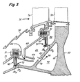
- seals 48 and 50 are fixedly attached to static forward and aft inner combustor casings 53 and 68 by a plurality of circumferentially spaced nut and bolt assemblies 51, although the interference fit clamped arrangement shown in Figure 1 could also be used.
- Respective bristle element distal ends 37a and 37b are disposed in respective annular grooves 38a and 38b in high pressure turbine (HPT) rotor 60.
- HPT high pressure turbine
- the rotor 60 is shown as being of unitary construction; however, it is representative of a conventional rotor assembly comprising one or more disks, blades, blade retainers and a gas generator shaft, operationally connected to a compressor.
- Secondary air is often used to pressurize core cavities to prevent thrust reversal on gas generator shaft bearings, offset the axial loads on the gas generator rotor caused by reaction of the rotor with the primary flow, as well as cool heated components.
- Hot primary flow combustion gases 52 bounded by the inner combustor liner 54 and outer combustor liner (not shown) pass through turbine nozzle 56 and are directed at a preferential angle to the blades 58 of the HPT rotor 60 for efficient work extraction.
- Relatively cool secondary air 62, at a higher pressure than primary gases 52 flows through accelerator 64 into a first pressure chamber 66.
- the accelerator 64 induces a circumferential flow component to secondary air 62 in order that it better match the rotational speed of rotor 60.
- First chamber 66 is bounded by IBP and OBP seals 48 and 50, rotor 60 and aft inner combustor casing 68.
- the flow of secondary air 62 divides into OBP seal leakage flow 70.
- Cooling flow 74 passes through apertures 76 in the rotor 60 into a second pressure chamber 78 before flowing radially outward into conventional blade cooling circuits (not shown) which are in fluid communication with second chamber 78.
- First and second generally radially extending faces 80 and 81 are sized in conjunction with the pressure in cavities 66 and 78 respectively to provide the proper balance force rotor 60.
- OBP seal leakage flow 70 is used to purge rotor cavity 82, preventing the ingress of hot gases 52 into cavity 82 which otherwise would cause a detrimental increase in the temperature and consequent reduction in life of the rotor 60.
- IBP seal leakage flow 72 is conventionally used to provide positive pressurization of other internal rotor cavities, for example, bearing sumps. While the source of secondary air 72 is shown to be from the combustor for ease of depiction. other lower pressure sources, such as various stages in the compressor could be utilized depending on the requirements of the particular gas turbine engine.
- FIG. 4a depicts a stator assembly 84 aft of the HPT rotor 60 which is conventionally comprised of shrouds 86 disposed radially outwardly of the blades 58 fixedly attached to a shroud support 88. After the hot combustion gases 52 pass by the blades 58, they are channeled downstream through transition duct 90 into a conventional low pressure turbine (not shown) for additional work extraction. A transition duct seal 92 is employed to allow a controlled amount of leakage from third pressure chamber 94 to purge zone 96 immediately drownstream of shrouds 86.
- High pressure air from chamber 94 passes through internal passages (not shown) in transition duct vanes 98 to cool the vanes 98 and provide pressurized air to internal engine cavities.
- the bristle element distal ends 37c of the brush seal apparatus utilized as duct seal 92 are disposed in annular groove 38c in an axially extending leg 100 of the transition duct 90. Seal 92 is conventionally retained in shroud support 88, for example by a slight interference fit. If warranted, additional attachment means could be employed.
- bristle elements 32d of circumferential transition duct seal 102 are generally axially oriented. Seal 102 is fixedly attached to transition duct 90a, its bristle element distal ends 37d being disposed in a downstream opening annular groove 38d in shroud support 88a. The function and operation of seal 102 is similar to that of seal 92 in Figure 4a.
- Figures 5a, 5b, and 5c depict alternate embodiments of the invention particularly suited for high pressure applications, or where leakage flow rates must be reduced further than the configurations heretofore described.
- the brush seal apparatus delineated in Figure 5a is comprised of two identical brush seals 116a and 116b for restricting flow between high pressure zone 112 and lower pressure zone 114. Seals 116a and 116b are configured in serial sealing relationship, having their respective bristle element distal ends 137a and 137b disposed in a common annular groove 138.
- the apparatus delineated is similarly configured as that in Figure 5a; however, distal ends 237a and 237b of respective brush seals 216a and 216b are disposed in distinct annular grooves 238a and 238b, respectively, in annular surface 218.
- This configuration having a more tortuous leakage path due to the projection 220, is more effective in reducing leakage flow rate for a given pressure drop between high pressure zone 212 and lower pressure zone 214 than that depicted in Figure 5a.
- Figure 5c shown is a stepped brush seal apparatus where two brush seals 316a und 316b are arranged in serial sealing relationship between high pressure zone 312 and lower pressure zone 314.
- Distal ends 337a and 337b are disposed in respective annular grooves 338a and 338b which are of differing radial dimension. This feature, while requiring seals of different sizes adds an additional degree of tortuosity to the leakage path increasing resistance to flow and thereby further reducing the volumetric leakage flow rate.
- the component in which the annular grooves are disposed may be of unitary construction or comprised of a plurality of elements to allow for ease of assembly and disassembly. Representative parting planes are shown as dotted lines 147, 247 and 347 in Figures 5a, 5b, and 5c respectively, although any of a variety of other planar locations could be chosen dependent on the particular configuration of the subject application.
- the brush seal may be comprised of a series of cooperating arcuate segments which collectively form a complete annular seal when installed.
- the embodiments shown in Figures 5a, 5b and 5c are applicable to dynamic as well as static sealing applications and can be used with radially or axially oriented brush seals.
- this invention has broad application in not only gas turbine engines. but in a wide variety of mechanical and other devices where conventional sealing apparatuses are used to restrict flow between zones of differing pressure. and is also particularly suited for use where contamination of the leakage flow caused by wear of the sealing apparatus is detrimental to the operation of the device.
Landscapes
- Engineering & Computer Science (AREA)
- General Engineering & Computer Science (AREA)
- Mechanical Engineering (AREA)
- Chemical & Material Sciences (AREA)
- Combustion & Propulsion (AREA)
- Sealing Devices (AREA)
- Turbine Rotor Nozzle Sealing (AREA)
Applications Claiming Priority (2)
| Application Number | Priority Date | Filing Date | Title |
|---|---|---|---|
| US764289 | 1985-08-12 | ||
| US07/764,289 US5181728A (en) | 1991-09-23 | 1991-09-23 | Trenched brush seal |
Publications (1)
| Publication Number | Publication Date |
|---|---|
| EP0534686A1 true EP0534686A1 (fr) | 1993-03-31 |
Family
ID=25070268
Family Applications (1)
| Application Number | Title | Priority Date | Filing Date |
|---|---|---|---|
| EP92308492A Withdrawn EP0534686A1 (fr) | 1991-09-23 | 1992-09-17 | Joint-brosse disposé dans une gorge |
Country Status (5)
| Country | Link |
|---|---|
| US (1) | US5181728A (fr) |
| EP (1) | EP0534686A1 (fr) |
| JP (1) | JPH086609B2 (fr) |
| KR (1) | KR950006875B1 (fr) |
| CA (1) | CA2075778C (fr) |
Cited By (12)
| Publication number | Priority date | Publication date | Assignee | Title |
|---|---|---|---|---|
| DE19519322A1 (de) * | 1995-05-26 | 1996-11-28 | Klein Schanzlin & Becker Ag | Dichtung zwischen Laufrad und Gehäusewand einer Kreiselpumpe |
| EP0840042A3 (fr) * | 1996-11-02 | 1999-07-21 | Mtu Motoren- Und Turbinen-Union MàNchen Gmbh | Joint à brosses pour dispositif rotor/stator. |
| WO2000045070A1 (fr) * | 1999-01-27 | 2000-08-03 | General Electric Company | Procede et dispositif de suppression du cintrage thermique de rotors de turbines a vapeur |
| WO2001055624A1 (fr) * | 2000-01-31 | 2001-08-02 | General Electric Company | Joints en brosses pour turbine a vapeur |
| DE10018273A1 (de) * | 2000-04-13 | 2001-10-25 | Mtu Aero Engines Gmbh | Bürstendichtung |
| EP1496196A1 (fr) * | 2003-07-08 | 2005-01-12 | Siemens Aktiengesellschaft | Turbine à vapeur |
| EP1508671A2 (fr) * | 1998-12-23 | 2005-02-23 | United Technologies Corporation | Joint à brosses pour une turbomachine |
| EP1767744A1 (fr) * | 2005-09-22 | 2007-03-28 | Siemens Aktiengesellschaft | Aube de turbine avec plaquette d'extrémité comprenant une couche dure soudée et procédé de fabrication |
| DE102009037393A1 (de) * | 2009-08-13 | 2011-02-17 | Man Diesel & Turbo Se | Strömungsmaschine |
| GB2536861A (en) * | 2014-12-17 | 2016-10-05 | Rolls Royce Plc | A gas turbine engine with a compliant filament seal arrangement |
| EP3173670A1 (fr) * | 2015-11-24 | 2017-05-31 | MTU Aero Engines GmbH | Système de joint balai pour une turbomachine, système de mise à la terre et turbomachine |
| EP3173587A1 (fr) * | 2015-11-30 | 2017-05-31 | MTU Aero Engines GmbH | Carter de turbomachine, element de verrouillage et turbomachine |
Families Citing this family (96)
| Publication number | Priority date | Publication date | Assignee | Title |
|---|---|---|---|---|
| US5400586A (en) * | 1992-07-28 | 1995-03-28 | General Electric Co. | Self-accommodating brush seal for gas turbine combustor |
| US5378000A (en) * | 1992-10-19 | 1995-01-03 | Inpro Companies, Inc. | Shaft seal assembly |
| US6131910A (en) * | 1992-11-19 | 2000-10-17 | General Electric Co. | Brush seals and combined labyrinth and brush seals for rotary machines |
| US6131911A (en) * | 1992-11-19 | 2000-10-17 | General Electric Co. | Brush seals and combined labyrinth and brush seals for rotary machines |
| US5474306A (en) | 1992-11-19 | 1995-12-12 | General Electric Co. | Woven seal and hybrid cloth-brush seals for turbine applications |
| US5749584A (en) * | 1992-11-19 | 1998-05-12 | General Electric Company | Combined brush seal and labyrinth seal segment for rotary machines |
| US5480162A (en) * | 1993-09-08 | 1996-01-02 | United Technologies Corporation | Axial load carrying brush seal |
| US5522698A (en) * | 1994-04-29 | 1996-06-04 | United Technologies Corporation | Brush seal support and vane assembly windage cover |
| US5498139A (en) * | 1994-11-09 | 1996-03-12 | United Technologies Corporation | Brush seal |
| GB2301635B (en) * | 1995-04-12 | 1998-09-16 | Gec Alsthom Ltd | Shaft seal arrangement |
| US5630590A (en) * | 1996-03-26 | 1997-05-20 | United Technologies Corporation | Method and apparatus for improving the airsealing effectiveness in a turbine engine |
| US5613829A (en) * | 1996-05-03 | 1997-03-25 | General Electric Company | Gas turbine subassembly having a brush seal |
| GB2313635A (en) * | 1996-05-30 | 1997-12-03 | Rolls Royce Plc | A seal arrangement |
| US7059827B1 (en) * | 1996-05-31 | 2006-06-13 | Watson Cogeneration Company | Turbine power plant having minimal-contact brush seal augmented labyrinth seal |
| DE19639328A1 (de) * | 1996-09-25 | 1998-03-26 | Asea Brown Boveri | Vorrichtung zur Dichtung eines Spaltes zwischen Rotor und Gehäuse einer Strömungsmaschine |
| EP0834688B1 (fr) * | 1996-10-02 | 2003-10-22 | MTU Aero Engines GmbH | Joint à brosses |
| DE19712088C2 (de) * | 1997-03-22 | 1999-06-24 | Mtu Muenchen Gmbh | Bürstendichtung mit in Umfangsrichtung schräg gestellten Borsten |
| US6027121A (en) * | 1997-10-23 | 2000-02-22 | General Electric Co. | Combined brush/labyrinth seal for rotary machines |
| US6045134A (en) * | 1998-02-04 | 2000-04-04 | General Electric Co. | Combined labyrinth and brush seals for rotary machines |
| US6139018A (en) * | 1998-03-25 | 2000-10-31 | General Electric Co. | Positive pressure-actuated brush seal |
| US6036437A (en) * | 1998-04-03 | 2000-03-14 | General Electric Co. | Bucket cover geometry for brush seal applications |
| US6808179B1 (en) | 1998-07-31 | 2004-10-26 | Concepts Eti, Inc. | Turbomachinery seal |
| US6168162B1 (en) | 1998-08-05 | 2001-01-02 | General Electric Co. | Self-centering brush seal |
| US6250640B1 (en) * | 1998-08-17 | 2001-06-26 | General Electric Co. | Brush seals for steam turbine applications |
| US6357752B1 (en) * | 1999-10-15 | 2002-03-19 | General Electric Company | Brush seal |
| US6290232B1 (en) * | 1999-11-16 | 2001-09-18 | General Electric Co. | Rub-tolerant brush seal for turbine rotors and methods of installation |
| US6331006B1 (en) | 2000-01-25 | 2001-12-18 | General Electric Company | Brush seal mounting in supporting groove using flat spring with bifurcated end |
| US6428009B2 (en) * | 2000-04-03 | 2002-08-06 | John F. Justak | Robust hydrodynamic brush seal |
| US6457719B1 (en) | 2000-08-14 | 2002-10-01 | United Technologies Corporation | Brush seal |
| US6345494B1 (en) * | 2000-09-20 | 2002-02-12 | Siemens Westinghouse Power Corporation | Side seal for combustor transitions |
| US6805358B2 (en) * | 2001-08-16 | 2004-10-19 | Isomag Corporation | Magnetic seal |
| US6622490B2 (en) * | 2002-01-11 | 2003-09-23 | Watson Cogeneration Company | Turbine power plant having an axially loaded floating brush seal |
| US6854735B2 (en) * | 2002-08-26 | 2005-02-15 | General Electric Company | In situ load sharing brush seals |
| GB2393766A (en) * | 2002-10-03 | 2004-04-07 | Alstom | A sealing arrangement for a turbine |
| US20040094900A1 (en) * | 2002-11-15 | 2004-05-20 | Turnquist Norman Arnold | Brush seal for static turbine components |
| US6761530B1 (en) * | 2003-03-21 | 2004-07-13 | General Electric Company | Method and apparatus to facilitate reducing turbine packing leakage losses |
| US8002285B2 (en) * | 2003-05-01 | 2011-08-23 | Justak John F | Non-contact seal for a gas turbine engine |
| US20040217549A1 (en) * | 2003-05-01 | 2004-11-04 | Justak John F. | Hydrodynamic brush seal |
| US7896352B2 (en) * | 2003-05-01 | 2011-03-01 | Justak John F | Seal with stacked sealing elements |
| US8172232B2 (en) * | 2003-05-01 | 2012-05-08 | Advanced Technologies Group, Inc. | Non-contact seal for a gas turbine engine |
| US8641045B2 (en) * | 2003-05-01 | 2014-02-04 | Advanced Technologies Group, Inc. | Seal with stacked sealing elements |
| US7410173B2 (en) * | 2003-05-01 | 2008-08-12 | Justak John F | Hydrodynamic brush seal |
| US8919781B2 (en) | 2003-05-01 | 2014-12-30 | Advanced Technologies Group, Inc. | Self-adjusting non-contact seal |
| US20060267289A1 (en) * | 2003-06-20 | 2006-11-30 | Elliott Company | Hybrid abradable labyrinth damper seal |
| US20070069477A1 (en) * | 2003-06-20 | 2007-03-29 | Elliott Company | Stepped labyrinth damper seal |
| DE10331601B4 (de) * | 2003-07-12 | 2019-06-06 | MTU Aero Engines AG | Dichtungsanordnung und Verfahren zur Herstellung derselben |
| US6887038B2 (en) * | 2003-09-02 | 2005-05-03 | General Electric Company | Methods and apparatus to facilitate sealing between rotating turbine shafts |
| US7562880B2 (en) * | 2004-02-09 | 2009-07-21 | Siemens Energy, Inc. | Seal usable between thermally movable components |
| US7249928B2 (en) * | 2005-04-01 | 2007-07-31 | General Electric Company | Turbine nozzle with purge cavity blend |
| US20070132190A1 (en) * | 2005-12-12 | 2007-06-14 | Charles Trabert | Axial dynamic brush seal |
| US20070132193A1 (en) * | 2005-12-13 | 2007-06-14 | Wolfe Christopher E | Compliant abradable sealing system and method for rotary machines |
| EP1813840A1 (fr) * | 2006-01-26 | 2007-08-01 | Siemens Aktiengesellschaft | Joint de brosse à plusieurs étages |
| US7445424B1 (en) | 2006-04-22 | 2008-11-04 | Florida Turbine Technologies, Inc. | Passive thermostatic bypass flow control for a brush seal application |
| US20080145208A1 (en) * | 2006-12-19 | 2008-06-19 | General Electric Company | Bullnose seal turbine stage |
| EP1965029A1 (fr) * | 2007-03-02 | 2008-09-03 | Siemens Aktiengesellschaft | Etanchéification statique de boîtier d'entrée pour diffuseurs à l'aide de joints à brosse pour extenseur de gaz chauds |
| US8128100B2 (en) * | 2007-12-05 | 2012-03-06 | United Technologies Corporation | Laminate air seal for a gas turbine engine |
| US8268237B2 (en) * | 2009-01-08 | 2012-09-18 | General Electric Company | Method of coating with cryo-milled nano-grained particles |
| US8690159B2 (en) | 2009-07-14 | 2014-04-08 | Dresser-Rand Company | Spiral wound bound seal |
| US8176725B2 (en) * | 2009-09-09 | 2012-05-15 | United Technologies Corporation | Reversed-flow core for a turbofan with a fan drive gear system |
| JP4841661B2 (ja) | 2009-09-25 | 2011-12-21 | 川崎重工業株式会社 | 多段ブラシシールを備えた封止機構 |
| GB201001072D0 (en) * | 2010-01-25 | 2010-03-10 | Rolls Royce Plc | Sealing arrangemant foa a gas turbine engine |
| US8845283B2 (en) * | 2010-11-29 | 2014-09-30 | General Electric Company | Compressor blade with flexible tip elements and process therefor |
| US8777563B2 (en) * | 2011-01-31 | 2014-07-15 | General Electric Company | Axial brush seal |
| US8544769B2 (en) | 2011-07-26 | 2013-10-01 | General Electric Company | Multi-nozzle spray gun |
| DE102011080834A1 (de) * | 2011-08-11 | 2013-02-14 | Siemens Aktiengesellschaft | Bürstendichtung |
| US10119476B2 (en) | 2011-09-16 | 2018-11-06 | United Technologies Corporation | Thrust bearing system with inverted non-contacting dynamic seals for gas turbine engine |
| DE102011083814A1 (de) * | 2011-09-30 | 2013-04-04 | Mtu Aero Engines Gmbh | Segmentiertes Bauteil |
| US20130146695A1 (en) * | 2011-12-08 | 2013-06-13 | Babcock Power Services, Inc. | Journal brush seal assemblies |
| US8919633B2 (en) * | 2012-01-04 | 2014-12-30 | General Electric Company | Seal assembly and method for assembling a turbine |
| US20130177437A1 (en) * | 2012-01-05 | 2013-07-11 | General Electric Company | Processes for coating a turbine rotor and articles thereof |
| JP5851890B2 (ja) * | 2012-03-08 | 2016-02-03 | 三菱重工業株式会社 | 軸シール装置 |
| US20140144158A1 (en) * | 2012-11-29 | 2014-05-29 | General Electric Company | Turbomachine component including a seal member |
| US20140205440A1 (en) * | 2013-01-18 | 2014-07-24 | General Electric Company | Compliant plate seals for rotary machines |
| BR102013021427B1 (pt) * | 2013-08-16 | 2022-04-05 | Luis Antonio Waack Bambace | Turbomáquinas axiais de carcaça rotativa e elemento central fixo |
| FR3011585B1 (fr) * | 2013-10-09 | 2018-02-23 | Safran Aircraft Engines | Assemblage pour turbomachine d'aeronef comprenant une bague frettee de maintien axial d'un joint a brosse |
| WO2015053935A1 (fr) * | 2013-10-11 | 2015-04-16 | United Technologies Corporation | Portée de balai d'étanchéité à inflexion non linéaire |
| FR3014160B1 (fr) * | 2013-11-29 | 2016-11-04 | Snecma | Limiteur de debit pour joint a brosse |
| DE102014100651B4 (de) * | 2014-01-21 | 2015-08-13 | Paperchine Gmbh | Luftdichtungsvorrichtung für einen Sprühapparat in einer Papierherstellungsmaschine |
| PT3140514T (pt) * | 2014-05-05 | 2020-06-30 | Exergy Int S R L | Turbomáquina radial |
| US20160003142A1 (en) * | 2014-06-11 | 2016-01-07 | United Technologies Corporation | Geared turbofan with gearbox seal |
| US9963991B2 (en) * | 2014-10-01 | 2018-05-08 | United Technologies Corporation | Brush seal plate |
| DE102014224283A1 (de) * | 2014-11-27 | 2016-06-02 | Robert Bosch Gmbh | Verdichter mit einem Dichtkanal |
| JP6510915B2 (ja) * | 2015-07-03 | 2019-05-08 | 株式会社神戸製鋼所 | ラビリンスシール |
| US20170051983A1 (en) * | 2015-08-18 | 2017-02-23 | Arvos Inc. | Flexible seal for a rotary regenerative preheater |
| KR101695107B1 (ko) | 2015-12-14 | 2017-01-10 | 두산중공업 주식회사 | 터빈의 실링 구조 |
| US10428953B2 (en) | 2016-02-25 | 2019-10-01 | United Technologies Corporation | C-seal backed brush seal with a compressible core |
| US9845884B2 (en) | 2016-03-17 | 2017-12-19 | United Technologies Corporation | Brush seal with single-layer mixed-diameter bristle pack |
| US10563771B2 (en) | 2016-04-07 | 2020-02-18 | United Technologies Corporation | Wire mesh brush seal windage cover |
| WO2018058068A1 (fr) * | 2016-09-23 | 2018-03-29 | Federal-Mogul Powertrain Llc | Ensemble joint d'étanchéité d'arbre radial à élément d'exclusion de débris et son procédé de construction |
| US10844741B2 (en) * | 2016-11-21 | 2020-11-24 | Pratt & Whitney Canada Corp. | Brush seal assembly and method |
| KR101980783B1 (ko) * | 2017-09-29 | 2019-05-21 | 두산중공업 주식회사 | 터빈의 씰링구조체, 터빈 및 이를 포함하는 가스터빈 |
| US11125216B2 (en) * | 2018-06-28 | 2021-09-21 | Danfoss A/S | Refrigerant compressor seal arrangements |
| WO2020050835A1 (fr) * | 2018-09-05 | 2020-03-12 | Siemens Aktiengesellschaft | Joint d'étanchéité sans contact à ajustement mécanique |
| US11092024B2 (en) * | 2018-10-09 | 2021-08-17 | General Electric Company | Heat pipe in turbine engine |
| DE102021129985A1 (de) * | 2021-11-17 | 2023-05-17 | MTU Aero Engines AG | Bürstendichtung mit anstreiftoleranter Stützringstruktur |
| US20240151152A1 (en) * | 2022-11-08 | 2024-05-09 | Raytheon Technologies Corporation | Seal for gas turbine engine |
Citations (5)
| Publication number | Priority date | Publication date | Assignee | Title |
|---|---|---|---|---|
| DE168653C (fr) * | ||||
| FR2310467A2 (fr) * | 1974-03-21 | 1976-12-03 | Maschf Augsburg Nuernberg Ag | Procede pour elever la limite dynamique de puissance des turbines et des compresseurs et moyens pour sa mise en oeuvre |
| EP0199322A1 (fr) * | 1985-04-20 | 1986-10-29 | Mtu Motoren- Und Turbinen-Union MàNchen Gmbh | Joint d'étanchéité à brosse |
| EP0355649A2 (fr) * | 1988-08-20 | 1990-02-28 | Mtu Motoren- Und Turbinen-Union MàNchen Gmbh | Dispositif de joint |
| DE3940607A1 (de) * | 1988-12-14 | 1990-06-21 | Gen Electric | Labyrinth-dichtungssystem |
Family Cites Families (15)
| Publication number | Priority date | Publication date | Assignee | Title |
|---|---|---|---|---|
| US1316964A (en) * | 1919-09-23 | Packing | ||
| GB190902274A (en) * | 1908-03-14 | Oerlikon Maschf | Improvements in Stuffing Boxes or Packings for Steam-turbines, Gas-turbines and Compressors. | |
| US1895348A (en) * | 1931-01-19 | 1933-01-24 | Nat Sugar Refining Company Of | Air seal for rotary drums |
| GB1450553A (en) * | 1973-11-23 | 1976-09-22 | Rolls Royce | Seals and a method of manufacture thereof |
| US4370094A (en) * | 1974-03-21 | 1983-01-25 | Maschinenfabrik Augsburg-Nurnberg Aktiengesellschaft | Method of and device for avoiding rotor instability to enhance dynamic power limit of turbines and compressors |
| US4209268A (en) * | 1978-02-21 | 1980-06-24 | Ohbayashi-Gumi, Ltd. | Tail packing for a slurry pressurized shield |
| US4202554A (en) * | 1978-05-17 | 1980-05-13 | Rolls-Royce Limited | Brush seals |
| US4411594A (en) * | 1979-06-30 | 1983-10-25 | Rolls-Royce Limited | Support member and a component supported thereby |
| GB2076935B (en) * | 1980-05-31 | 1984-07-25 | Rolls Royce | Seals |
| US4457515A (en) * | 1981-07-27 | 1984-07-03 | Micro-Plate, Inc. | Brush seal and method |
| DE3429708C1 (de) * | 1984-08-11 | 1986-01-02 | MTU Motoren- und Turbinen-Union München GmbH, 8000 München | Buerstendichtung |
| GB2198195B (en) * | 1986-12-06 | 1990-05-16 | Rolls Royce Plc | Brush seal |
| GB2212228B (en) * | 1987-11-13 | 1991-08-07 | Rolls Royce Plc | Enhanced performance brush seals |
| DE3828833A1 (de) * | 1988-08-25 | 1990-03-01 | Mtu Muenchen Gmbh | Einrichtung zur abdichtung von durch medien, wie fluessigkeiten und/oder gasen, unterschiedlichen druckes beaufschlagten raeumen, insbesondere fuer turbomaschinen |
| US4940080A (en) * | 1989-07-20 | 1990-07-10 | Reeves & Woodland Industries | Bi-directional flexible seal |
-
1991
- 1991-09-23 US US07/764,289 patent/US5181728A/en not_active Expired - Lifetime
-
1992
- 1992-08-13 CA CA002075778A patent/CA2075778C/fr not_active Expired - Fee Related
- 1992-09-07 JP JP4262697A patent/JPH086609B2/ja not_active Expired - Fee Related
- 1992-09-17 EP EP92308492A patent/EP0534686A1/fr not_active Withdrawn
- 1992-09-21 KR KR1019920017186A patent/KR950006875B1/ko not_active IP Right Cessation
Patent Citations (5)
| Publication number | Priority date | Publication date | Assignee | Title |
|---|---|---|---|---|
| DE168653C (fr) * | ||||
| FR2310467A2 (fr) * | 1974-03-21 | 1976-12-03 | Maschf Augsburg Nuernberg Ag | Procede pour elever la limite dynamique de puissance des turbines et des compresseurs et moyens pour sa mise en oeuvre |
| EP0199322A1 (fr) * | 1985-04-20 | 1986-10-29 | Mtu Motoren- Und Turbinen-Union MàNchen Gmbh | Joint d'étanchéité à brosse |
| EP0355649A2 (fr) * | 1988-08-20 | 1990-02-28 | Mtu Motoren- Und Turbinen-Union MàNchen Gmbh | Dispositif de joint |
| DE3940607A1 (de) * | 1988-12-14 | 1990-06-21 | Gen Electric | Labyrinth-dichtungssystem |
Cited By (18)
| Publication number | Priority date | Publication date | Assignee | Title |
|---|---|---|---|---|
| DE19519322A1 (de) * | 1995-05-26 | 1996-11-28 | Klein Schanzlin & Becker Ag | Dichtung zwischen Laufrad und Gehäusewand einer Kreiselpumpe |
| EP0840042A3 (fr) * | 1996-11-02 | 1999-07-21 | Mtu Motoren- Und Turbinen-Union MàNchen Gmbh | Joint à brosses pour dispositif rotor/stator. |
| EP1508671A2 (fr) * | 1998-12-23 | 2005-02-23 | United Technologies Corporation | Joint à brosses pour une turbomachine |
| EP1508671A3 (fr) * | 1998-12-23 | 2005-03-23 | United Technologies Corporation | Joint à brosses pour une turbomachine |
| WO2000045070A1 (fr) * | 1999-01-27 | 2000-08-03 | General Electric Company | Procede et dispositif de suppression du cintrage thermique de rotors de turbines a vapeur |
| US6168377B1 (en) | 1999-01-27 | 2001-01-02 | General Electric Co. | Method and apparatus for eliminating thermal bowing of steam turbine rotors |
| WO2001055624A1 (fr) * | 2000-01-31 | 2001-08-02 | General Electric Company | Joints en brosses pour turbine a vapeur |
| KR100692229B1 (ko) * | 2000-01-31 | 2007-03-09 | 제너럴 일렉트릭 캄파니 | 터보기계 및 터보기계 조작 방법 |
| DE10018273A1 (de) * | 2000-04-13 | 2001-10-25 | Mtu Aero Engines Gmbh | Bürstendichtung |
| DE10018273B4 (de) * | 2000-04-13 | 2005-10-20 | Mtu Aero Engines Gmbh | Bürstendichtung |
| US7445212B2 (en) | 2000-04-13 | 2008-11-04 | Mtu Aero Engines Gmbh | Brush seal |
| WO2005005783A1 (fr) * | 2003-07-08 | 2005-01-20 | Siemens Aktiengesellschaft | Turbine a vapeur |
| EP1496196A1 (fr) * | 2003-07-08 | 2005-01-12 | Siemens Aktiengesellschaft | Turbine à vapeur |
| EP1767744A1 (fr) * | 2005-09-22 | 2007-03-28 | Siemens Aktiengesellschaft | Aube de turbine avec plaquette d'extrémité comprenant une couche dure soudée et procédé de fabrication |
| DE102009037393A1 (de) * | 2009-08-13 | 2011-02-17 | Man Diesel & Turbo Se | Strömungsmaschine |
| GB2536861A (en) * | 2014-12-17 | 2016-10-05 | Rolls Royce Plc | A gas turbine engine with a compliant filament seal arrangement |
| EP3173670A1 (fr) * | 2015-11-24 | 2017-05-31 | MTU Aero Engines GmbH | Système de joint balai pour une turbomachine, système de mise à la terre et turbomachine |
| EP3173587A1 (fr) * | 2015-11-30 | 2017-05-31 | MTU Aero Engines GmbH | Carter de turbomachine, element de verrouillage et turbomachine |
Also Published As
| Publication number | Publication date |
|---|---|
| US5181728A (en) | 1993-01-26 |
| JPH086609B2 (ja) | 1996-01-29 |
| CA2075778A1 (fr) | 1993-03-24 |
| JPH07217452A (ja) | 1995-08-15 |
| CA2075778C (fr) | 2003-10-14 |
| KR950006875B1 (ko) | 1995-06-23 |
| KR930006305A (ko) | 1993-04-21 |
Similar Documents
| Publication | Publication Date | Title |
|---|---|---|
| US5181728A (en) | Trenched brush seal | |
| US5785492A (en) | Method and apparatus for sealing a gas turbine stator vane assembly | |
| EP1502009B1 (fr) | Fixation d'une chemise de protection en ceramique dans un boitier metallique | |
| EP1420145B1 (fr) | Dispositif d'étanchéité | |
| EP0775805B1 (fr) | Anneau de stator | |
| US10190431B2 (en) | Seal assembly for rotary machine | |
| US5333993A (en) | Stator seal assembly providing improved clearance control | |
| US6293089B1 (en) | Gas turbine | |
| US8657573B2 (en) | Circumferential sealing arrangement | |
| US4425078A (en) | Axial flexible radially stiff retaining ring for sealing in a gas turbine engine | |
| US8167313B2 (en) | Seal member, assembly and method | |
| EP1348898A1 (fr) | Joint d'aspiration à faces planes avec dents d'étanchéité axiales | |
| US5639096A (en) | Oil film cooled face seal | |
| EP1348834A2 (fr) | Dispositif d'étanchéité pour le rotor d'une turbine | |
| CA1123745A (fr) | Piston et etancheite d'equilibrage pour turbomoteur a gaz | |
| JP2015523500A (ja) | 回転機械のためのフィルムライディングシール | |
| JPH0435601B2 (fr) | ||
| US6669443B2 (en) | Rotor platform modification and methods using brush seals in diaphragm packing area of steam turbines to eliminate rotor bowing | |
| JPS61145303A (ja) | 回転機械の改良された冷却可能なステータ組立体 | |
| EP1510655B1 (fr) | Support de joint à brosse | |
| US6821086B1 (en) | Turbomachine seal assembly and method therefor | |
| CA2031085A1 (fr) | Etancheite entre anneaux de distributeur de turbine | |
| CA2039756A1 (fr) | Aube fixe a revetement applique selectivement selon la conductivite thermique dudit revetement | |
| EP3543468B1 (fr) | Ensemble de carénage d'extrémité de turbine avec plusieurs segments de carénage dotés d'un agencement d'étanchéité inter-segments | |
| CN115030821A (zh) | 一种航空发动机轴承腔篦齿封严结构 |
Legal Events
| Date | Code | Title | Description |
|---|---|---|---|
| PUAI | Public reference made under article 153(3) epc to a published international application that has entered the european phase |
Free format text: ORIGINAL CODE: 0009012 |
|
| AK | Designated contracting states |
Kind code of ref document: A1 Designated state(s): DE FR GB IT |
|
| STAA | Information on the status of an ep patent application or granted ep patent |
Free format text: STATUS: THE APPLICATION IS DEEMED TO BE WITHDRAWN |
|
| 18D | Application deemed to be withdrawn |
Effective date: 19931001 |