US5498139A - Brush seal - Google Patents
Brush seal Download PDFInfo
- Publication number
- US5498139A US5498139A US08/336,890 US33689094A US5498139A US 5498139 A US5498139 A US 5498139A US 33689094 A US33689094 A US 33689094A US 5498139 A US5498139 A US 5498139A
- Authority
- US
- United States
- Prior art keywords
- seal ring
- seal
- stationary
- edge
- attached
- Prior art date
- Legal status (The legal status is an assumption and is not a legal conclusion. Google has not performed a legal analysis and makes no representation as to the accuracy of the status listed.)
- Expired - Lifetime
Links
Images

Classifications
-
- F—MECHANICAL ENGINEERING; LIGHTING; HEATING; WEAPONS; BLASTING
- F01—MACHINES OR ENGINES IN GENERAL; ENGINE PLANTS IN GENERAL; STEAM ENGINES
- F01D—NON-POSITIVE DISPLACEMENT MACHINES OR ENGINES, e.g. STEAM TURBINES
- F01D11/00—Preventing or minimising internal leakage of working-fluid, e.g. between stages
- F01D11/02—Preventing or minimising internal leakage of working-fluid, e.g. between stages by non-contact sealings, e.g. of labyrinth type
-
- F—MECHANICAL ENGINEERING; LIGHTING; HEATING; WEAPONS; BLASTING
- F01—MACHINES OR ENGINES IN GENERAL; ENGINE PLANTS IN GENERAL; STEAM ENGINES
- F01D—NON-POSITIVE DISPLACEMENT MACHINES OR ENGINES, e.g. STEAM TURBINES
- F01D11/00—Preventing or minimising internal leakage of working-fluid, e.g. between stages
- F01D11/001—Preventing or minimising internal leakage of working-fluid, e.g. between stages for sealing space between stator blade and rotor
-
- F—MECHANICAL ENGINEERING; LIGHTING; HEATING; WEAPONS; BLASTING
- F05—INDEXING SCHEMES RELATING TO ENGINES OR PUMPS IN VARIOUS SUBCLASSES OF CLASSES F01-F04
- F05D—INDEXING SCHEME FOR ASPECTS RELATING TO NON-POSITIVE-DISPLACEMENT MACHINES OR ENGINES, GAS-TURBINES OR JET-PROPULSION PLANTS
- F05D2240/00—Components
- F05D2240/55—Seals
- F05D2240/56—Brush seals
Definitions
- This invention pertains to seals in general and to brush seals in particular.
- Brush seals comprising a plurality of bristles sandwiched between a facing plate and a backing plate may be used to prevent or inhibit fluid flow from a higher pressure region to a lower pressure region.
- the brush seal seals the gap between a stationary member and a rotating member where the higher pressure region exists on one side of the members and the low pressure region on the other side.
- the seal is attached to either the stationary or the rotating member with its bristles extending across the gap therebetween.
- the bristles are usually positioned out of contact with the sealing surface section of the other of the stationary or rotating member under ambient conditions. Under higher temperatures, the bristles may contact the sealing surface section of the other of the stationary or rotating member if sufficient thermal expansion has occurred.
- the backing plate of the seal to thermally expand and contact the sealing surface. In all cases, contact between the seal and the sealing surface can cause undesirable wear and may even necessitate replacement of the stationary or rotating member having the sealing surface.
- an object of the present invention to provide a brush seal which minimizes the possible extent of damage to either the stationary or rotating member due to thermal expansion.
- a brush seal for an apparatus having a stationary member and a rotating member comprising a seal element and a seal ring.
- the seal element includes a plurality of bristles and is attached to one of the stationary or rotating members.
- the seal ring is detachably attached to the other of the stationary or rotating members, aligned with the seal element.
- the seal ring may be readily detached from the stationary or rotating member and may be replaced in the event of mechanical damage to the seal ring by the seal element.
- the seal ring isolates the stationary or rotating member, to which the seal ring is attached, from mechanical damage caused by the seal element.
- the seal ring comprises a body, a first shoulder, and a second shoulder.
- the shoulders prevent axial displacement of the seal ring relative to the stationary or rotating member after attachment of the seal ring to that member.
- means for detaching the seal ring without damage to the member to which the seal ring is attached is provided.
- An advantage of the present invention is that the seal ring minimizes the possible extent of damage to either the stationary or rotating member due to thermal expansion. If, for example, the seal element were to thermally expand and contact the seal ring attached to the rotating member, the seal ring could be replaced rather than the rotating member. Hence, any damage that did occur would be borne by the seal ring rather than by the rotating member.
- seal element and seal ring facilitate maintenance.
- Another advantage of the present invention is that the seal element and seal ring minimize maintenance cost.
- the cost of replacing a major component in an apparatus can be daunting, depending upon the apparatus.
- the brush seal arrangement of the present invention permits the replacement of the wear items as necessary, rather than the stationary or rotating pieces to which they are attached.
- FIG. 1 shows a diagrammatic sectional view of a gas turbine engine.
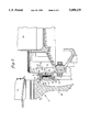
- FIG. 2 shows a diagrammatic sectional view of a turbine disc and blade and a stationary vane.
- a gas turbine engine may be described as comprising a low pressure compressor 10, a high pressure compressor 12, a combustor section 14, a high pressure turbine 16, and a low pressure turbine 18.
- Gases compressed in the compressor sections 10,12 are mixed with fuel and burned in the combustor section 14.
- the resultant gases at a higher temperature and pressure, then enter the turbine sections 16,18 and create pressure regions within the turbine sections 16,18.
- To optimize the work done by the engine it is necessary to position seals at specific points in the compressor sections 10,12 and turbine sections 16,18 to maintain discrete pressure zones.
- each turbine disc 20 includes a body having a web 28 extending radially outward, a head 30 formed at the radial extreme of the web 28, and a land 31 extending axially out from the head 30.
- a brush seal 32 seals the passage between a stationary vane 24 and a rotating turbine disc 20.
- the brush seal 32 comprises a seal element 34 and a seal ring 36.
- the seal element 34 includes a facing plate 38, a backing plate 40, and a plurality of bristles 42.
- the bristles 42 are fixed between the two plates 38,40 by welding or other conventional means.
- a retaining ring 43 attaches the seal element 34 to a seal support ring 44, which in turn positions the seal element 34 in close proximity to the seal ring 36.
- the seal support ring 44 is attached to the stationary vane 24 by conventional means.
- the seal ring 36 comprises a body 46, a first shoulder 48, and a second shoulder 50.
- the body 46 includes an inner edge 52, an outer edge 54, and a sealing surface 56.
- the first shoulder 48 extends radially outward adjacent the inner edge 52 and the second shoulder 50 extends radially outward adjacent the outer edge 54.
- the outer diameter of the second shoulder 50 is greater than that of the first shoulder 48.
- a coating 58 having a hardness greater than that of the seal ring 36 is attached to the sealing surface 56.
- the land 31 includes a first relief 59 in the inner radial surface of the land 31 and a second relief 60 aligned in the outer axial surface of the land 31.
- the reliefs 59,60 provide space for the seal ring 36 to be cut away, and thereby removed, without damaging the land 31.
- a second set of reliefs (not shown) may be positioned 180° away to permit the seal ring to be removed in halves.
- Relief configurations other than that described heretofore may be used alternatively. Indeed, depending upon the application it may be advantageous to place the relief(s) in the seal ring 36 rather than the member to which it is attached. Conventional fasteners may also be used to secure the seal ring 36.
- Conventional fasteners may also be used to secure the seal ring 36.
- the turbine disc 20 is heated to thermally expand the inner diameter of the land 31.
- the seal ring 36 may be cooled to shrink the outer diameters of the seal ring 36.
- the seal ring 36 is then slid into place, or "received" within the turbine disc land 31.
- the seal ring 36 is held in place by a diametral interference fit between the land 31 and the seal ring 36.
- the first 48 and second 50 shoulders of the seal ring 36 which form a male and female pair with the land 31 after assembly, prevent the seal ring 36 from moving axially relative to the land 31.
- the seal ring 36 and the seal element 34 are axially aligned with one another.
Landscapes
- Engineering & Computer Science (AREA)
- Mechanical Engineering (AREA)
- General Engineering & Computer Science (AREA)
- Turbine Rotor Nozzle Sealing (AREA)
Abstract
Description
Claims (12)
Priority Applications (1)
| Application Number | Priority Date | Filing Date | Title |
|---|---|---|---|
| US08/336,890 US5498139A (en) | 1994-11-09 | 1994-11-09 | Brush seal |
Applications Claiming Priority (1)
| Application Number | Priority Date | Filing Date | Title |
|---|---|---|---|
| US08/336,890 US5498139A (en) | 1994-11-09 | 1994-11-09 | Brush seal |
Publications (1)
| Publication Number | Publication Date |
|---|---|
| US5498139A true US5498139A (en) | 1996-03-12 |
Family
ID=23318132
Family Applications (1)
| Application Number | Title | Priority Date | Filing Date |
|---|---|---|---|
| US08/336,890 Expired - Lifetime US5498139A (en) | 1994-11-09 | 1994-11-09 | Brush seal |
Country Status (1)
| Country | Link |
|---|---|
| US (1) | US5498139A (en) |
Cited By (20)
| Publication number | Priority date | Publication date | Assignee | Title |
|---|---|---|---|---|
| DE19806090A1 (en) * | 1997-02-18 | 1998-08-20 | Europ Gas Turbines Ltd | Brush seal and method of making a brush seal |
| US6019580A (en) * | 1998-02-23 | 2000-02-01 | Alliedsignal Inc. | Turbine blade attachment stress reduction rings |
| US6170831B1 (en) * | 1998-12-23 | 2001-01-09 | United Technologies Corporation | Axial brush seal for gas turbine engines |
| US6471472B1 (en) | 2000-05-03 | 2002-10-29 | Siemens Canada Limited | Turbomachine shroud fibrous tip seal |
| US20050194747A1 (en) * | 2004-01-28 | 2005-09-08 | Rolls-Royce Plc | Sealing arrangement |
| US20060267291A1 (en) * | 2005-05-25 | 2006-11-30 | Mark Addis | Brush seal assembly and method of assembling same |
| EP1471211A3 (en) * | 2003-04-25 | 2006-12-13 | Rolls-Royce Deutschland Ltd & Co KG | Sealing arrangement between stator blades and rotor of a high pressure turbine |
| US20070096398A1 (en) * | 2005-10-28 | 2007-05-03 | Miller Jonathan L | Mechanical face seal housing with spring wall |
| US20080008574A1 (en) * | 2006-07-07 | 2008-01-10 | Siemens Power Generation, Inc. | Leakage flow control and seal wear minimization system for a turbine engine |
| US20100183426A1 (en) * | 2009-01-19 | 2010-07-22 | George Liang | Fluidic rim seal system for turbine engines |
| US20100196139A1 (en) * | 2009-02-02 | 2010-08-05 | Beeck Alexander R | Leakage flow minimization system for a turbine engine |
| US20110049810A1 (en) * | 2009-08-31 | 2011-03-03 | Roger Ferryman | Brush Seal With Stress And Deflection Accommodating Membrane |
| US20170051621A1 (en) * | 2015-08-19 | 2017-02-23 | United Technologies Corporation | Non-contact seal assembly for rotational equipment |
| EP3173670A1 (en) * | 2015-11-24 | 2017-05-31 | MTU Aero Engines GmbH | Brush seal assembly for a fluid flow machine, mounting securing arrangement and fluid flow machine |
| US9677407B2 (en) | 2013-01-09 | 2017-06-13 | United Technologies Corporation | Rotor cover plate |
| US20170298739A1 (en) * | 2016-04-15 | 2017-10-19 | Siemens Energy, Inc. | Bolt On Seal Ring |
| US10458258B2 (en) | 2013-01-30 | 2019-10-29 | United Technologies Corporation | Double snapped cover plate for rotor disk |
| US10662797B2 (en) | 2018-04-05 | 2020-05-26 | Raytheon Technologies Corporation | Multi-plane brush seal |
| US11035470B2 (en) | 2018-04-05 | 2021-06-15 | Raytheon Technologies Corporation | Multi-plane brush seal |
| US12000296B2 (en) | 2022-02-22 | 2024-06-04 | General Electric Company | Seal for a rotor |
Citations (27)
| Publication number | Priority date | Publication date | Assignee | Title |
|---|---|---|---|---|
| GB257330A (en) * | 1925-05-26 | 1926-08-26 | Athol Wilfrid Clarke | Improvements in labyrinth gland packing |
| GB492954A (en) * | 1937-02-08 | 1938-09-29 | Siemens Ag | Improvements in or relating to shaft packings for the casings of electrical machinesor apparatus |
| US3345035A (en) * | 1965-04-30 | 1967-10-03 | Gen Motors Corp | Turbine wheel |
| US3356339A (en) * | 1966-12-12 | 1967-12-05 | Gen Motors Corp | Turbine rotor |
| USRE30206E (en) * | 1973-11-23 | 1980-02-05 | Rolls Royce (1971) Limited | Seals and method of manufacture thereof |
| GB1598926A (en) * | 1978-05-24 | 1981-09-23 | Rolls Royce | Brush seals |
| JPS595807A (en) * | 1982-07-01 | 1984-01-12 | Fuji Electric Co Ltd | Structure of turbine rotor gland |
| DE3431990A1 (en) * | 1984-08-31 | 1986-03-13 | Kaco Gmbh + Co, 7100 Heilbronn | Sleeve for seals, preferably for radial shaft-sealing rings |
| US4657482A (en) * | 1980-10-10 | 1987-04-14 | Rolls-Royce Plc | Air cooling systems for gas turbine engines |
| US4798481A (en) * | 1986-01-24 | 1989-01-17 | Ina Walzlager Schaeffler Kg | Rolling bearing slewing ring |
| US4884850A (en) * | 1988-08-30 | 1989-12-05 | Pratt & Whitney Canada, Inc. | Method and apparatus for manufacturing compliant brush seals |
| US5031922A (en) * | 1989-12-21 | 1991-07-16 | Allied-Signal Inc. | Bidirectional finger seal |
| US5090710A (en) * | 1987-05-29 | 1992-02-25 | Cross Manufacturing Company (1938) Limited | Brush seals |
| US5106104A (en) * | 1990-10-11 | 1992-04-21 | General Electric Company | Constant pressure drop multiple stage brush seal |
| US5114159A (en) * | 1991-08-05 | 1992-05-19 | United Technologies Corporation | Brush seal and damper |
| US5135237A (en) * | 1989-04-05 | 1992-08-04 | Cross Manufacturing Company (1938) Limited | Brush seal with asymmetrical elements |
| JPH04347066A (en) * | 1991-05-21 | 1992-12-02 | Toshiba Corp | Brush sealing device |
| US5176389A (en) * | 1991-02-21 | 1993-01-05 | United Technologies | Segmented brush seal |
| US5181728A (en) * | 1991-09-23 | 1993-01-26 | General Electric Company | Trenched brush seal |
| US5192084A (en) * | 1990-12-12 | 1993-03-09 | Rolls-Royce Plc | Brush seal arrangement |
| US5201530A (en) * | 1991-10-18 | 1993-04-13 | United Technologies Corporation | Multi-layered brush seal |
| US5265412A (en) * | 1992-07-28 | 1993-11-30 | General Electric Company | Self-accommodating brush seal for gas turbine combustor |
| US5308088A (en) * | 1992-08-20 | 1994-05-03 | General Electric Company | Brush seal with flexible backing plate |
| US5310319A (en) * | 1993-01-12 | 1994-05-10 | United Technologies Corporation | Free standing turbine disk sideplate assembly |
| US5318309A (en) * | 1992-05-11 | 1994-06-07 | General Electric Company | Brush seal |
| US5335920A (en) * | 1992-08-20 | 1994-08-09 | General Electric Company | Brush seal |
| US5363906A (en) * | 1990-05-11 | 1994-11-15 | Borowy William J | Air heater seals |
-
1994
- 1994-11-09 US US08/336,890 patent/US5498139A/en not_active Expired - Lifetime
Patent Citations (27)
| Publication number | Priority date | Publication date | Assignee | Title |
|---|---|---|---|---|
| GB257330A (en) * | 1925-05-26 | 1926-08-26 | Athol Wilfrid Clarke | Improvements in labyrinth gland packing |
| GB492954A (en) * | 1937-02-08 | 1938-09-29 | Siemens Ag | Improvements in or relating to shaft packings for the casings of electrical machinesor apparatus |
| US3345035A (en) * | 1965-04-30 | 1967-10-03 | Gen Motors Corp | Turbine wheel |
| US3356339A (en) * | 1966-12-12 | 1967-12-05 | Gen Motors Corp | Turbine rotor |
| USRE30206E (en) * | 1973-11-23 | 1980-02-05 | Rolls Royce (1971) Limited | Seals and method of manufacture thereof |
| GB1598926A (en) * | 1978-05-24 | 1981-09-23 | Rolls Royce | Brush seals |
| US4657482A (en) * | 1980-10-10 | 1987-04-14 | Rolls-Royce Plc | Air cooling systems for gas turbine engines |
| JPS595807A (en) * | 1982-07-01 | 1984-01-12 | Fuji Electric Co Ltd | Structure of turbine rotor gland |
| DE3431990A1 (en) * | 1984-08-31 | 1986-03-13 | Kaco Gmbh + Co, 7100 Heilbronn | Sleeve for seals, preferably for radial shaft-sealing rings |
| US4798481A (en) * | 1986-01-24 | 1989-01-17 | Ina Walzlager Schaeffler Kg | Rolling bearing slewing ring |
| US5090710A (en) * | 1987-05-29 | 1992-02-25 | Cross Manufacturing Company (1938) Limited | Brush seals |
| US4884850A (en) * | 1988-08-30 | 1989-12-05 | Pratt & Whitney Canada, Inc. | Method and apparatus for manufacturing compliant brush seals |
| US5135237A (en) * | 1989-04-05 | 1992-08-04 | Cross Manufacturing Company (1938) Limited | Brush seal with asymmetrical elements |
| US5031922A (en) * | 1989-12-21 | 1991-07-16 | Allied-Signal Inc. | Bidirectional finger seal |
| US5363906A (en) * | 1990-05-11 | 1994-11-15 | Borowy William J | Air heater seals |
| US5106104A (en) * | 1990-10-11 | 1992-04-21 | General Electric Company | Constant pressure drop multiple stage brush seal |
| US5192084A (en) * | 1990-12-12 | 1993-03-09 | Rolls-Royce Plc | Brush seal arrangement |
| US5176389A (en) * | 1991-02-21 | 1993-01-05 | United Technologies | Segmented brush seal |
| JPH04347066A (en) * | 1991-05-21 | 1992-12-02 | Toshiba Corp | Brush sealing device |
| US5114159A (en) * | 1991-08-05 | 1992-05-19 | United Technologies Corporation | Brush seal and damper |
| US5181728A (en) * | 1991-09-23 | 1993-01-26 | General Electric Company | Trenched brush seal |
| US5201530A (en) * | 1991-10-18 | 1993-04-13 | United Technologies Corporation | Multi-layered brush seal |
| US5318309A (en) * | 1992-05-11 | 1994-06-07 | General Electric Company | Brush seal |
| US5265412A (en) * | 1992-07-28 | 1993-11-30 | General Electric Company | Self-accommodating brush seal for gas turbine combustor |
| US5308088A (en) * | 1992-08-20 | 1994-05-03 | General Electric Company | Brush seal with flexible backing plate |
| US5335920A (en) * | 1992-08-20 | 1994-08-09 | General Electric Company | Brush seal |
| US5310319A (en) * | 1993-01-12 | 1994-05-10 | United Technologies Corporation | Free standing turbine disk sideplate assembly |
Non-Patent Citations (2)
| Title |
|---|
| "CR Seals Handbook", Jan. 1986, pp. 31-33. |
| CR Seals Handbook , Jan. 1986, pp. 31 33. * |
Cited By (28)
| Publication number | Priority date | Publication date | Assignee | Title |
|---|---|---|---|---|
| DE19806090A1 (en) * | 1997-02-18 | 1998-08-20 | Europ Gas Turbines Ltd | Brush seal and method of making a brush seal |
| US6079714A (en) * | 1997-02-18 | 2000-06-27 | European Gas Turbines Limited | Brush seal and method for the manufacture of a brush seal |
| US6019580A (en) * | 1998-02-23 | 2000-02-01 | Alliedsignal Inc. | Turbine blade attachment stress reduction rings |
| US6170831B1 (en) * | 1998-12-23 | 2001-01-09 | United Technologies Corporation | Axial brush seal for gas turbine engines |
| US6471472B1 (en) | 2000-05-03 | 2002-10-29 | Siemens Canada Limited | Turbomachine shroud fibrous tip seal |
| EP1471211A3 (en) * | 2003-04-25 | 2006-12-13 | Rolls-Royce Deutschland Ltd & Co KG | Sealing arrangement between stator blades and rotor of a high pressure turbine |
| US20050194747A1 (en) * | 2004-01-28 | 2005-09-08 | Rolls-Royce Plc | Sealing arrangement |
| US20060267291A1 (en) * | 2005-05-25 | 2006-11-30 | Mark Addis | Brush seal assembly and method of assembling same |
| US20070096398A1 (en) * | 2005-10-28 | 2007-05-03 | Miller Jonathan L | Mechanical face seal housing with spring wall |
| US8714557B2 (en) * | 2005-10-28 | 2014-05-06 | United Technologies Corporation | Mechanical face seal housing with spring wall |
| US20080008574A1 (en) * | 2006-07-07 | 2008-01-10 | Siemens Power Generation, Inc. | Leakage flow control and seal wear minimization system for a turbine engine |
| US7549835B2 (en) | 2006-07-07 | 2009-06-23 | Siemens Energy, Inc. | Leakage flow control and seal wear minimization system for a turbine engine |
| US8277177B2 (en) | 2009-01-19 | 2012-10-02 | Siemens Energy, Inc. | Fluidic rim seal system for turbine engines |
| US20100183426A1 (en) * | 2009-01-19 | 2010-07-22 | George Liang | Fluidic rim seal system for turbine engines |
| US20100196139A1 (en) * | 2009-02-02 | 2010-08-05 | Beeck Alexander R | Leakage flow minimization system for a turbine engine |
| US20110049810A1 (en) * | 2009-08-31 | 2011-03-03 | Roger Ferryman | Brush Seal With Stress And Deflection Accommodating Membrane |
| US8505923B2 (en) | 2009-08-31 | 2013-08-13 | Sealeze, A Unit of Jason, Inc. | Brush seal with stress and deflection accommodating membrane |
| US9677407B2 (en) | 2013-01-09 | 2017-06-13 | United Technologies Corporation | Rotor cover plate |
| US10458258B2 (en) | 2013-01-30 | 2019-10-29 | United Technologies Corporation | Double snapped cover plate for rotor disk |
| US20170051621A1 (en) * | 2015-08-19 | 2017-02-23 | United Technologies Corporation | Non-contact seal assembly for rotational equipment |
| US10107126B2 (en) * | 2015-08-19 | 2018-10-23 | United Technologies Corporation | Non-contact seal assembly for rotational equipment |
| US20190003327A1 (en) * | 2015-08-19 | 2019-01-03 | United Technologies Corporation | Non-contact seal assembly for rotational equipment |
| US10975715B2 (en) * | 2015-08-19 | 2021-04-13 | Raytheon Technologies Corporation | Non-contact seal assembly for rotational equipment |
| EP3173670A1 (en) * | 2015-11-24 | 2017-05-31 | MTU Aero Engines GmbH | Brush seal assembly for a fluid flow machine, mounting securing arrangement and fluid flow machine |
| US20170298739A1 (en) * | 2016-04-15 | 2017-10-19 | Siemens Energy, Inc. | Bolt On Seal Ring |
| US10662797B2 (en) | 2018-04-05 | 2020-05-26 | Raytheon Technologies Corporation | Multi-plane brush seal |
| US11035470B2 (en) | 2018-04-05 | 2021-06-15 | Raytheon Technologies Corporation | Multi-plane brush seal |
| US12000296B2 (en) | 2022-02-22 | 2024-06-04 | General Electric Company | Seal for a rotor |
Similar Documents
| Publication | Publication Date | Title |
|---|---|---|
| US5498139A (en) | Brush seal | |
| US11274567B2 (en) | Keystoned blade track | |
| US5609469A (en) | Rotor assembly shroud | |
| US5244345A (en) | Rotor | |
| US10281045B2 (en) | Apparatus and methods for sealing components in gas turbine engines | |
| US4505640A (en) | Seal means for a blade attachment slot of a rotor assembly | |
| US5154577A (en) | Flexible three-piece seal assembly | |
| US4676715A (en) | Turbine rings of gas turbine plant | |
| EP0725888B1 (en) | Mounting and sealing arrangement for a turbine shroud segment | |
| JP4208496B2 (en) | Arc segment, nozzle segment and seal assembly | |
| US4863345A (en) | Turbine blade shroud structure | |
| CA2775145C (en) | Seal arrangement for segmented gas turbine engine components | |
| US4555901A (en) | Combustion chamber construction | |
| US4820119A (en) | Inner turbine seal | |
| CA2397613C (en) | Split ring for tip clearance control | |
| US4626169A (en) | Seal means for a blade attachment slot of a rotor assembly | |
| US4439107A (en) | Rotor blade cooling air chamber | |
| US20040173975A1 (en) | Sealing arrangements | |
| JPH10506177A (en) | Brush seal with secure anti-rotation tab | |
| US4655683A (en) | Stator seal land structure | |
| US20230399982A1 (en) | Seal for an aircraft engine | |
| US11125097B2 (en) | Segmented ring for installation in a turbomachine | |
| US10975707B2 (en) | Turbomachine disc cover mounting arrangement | |
| US11008894B2 (en) | BOAS spring clip | |
| US11739845B2 (en) | Carbon face seal |
Legal Events
| Date | Code | Title | Description |
|---|---|---|---|
| AS | Assignment |
Owner name: UNITED TECHNOLOGIES CORPORATION, CONNECTICUT Free format text: ASSIGNMENT OF ASSIGNORS INTEREST;ASSIGNOR:WILLIAMS, CHRISTOPHER C.;REEL/FRAME:007228/0461 Effective date: 19941103 |
|
| STCF | Information on status: patent grant |
Free format text: PATENTED CASE |
|
| AS | Assignment |
Owner name: AIR FORCE, UNITED STATES, VIRGINIA Free format text: CONFIRMATORY LICENSE;ASSIGNOR:UNITED TECHNOLOGIES CORPORATION;REEL/FRAME:008843/0755 Effective date: 19950106 |
|
| FEPP | Fee payment procedure |
Free format text: PAYOR NUMBER ASSIGNED (ORIGINAL EVENT CODE: ASPN); ENTITY STATUS OF PATENT OWNER: LARGE ENTITY |
|
| FPAY | Fee payment |
Year of fee payment: 4 |
|
| FEPP | Fee payment procedure |
Free format text: PAYOR NUMBER ASSIGNED (ORIGINAL EVENT CODE: ASPN); ENTITY STATUS OF PATENT OWNER: LARGE ENTITY Free format text: PAYER NUMBER DE-ASSIGNED (ORIGINAL EVENT CODE: RMPN); ENTITY STATUS OF PATENT OWNER: LARGE ENTITY |
|
| FPAY | Fee payment |
Year of fee payment: 8 |
|
| FEPP | Fee payment procedure |
Free format text: PAYER NUMBER DE-ASSIGNED (ORIGINAL EVENT CODE: RMPN); ENTITY STATUS OF PATENT OWNER: LARGE ENTITY Free format text: PAYOR NUMBER ASSIGNED (ORIGINAL EVENT CODE: ASPN); ENTITY STATUS OF PATENT OWNER: LARGE ENTITY |
|
| FPAY | Fee payment |
Year of fee payment: 12 |