EP0533765B1 - Magnetische detektionsvorrichtung für ferromagnetische ankerminen - Google Patents
Magnetische detektionsvorrichtung für ferromagnetische ankerminen Download PDFInfo
- Publication number
- EP0533765B1 EP0533765B1 EP19910911037 EP91911037A EP0533765B1 EP 0533765 B1 EP0533765 B1 EP 0533765B1 EP 19910911037 EP19910911037 EP 19910911037 EP 91911037 A EP91911037 A EP 91911037A EP 0533765 B1 EP0533765 B1 EP 0533765B1
- Authority
- EP
- European Patent Office
- Prior art keywords
- mine
- acoustic
- magnetometer
- magnetic field
- detection
- Prior art date
- Legal status (The legal status is an assumption and is not a legal conclusion. Google has not performed a legal analysis and makes no representation as to the accuracy of the status listed.)
- Expired - Lifetime
Links
Images


Classifications
-
- F—MECHANICAL ENGINEERING; LIGHTING; HEATING; WEAPONS; BLASTING
- F42—AMMUNITION; BLASTING
- F42C—AMMUNITION FUZES; ARMING OR SAFETY MEANS THEREFOR
- F42C13/00—Proximity fuzes; Fuzes for remote detonation
- F42C13/08—Proximity fuzes; Fuzes for remote detonation operated by variations in magnetic field
-
- G—PHYSICS
- G01—MEASURING; TESTING
- G01V—GEOPHYSICS; GRAVITATIONAL MEASUREMENTS; DETECTING MASSES OR OBJECTS; TAGS
- G01V3/00—Electric or magnetic prospecting or detecting; Measuring magnetic field characteristics of the earth, e.g. declination, deviation
- G01V3/08—Electric or magnetic prospecting or detecting; Measuring magnetic field characteristics of the earth, e.g. declination, deviation operating with magnetic or electric fields produced or modified by objects or geological structures or by detecting devices
Definitions
- Bottom mines are mines stowed at the bottom of a sea or ocean and are therefore fixed.
- one of the objectives of the invention is to implement a magnetic detection device which can be mounted on a mobile support, such as for example a ferromagnetic mine.
- FIG. 6 is a simulation illustrating the implementation of the correction method of the invention.
- Trace 61 corresponds to the magnetic field measured by the sensor of a rope mine, in the absence of correction.
- the plot 64 of FIG. 6 represents the modulus of the corrected magnetic field obtained with the method of the invention.
- Curve 62 represents the variations in the modulus of the magnetic field measured by a triaxial magnetometer mounted on a wire mine, the effect of the permanent field having been eliminated.
- the module of B t at the output of the processing block 14, obtained in the absence of disturbance, has variations of less than 50 nT. These small variations make it possible to detect a modification 63 of the module of the magnetic field 3 created by a building, in particular a ship or submarine, passing near the mine 5, the amplitude of the modification 63 being greater than the "residual noise" 64.
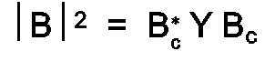
- the treatment process implemented thus has the advantage of allowing knowledge of M (in fact Y) without requiring the use of a mine attitude sensor.
Landscapes
- Engineering & Computer Science (AREA)
- Life Sciences & Earth Sciences (AREA)
- Physics & Mathematics (AREA)
- Remote Sensing (AREA)
- Geology (AREA)
- Environmental & Geological Engineering (AREA)
- Electromagnetism (AREA)
- General Life Sciences & Earth Sciences (AREA)
- General Physics & Mathematics (AREA)
- Geophysics (AREA)
- General Engineering & Computer Science (AREA)
- Geophysics And Detection Of Objects (AREA)
- Measuring Magnetic Variables (AREA)
Claims (6)

Applications Claiming Priority (2)
| Application Number | Priority Date | Filing Date | Title |
|---|---|---|---|
| FR9007511 | 1990-06-15 | ||
| FR9007511A FR2663428B1 (fr) | 1990-06-15 | 1990-06-15 | Dispositif de detection magnetique pour mines a orin ferromagnetiques. |
Publications (2)
| Publication Number | Publication Date |
|---|---|
| EP0533765A1 EP0533765A1 (de) | 1993-03-31 |
| EP0533765B1 true EP0533765B1 (de) | 1993-12-29 |
Family
ID=9397669
Family Applications (1)
| Application Number | Title | Priority Date | Filing Date |
|---|---|---|---|
| EP19910911037 Expired - Lifetime EP0533765B1 (de) | 1990-06-15 | 1991-06-04 | Magnetische detektionsvorrichtung für ferromagnetische ankerminen |
Country Status (4)
| Country | Link |
|---|---|
| EP (1) | EP0533765B1 (de) |
| DE (1) | DE69100900T2 (de) |
| FR (1) | FR2663428B1 (de) |
| WO (1) | WO1991020000A1 (de) |
Families Citing this family (3)
| Publication number | Priority date | Publication date | Assignee | Title |
|---|---|---|---|---|
| FR2931248B1 (fr) | 2008-05-14 | 2012-07-27 | Movea Sa | Systeme de mesure de champ magnetique comprenant un capteur triaxial de mesure de champ magnetique mobile conjointement avec un element porteur perturbant les mesures et procede associe |
| FR2950152B1 (fr) | 2009-09-15 | 2011-10-21 | Commissariat Energie Atomique | Procede et systeme de determination de l'activite d'une personne, support d'enregistrement pour ce procede |
| WO2011088519A1 (en) * | 2010-01-22 | 2011-07-28 | Minelab Electronics Pty Limited | Improved noise cancellation in a metal detector with a movable sensor head |
Family Cites Families (4)
| Publication number | Priority date | Publication date | Assignee | Title |
|---|---|---|---|---|
| US3967261A (en) * | 1974-10-10 | 1976-06-29 | Fudaley Solly L | Proximity sensor with simultaneously active intermixed sensor types |
| SE419380B (sv) * | 1977-09-27 | 1981-07-27 | Foerenade Fabriksverken | Sett att serskilja deplacerande mal fran en vattenyta |
| DE3045837C2 (de) * | 1980-12-05 | 1984-01-05 | Diehl GmbH & Co, 8500 Nürnberg | Zündschaltung für Sprengkörper |
| DE3804495A1 (de) * | 1987-12-19 | 1989-06-29 | Navsat Ag | Elektronische zuendeinrichtung fuer panzerabwehr-minen |
-
1990
- 1990-06-15 FR FR9007511A patent/FR2663428B1/fr not_active Expired - Lifetime
-
1991
- 1991-06-04 WO PCT/FR1991/000442 patent/WO1991020000A1/fr not_active Ceased
- 1991-06-04 EP EP19910911037 patent/EP0533765B1/de not_active Expired - Lifetime
- 1991-06-04 DE DE91911037T patent/DE69100900T2/de not_active Expired - Fee Related
Also Published As
| Publication number | Publication date |
|---|---|
| DE69100900D1 (de) | 1994-02-10 |
| FR2663428B1 (fr) | 1992-09-11 |
| EP0533765A1 (de) | 1993-03-31 |
| DE69100900T2 (de) | 1994-04-21 |
| FR2663428A1 (fr) | 1991-12-20 |
| WO1991020000A1 (fr) | 1991-12-26 |
Similar Documents
| Publication | Publication Date | Title |
|---|---|---|
| CN111123173B (zh) | 一种基于浮标的深远海磁力异常探测系统及探测方法 | |
| US12240574B2 (en) | Methods for monitoring windlass rotation | |
| EP0041892A1 (de) | Verfahren und Vorrichtungen zur Kompensierung magnetischer Störungen beim Messen eines magnetischen Kurses | |
| FR2886741A1 (fr) | Appareil et procede de determination de l'orientation d'un dispositif de guidage de flute marine | |
| CN107063198A (zh) | 一种船载自稳定云台测量系统及应用方法 | |
| CA3022175A1 (fr) | Self-calibrating and autonomous magnetic observatory | |
| CN112698412B (zh) | 基于磁浮标的轴频磁异常信号处理方法 | |
| EP0026706B1 (de) | Vorrichtung und Apparat zum Bestimmen der Richtungsparameter eines kontinuierlich untersuchten Bohrloches | |
| FR2587969A1 (fr) | Dispositif de desaimantation, notamment pour batiments navals | |
| CN121164991B (zh) | 一种基于金刚石nv色心的海洋磁场传感器的检测方法 | |
| RU2276388C1 (ru) | Морская автономная донная сейсмическая станция | |
| EP0011522A1 (de) | Vorrichtung zur Positionierung eines beweglichen Körpers mittels eines magnetischen Feldes | |
| EP0685387B1 (de) | Wasserfahrzeug für die Erkundung eines Ortes, insbesondere für Tiefenpeilungen | |
| EP1971882B1 (de) | Geophysikalisches messgerät zur erforschung von natürlichen bodenressourcen im wasser | |
| EP0597014B1 (de) | Tragbare station zur messung und regelung der magnetischen unterschrift eines wasserfahrzeuges | |
| FR2663428A1 (fr) | Dispositif de detection magnetique pour mines a orin ferromagnetiques. | |
| CN113703059A (zh) | 一种针对水际铁磁性目标集群的远距离磁探方法 | |
| EP0133408A1 (de) | Anlage zur Fahrwegbestimmung eines Marineschiffes | |
| Khalil et al. | Wave heave sensor verification in dry conditions with optoelectronic reference | |
| KR101019042B1 (ko) | 선박의 위치 측정 방법 및 그 장치 | |
| Li et al. | Vertical array signal recovery method based on normalized virtual time reversal mirror | |
| EP0210087A1 (de) | Verfahren und Anordnung zur induzierten Magnetisationsmessung in einem Seefahrtbauwerk | |
| FR2704065A1 (fr) | Dispositif de mesure de la signature magnétique d'un bâtiment naval et son application au réglage de l'immunisation magnétique. | |
| FR3043791A1 (de) | ||
| WO2021104986A1 (fr) | Procede de surveillance d'une zone maritime |
Legal Events
| Date | Code | Title | Description |
|---|---|---|---|
| PUAI | Public reference made under article 153(3) epc to a published international application that has entered the european phase |
Free format text: ORIGINAL CODE: 0009012 |
|
| 17P | Request for examination filed |
Effective date: 19921127 |
|
| AK | Designated contracting states |
Kind code of ref document: A1 Designated state(s): DE GB IT SE |
|
| 17Q | First examination report despatched |
Effective date: 19930524 |
|
| GRAA | (expected) grant |
Free format text: ORIGINAL CODE: 0009210 |
|
| STAA | Information on the status of an ep patent application or granted ep patent |
Free format text: STATUS: THE PATENT HAS BEEN GRANTED |
|
| AK | Designated contracting states |
Kind code of ref document: B1 Designated state(s): DE GB IT SE |
|
| ITF | It: translation for a ep patent filed | ||
| REF | Corresponds to: |
Ref document number: 69100900 Country of ref document: DE Date of ref document: 19940210 |
|
| RAP2 | Party data changed (patent owner data changed or rights of a patent transferred) |
Owner name: THOMSON-CSF |
|
| GBT | Gb: translation of ep patent filed (gb section 77(6)(a)/1977) |
Effective date: 19940307 |
|
| PLBI | Opposition filed |
Free format text: ORIGINAL CODE: 0009260 |
|
| 26 | Opposition filed |
Opponent name: SA MARINE AB Effective date: 19940929 |
|
| EAL | Se: european patent in force in sweden |
Ref document number: 91911037.9 |
|
| PGFP | Annual fee paid to national office [announced via postgrant information from national office to epo] |
Ref country code: DE Payment date: 19990512 Year of fee payment: 9 |
|
| PGFP | Annual fee paid to national office [announced via postgrant information from national office to epo] |
Ref country code: SE Payment date: 19990514 Year of fee payment: 9 |
|
| PGFP | Annual fee paid to national office [announced via postgrant information from national office to epo] |
Ref country code: GB Payment date: 19990520 Year of fee payment: 9 |
|
| PG25 | Lapsed in a contracting state [announced via postgrant information from national office to epo] |
Ref country code: GB Free format text: LAPSE BECAUSE OF NON-PAYMENT OF DUE FEES Effective date: 20000604 |
|
| PG25 | Lapsed in a contracting state [announced via postgrant information from national office to epo] |
Ref country code: SE Free format text: LAPSE BECAUSE OF NON-PAYMENT OF DUE FEES Effective date: 20000605 |
|
| GBPC | Gb: european patent ceased through non-payment of renewal fee |
Effective date: 20000604 |
|
| EUG | Se: european patent has lapsed |
Ref document number: 91911037.9 |
|
| PG25 | Lapsed in a contracting state [announced via postgrant information from national office to epo] |
Ref country code: DE Free format text: LAPSE BECAUSE OF NON-PAYMENT OF DUE FEES Effective date: 20010403 |
|
| RAP2 | Party data changed (patent owner data changed or rights of a patent transferred) |
Owner name: THALES |
|
| PG25 | Lapsed in a contracting state [announced via postgrant information from national office to epo] |
Ref country code: IT Free format text: LAPSE BECAUSE OF NON-PAYMENT OF DUE FEES;WARNING: LAPSES OF ITALIAN PATENTS WITH EFFECTIVE DATE BEFORE 2007 MAY HAVE OCCURRED AT ANY TIME BEFORE 2007. THE CORRECT EFFECTIVE DATE MAY BE DIFFERENT FROM THE ONE RECORDED. Effective date: 20050604 |