EP0532018A1 - Machine for the realization of spiral-shaped, cylindrical or conical iron - Google Patents
Machine for the realization of spiral-shaped, cylindrical or conical iron Download PDFInfo
- Publication number
- EP0532018A1 EP0532018A1 EP92115554A EP92115554A EP0532018A1 EP 0532018 A1 EP0532018 A1 EP 0532018A1 EP 92115554 A EP92115554 A EP 92115554A EP 92115554 A EP92115554 A EP 92115554A EP 0532018 A1 EP0532018 A1 EP 0532018A1
- Authority
- EP
- European Patent Office
- Prior art keywords
- spiral
- machine
- bending
- realization
- shaped metal
- Prior art date
- Legal status (The legal status is an assumption and is not a legal conclusion. Google has not performed a legal analysis and makes no representation as to the accuracy of the status listed.)
- Granted
Links
Images

Classifications
-
- B—PERFORMING OPERATIONS; TRANSPORTING
- B21—MECHANICAL METAL-WORKING WITHOUT ESSENTIALLY REMOVING MATERIAL; PUNCHING METAL
- B21F—WORKING OR PROCESSING OF METAL WIRE
- B21F27/00—Making wire network, i.e. wire nets
- B21F27/12—Making special types or portions of network by methods or means specially adapted therefor
- B21F27/121—Making special types or portions of network by methods or means specially adapted therefor of tubular form, e.g. as reinforcements for pipes or pillars
- B21F27/122—Making special types or portions of network by methods or means specially adapted therefor of tubular form, e.g. as reinforcements for pipes or pillars by attaching a continuous stirrup to longitudinal wires
- B21F27/124—Making special types or portions of network by methods or means specially adapted therefor of tubular form, e.g. as reinforcements for pipes or pillars by attaching a continuous stirrup to longitudinal wires applied by rotation
Definitions
- the present invention patent consists of a machine that realizes metal spirals of variable dimensions and pitch, where the coils are formed around the longitudinal bars; this machine, therefore, allows a considerable saving of time and of energies for the operators.
- the machine is constituted in its main parts by a series of bending rollers, which generate the coils, of a roller positioned near the exist of the iron piece from the bending rollers, which has an inclined axis with relation to the bending plane and to the horizontal direction and brings the already bent iron both outwards and toward a second upper roller; this second upper roller is idle and is perpendicular to the bending plane.
- the position of the inclined roller and of the idle upper roller can vary according to the needs.
- the idle upper roller can translate vertically, so that it is possible to vary the diameter of the spiral, can translate frontally to adapt to the spiral pitch and can translate laterally for possible settings; the adjustement of this cylinder can be manual or electromechanical.
- Two long parallel cyclinders are positioned in front of the bending machine, slightly downward, perpendicularly to the iron bending plane. Between these cylinders there are mobile forks that support the reinforcement longitudinal bars.
- the first operation to begin the process is the positioning on the forks of the reinforcement longitudinal bars, that afterwards will be fixed longitudinally along the spiral; these forks are positioned between the two front parallel cylinders, that are long enough to support the spiral in its complete development.
- the forks are raised higher than the parallel cylinders, so that the forming spiral doesn't touch the bars during the rotation.
- the two parallel cylinders rotate in the same direction, thus making the feed of the spiral itself easier.
- a shear is positioned in correspondence of the exit of the iron from the second bending machine.
- the bending process is stopped.
- the shear is brought near the iron, in one of its points near the exit from the second bending machine and then the shear is operated, cutting the iron and separating the whole spiral just produced from the iron hank that has still to be bent.
- the rod supporting forks are lowered, so that it is possible to go on with the fixing of the longitudinal bars to the spiral.
- positioning forks On the machine, besides the forks that keep all the longitudinal bars inside the spiral, there is a second series of forks, called positioning forks, the upper part of which has an upper vertical notch slightly wider than the diameter of a single bar.
- the positioning forks are raised; thanks to their shape, these positioning forks raise only one longitudinal bar and from inside bring it near the upper part of the spiral.
- the bar can be welded to the spiral by the automatic welding machines.
- Each one of these automatic welding machines is mounted on a trolley running on one or more special rails, that are parallel to the cylinders that support the spiral.
- the torch of the welding machine is mounted on the trolley by means of some mobile arms that bring the torch near the welding point, take the torch away from the welding point and rotate it around the welding point. Also some feelers are mounted on the trolley: they locate the point on which the welding has to be made, that is, the contact point between the longitudinal bar and the spiral.
- the welding machine For each longitudinal bar raised by the positioning forks, the welding machine is brought near the spiral and the feelers are positioned on the longitudinal bar. After that, the trolley advances and the feelers travel on the longitudinal bar.
- feelers When the feelers locate the contact point between the longitudinal bar and a tract of the spiral, they stop the trolley and operate the successive approach of the welding machine torch, that carries out the welding at the corresponding point.
- the positioning forks are lowered and the whole spiral rotates on the cylinders for the required angle.
- the whole cycle is repeated, that is, the positioning forks are raised again to bring another longitudinal bar in contact with the spiral and the trolley with the welding machine slides again to weld the new bar to the spiral.
- Both the feelers and the torch of the welding machine are mounted on a adjustable structure positioned on the trolley, so that they can adapt to the different sizes of the reinforcements to be realized.
- the operation of the shear, of the positioning forks, of the trolleys, of the feelers and of the welding machines is controlled by a specific electric/electronic circuit.
- the overturning scythe-shaped parts rotate on a plane that is perpendicular to the longitudinal bars; hooks equipped with a catch are hinged on their free end, in order to avoid the uncontrolled sliding of the reinforcement along the hooks themselves.
- These hooks are hinged to the scythe-shaped parts, so that their rotation with respect to the scythe-shaped parts themselves can be limited; a catch near the pivot of each hook doesn't allow them to rotate in the direction opposite to the reinforcement lifting direction, past the approximately aligned position of the hook with the scythe-shaped part.
- the upper mobile cylinder is raised in such a way as not to interfere with the working.
- the inclined roller is coupled with a new series of bending rollers with a variable bending direction, depending on the spiral pitch. This way the spiral, after coming out of the bending machine, meets another series of rolls for the side bending.
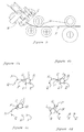
- Figure 1 shows the machine provided with equipment for bending irons (B), provided with a roller (C) that is inclined with respect to the coil (X) plane and inclined downward, that causes the lateral bending of the iron and directs the coil (X) itself toward the idle upper roller (D), that realizes the spiral diameter.
- the mobile idle upper roller (D) can be moved manually or electromechanically, it can also move upward or downward to vary the diameter and parallely to the bending plane to conform with the coil (X) pitch.
- the two front cylinders (E) support the spiral (X) in its formation and they both rotate in the same direction to help the feed of the forming spiral (X).
- Figure 2 shows an axonometric view of the machine, in which it is possible to notice the parallel cylinders (E), that support the spiral (X) for its whole length; at one end of the cylinders (E) there is the bending equipment (B).
- Figure 3 shows the bending unit of the machine, in case a very long-pitched spiral must be realized; it is possible to notice the bending rollers (B), the inclined roller (C) coupled with a second series of rollers (M), where the iron (X) is bent laterally.
- Figures 4a, 4b, 4c, 4d show in detail the movement of one overturning scythe-shaped part (N), equipped with hook (G), that rests on and then grasps one bar (L) of the metal structure (R), resting on the parallel cylinders (E) and that rotating around the pivot (Q) raises and extracts the metal structure (R) from the machine.
- Each hook (G) is provided with a catch that hinders the sliding of the structure along the hook (G) itself; besides, a tooth near the pivot (P) of each hook (G) doesn't allow the hook (G) itself to rotate in the direction opposite to that of the structure (R) lifting, past the approximately aligned position of the hook (G) with the scythe-shaped metal part (N).
- the upper part of the positioning forks (Fp) is rhomboid-shaped, with an upper vertical notch slightly wider than a longitudinal bar (B).
- these positioning forks (Fp) are raised, due to their form they take a single bar (B) from the group of longitudinal bars (B) to be welded and they raise it until the upper point inside the spiral (S), and then it has to be welded.
- a shear for example, an electropneumatic shear (A) is placed at the exit of the iron from the bending cylinders (B); it is controlled by an electromechanism connected with the machine, that provides for cutting the iron of the spiral (S), thus separating the spiral itself (S).
- a shear for example, an electropneumatic shear (A)
- A is placed at the exit of the iron from the bending cylinders (B); it is controlled by an electromechanism connected with the machine, that provides for cutting the iron of the spiral (S), thus separating the spiral itself (S).
- the feelers (T) and the torch (Z) of the welding machine are mounted on this trolley (l); on the edge of the trolley (I) there is also the welding machine (U).
- the feelers (T) that can be of any kind, preferably consist of a stem equipped with an electric contact that passes near the longitudinal bar (L) to be welded.
- the trolley provides for positioning the feeler (T) near this longitudinal bar (B) and for dragging it for the whole length of the bar itself.
- the torch (Z) is retracted and/or rotated and the trolley (I) is set into motion again until when the feeler (T) doesn't find another contact point between the bar (L) and the spiral (S).
Landscapes
- Engineering & Computer Science (AREA)
- Mechanical Engineering (AREA)
- Wire Processing (AREA)
- Iron Core Of Rotating Electric Machines (AREA)
- Springs (AREA)
- Diaphragms For Electromechanical Transducers (AREA)
- Reinforcement Elements For Buildings (AREA)
- Piles And Underground Anchors (AREA)
Abstract
Description
- In these days, for the production of metal spiral-shaped reinforcements bending machines are used to bend rods in continuous circles with constant diameter realizing a series of flanked coils; afterwards these coils are lengthened to realize a spiral of the desired length.
- This method involves a waste of time for the stretching out of the coils and also the trouble caused by the fact that, once the spiral has been produced, it is necessary to insert the longitudinal bars manually into it and then to fix them. The present invention patent consists of a machine that realizes metal spirals of variable dimensions and pitch, where the coils are formed around the longitudinal bars; this machine, therefore, allows a considerable saving of time and of energies for the operators. The machine is constituted in its main parts by a series of bending rollers, which generate the coils, of a roller positioned near the exist of the iron piece from the bending rollers, which has an inclined axis with relation to the bending plane and to the horizontal direction and brings the already bent iron both outwards and toward a second upper roller; this second upper roller is idle and is perpendicular to the bending plane. The position of the inclined roller and of the idle upper roller can vary according to the needs.
- The idle upper roller can translate vertically, so that it is possible to vary the diameter of the spiral, can translate frontally to adapt to the spiral pitch and can translate laterally for possible settings; the adjustement of this cylinder can be manual or electromechanical. Two long parallel cyclinders are positioned in front of the bending machine, slightly downward, perpendicularly to the iron bending plane. Between these cylinders there are mobile forks that support the reinforcement longitudinal bars.
- The first operation to begin the process is the positioning on the forks of the reinforcement longitudinal bars, that afterwards will be fixed longitudinally along the spiral; these forks are positioned between the two front parallel cylinders, that are long enough to support the spiral in its complete development.
- After having been loaded, the forks are raised higher than the parallel cylinders, so that the forming spiral doesn't touch the bars during the rotation.
- During the working, in order to help the unrolling of the spiral, the two parallel cylinders rotate in the same direction, thus making the feed of the spiral itself easier. A shear is positioned in correspondence of the exit of the iron from the second bending machine. When the desired length, that has been prefixed by means of special commands, is reached, the bending process is stopped. The shear is brought near the iron, in one of its points near the exit from the second bending machine and then the shear is operated, cutting the iron and separating the whole spiral just produced from the iron hank that has still to be bent. When the spiral has been completed the rod supporting forks are lowered, so that it is possible to go on with the fixing of the longitudinal bars to the spiral.
- On the machine, besides the forks that keep all the longitudinal bars inside the spiral, there is a second series of forks, called positioning forks, the upper part of which has an upper vertical notch slightly wider than the diameter of a single bar.
- Once the shear has cut the iron the positioning forks are raised; thanks to their shape, these positioning forks raise only one longitudinal bar and from inside bring it near the upper part of the spiral.
- At this pont the bar can be welded to the spiral by the automatic welding machines.
- Each one of these automatic welding machines is mounted on a trolley running on one or more special rails, that are parallel to the cylinders that support the spiral.
- The torch of the welding machine is mounted on the trolley by means of some mobile arms that bring the torch near the welding point, take the torch away from the welding point and rotate it around the welding point. Also some feelers are mounted on the trolley: they locate the point on which the welding has to be made, that is, the contact point between the longitudinal bar and the spiral.
- For each longitudinal bar raised by the positioning forks, the welding machine is brought near the spiral and the feelers are positioned on the longitudinal bar. After that, the trolley advances and the feelers travel on the longitudinal bar.
- When the feelers locate the contact point between the longitudinal bar and a tract of the spiral, they stop the trolley and operate the successive approach of the welding machine torch, that carries out the welding at the corresponding point.
- Finally the torch is retracted and the trolley is set into motion again until the feelers locate another contact point between the longitudinal bar and the spiral.
- Once the trolley has finished its run, the positioning forks are lowered and the whole spiral rotates on the cylinders for the required angle. The whole cycle is repeated, that is, the positioning forks are raised again to bring another longitudinal bar in contact with the spiral and the trolley with the welding machine slides again to weld the new bar to the spiral.
- Both the feelers and the torch of the welding machine are mounted on a adjustable structure positioned on the trolley, so that they can adapt to the different sizes of the reinforcements to be realized.
- In order to make the machine more efficient, it is possible to mount on the trolley two distinct feelers for the two sliding directions of the trolley, so that weldings can be made for every run of the trolley. Besides, it is possible to reduce the time required for the welding by using two or more welding machines that move contemporaneously along the spiral.
- The operation of the shear, of the positioning forks, of the trolleys, of the feelers and of the welding machines is controlled by a specific electric/electronic circuit.
- Once the fixing of the bars to the spiral has been completed, a series of overturning, scythe-shaped metal parts seize one of the longitudinal bars and provide for the extraction of the thus produced reinforcement.
- The overturning scythe-shaped parts rotate on a plane that is perpendicular to the longitudinal bars; hooks equipped with a catch are hinged on their free end, in order to avoid the uncontrolled sliding of the reinforcement along the hooks themselves. These hooks are hinged to the scythe-shaped parts, so that their rotation with respect to the scythe-shaped parts themselves can be limited; a catch near the pivot of each hook doesn't allow them to rotate in the direction opposite to the reinforcement lifting direction, past the approximately aligned position of the hook with the scythe-shaped part.
- If the constructor needs a very long-pitched spiral, the upper mobile cylinder is raised in such a way as not to interfere with the working. The inclined roller is coupled with a new series of bending rollers with a variable bending direction, depending on the spiral pitch. This way the spiral, after coming out of the bending machine, meets another series of rolls for the side bending.
- The following is just one example among many of the practical applications of the invention in question, illustrated in the attached tables.
- Figure 1 shows the machine provided with equipment for bending irons (B), provided with a roller (C) that is inclined with respect to the coil (X) plane and inclined downward, that causes the lateral bending of the iron and directs the coil (X) itself toward the idle upper roller (D), that realizes the spiral diameter. The mobile idle upper roller (D) can be moved manually or electromechanically, it can also move upward or downward to vary the diameter and parallely to the bending plane to conform with the coil (X) pitch.
- The two front cylinders (E) support the spiral (X) in its formation and they both rotate in the same direction to help the feed of the forming spiral (X).
- It is possible to sec one of the forks (F) that can be moved vertically and support the bars (L), that afterwards are fixed to the spiral (X) for its whole length.
- Figure 2 shows an axonometric view of the machine, in which it is possible to notice the parallel cylinders (E), that support the spiral (X) for its whole length; at one end of the cylinders (E) there is the bending equipment (B).
- Beside one of the cylinders (B) there are overturning scythe-shaped metal parts (N), that are equipped with hooks (G), so that they can grasp one of the longitudinal bars of the finished metal structure and extract it from the machine.
- Figure 3 shows the bending unit of the machine, in case a very long-pitched spiral must be realized; it is possible to notice the bending rollers (B), the inclined roller (C) coupled with a second series of rollers (M), where the iron (X) is bent laterally.
- Figures 4a, 4b, 4c, 4d show in detail the movement of one overturning scythe-shaped part (N), equipped with hook (G), that rests on and then grasps one bar (L) of the metal structure (R), resting on the parallel cylinders (E) and that rotating around the pivot (Q) raises and extracts the metal structure (R) from the machine.
- Each hook (G) is provided with a catch that hinders the sliding of the structure along the hook (G) itself; besides, a tooth near the pivot (P) of each hook (G) doesn't allow the hook (G) itself to rotate in the direction opposite to that of the structure (R) lifting, past the approximately aligned position of the hook (G) with the scythe-shaped metal part (N).
- In Figure 5 the forks (F) keep the longitudinal bars (B) at the centre of the spiral (S) while this is being formed.
- The upper part of the positioning forks (Fp) is rhomboid-shaped, with an upper vertical notch slightly wider than a longitudinal bar (B). When these positioning forks (Fp) are raised, due to their form they take a single bar (B) from the group of longitudinal bars (B) to be welded and they raise it until the upper point inside the spiral (S), and then it has to be welded.
- A shear, for example, an electropneumatic shear (A), is placed at the exit of the iron from the bending cylinders (B); it is controlled by an electromechanism connected with the machine, that provides for cutting the iron of the spiral (S), thus separating the spiral itself (S).
- Beside the machine there is a trolley (J) that slides on rails (Rt) parallel to the rollers (R) that support the spiral (S).
- The feelers (T) and the torch (Z) of the welding machine are mounted on this trolley (l); on the edge of the trolley (I) there is also the welding machine (U).
- In particular, the feelers (T), that can be of any kind, preferably consist of a stem equipped with an electric contact that passes near the longitudinal bar (L) to be welded.
- Once a longitudinal bar (L) has been raised by the positioning forks (Fp) until the inner upper part of the spiral (S), the trolley provides for positioning the feeler (T) near this longitudinal bar (B) and for dragging it for the whole length of the bar itself.
- Since the longitudinal bars (L) are positioned inside the spiral (S), when the feeler stem (T) reaches a transversal tract of the spiral (S) in contact with the longitudinal bar (L), a signal is activated to the electric/electronic control circuit, that stops the trolley (I) and brings the welding machine torch (Z) closer, to carry out the welding between the longitudinal bar (L) and the point of the spiral (S) that intersects this bar (L).
- Once the welding has been completed, the torch (Z) is retracted and/or rotated and the trolley (I) is set into motion again until when the feeler (T) doesn't find another contact point between the bar (L) and the spiral (S).
- When the whole longitudinal bar (L) has been covered the feeler is retracted, the positioning forks (Fp) are lowered, the whole spiral (S) is rotated by means of the rollers (E) on which it rosts and the positioning forks (Fp) are raised again to provide for a new welding cycle of another longitudinal bar (L).
- In order to improve the efficiency of the machine it is possible to plan two different feelers (T), placed at the sides of the welding machine torch (Z), in such a way as to carry out the weldings in both the sliding directions of the trolley (I), that is, to weld one bar (L) while the trolley is moving in one direction (l) and the following one with the return movement of the trolley (I).
- There is also the option to put two trolleys (I) on the same rails (Rt), each one of which operates on the spiral length (S); this way the welding times are halved.
Claims (9)
Applications Claiming Priority (4)
| Application Number | Priority Date | Filing Date | Title |
|---|---|---|---|
| ITPD910155 | 1991-09-11 | ||
| ITPD910155A IT1257979B (en) | 1991-09-11 | 1991-09-11 | Machine for production of spiral, cylindrical and/or conical reinforcement irons, for foundation piles or columns |
| ITPD920115 | 1992-06-26 | ||
| IT92PD000115A IT1278427B1 (en) | 1992-06-26 | 1992-06-26 | Machine for the production of spiralled iron reinforcements with automatic positioning and welding |
Publications (2)
| Publication Number | Publication Date |
|---|---|
| EP0532018A1 true EP0532018A1 (en) | 1993-03-17 |
| EP0532018B1 EP0532018B1 (en) | 1997-12-03 |
Family
ID=26331777
Family Applications (1)
| Application Number | Title | Priority Date | Filing Date |
|---|---|---|---|
| EP92115554A Expired - Lifetime EP0532018B1 (en) | 1991-09-11 | 1992-09-11 | Machine and method for the realization of spiral-shaped, cylindrical or conical iron |
Country Status (6)
| Country | Link |
|---|---|
| EP (1) | EP0532018B1 (en) |
| AT (1) | ATE160712T1 (en) |
| DE (1) | DE69223360T2 (en) |
| DK (1) | DK0532018T3 (en) |
| ES (1) | ES2109968T3 (en) |
| GR (1) | GR3026234T3 (en) |
Cited By (5)
| Publication number | Priority date | Publication date | Assignee | Title |
|---|---|---|---|---|
| WO2000066292A1 (en) * | 1999-04-29 | 2000-11-09 | Rom Group Limited | Helical winding machine |
| EP1243358A1 (en) * | 2001-03-19 | 2002-09-25 | M.E.P. Macchine Elettroniche Piegatrici S.p.A. | Device and method to complete reinforcement cages |
| WO2006119595A1 (en) | 2005-05-10 | 2006-11-16 | Maria Helena Vieira Maccaferri | System for serial line for cutting and bending of steel bars, rods and coils for manufacture of stirrups and longitudinal girders as well as assembly of steel armatures for beams, pillars, base plates, blocks, stakes, drums and other structural elements of reinforced concrete |
| CN107584053A (en) * | 2017-09-06 | 2018-01-16 | 中国建筑第八工程局有限公司 | Semi-automatic steel bar cage stirrup installation device |
| CN112958724A (en) * | 2021-03-03 | 2021-06-15 | 中国十七冶集团有限公司 | Simple bending method for non-standard stirrup |
Citations (5)
| Publication number | Priority date | Publication date | Assignee | Title |
|---|---|---|---|---|
| US2903553A (en) * | 1958-02-03 | 1959-09-08 | American Pipe & Constr Co | Continuous cage-making machine |
| CH481339A (en) * | 1968-08-16 | 1969-11-15 | Halmstads Jarnverks Ab | Reinforcement unit for concrete pipes, process for their manufacture and device for carrying out this process |
| FR2123116A1 (en) * | 1971-01-08 | 1972-09-08 | Commissariat Energie Atomique | BENDING-SPIRALING MACHINE FOR THE MANUFACTURE OF TUBE OR WIRE COILS |
| US3726461A (en) * | 1969-01-29 | 1973-04-10 | Nippon Concrete Ind Co Ltd | Apparatus for forming pc concrete pipe reinforcing |
| US3875977A (en) * | 1973-03-23 | 1975-04-08 | Universal Oil Prod Co | Method for making cylindrical screens |
-
1992
- 1992-09-11 ES ES92115554T patent/ES2109968T3/en not_active Expired - Lifetime
- 1992-09-11 DE DE69223360T patent/DE69223360T2/en not_active Expired - Lifetime
- 1992-09-11 EP EP92115554A patent/EP0532018B1/en not_active Expired - Lifetime
- 1992-09-11 AT AT92115554T patent/ATE160712T1/en active
- 1992-09-11 DK DK92115554T patent/DK0532018T3/en active
-
1998
- 1998-02-25 GR GR980400414T patent/GR3026234T3/en unknown
Patent Citations (5)
| Publication number | Priority date | Publication date | Assignee | Title |
|---|---|---|---|---|
| US2903553A (en) * | 1958-02-03 | 1959-09-08 | American Pipe & Constr Co | Continuous cage-making machine |
| CH481339A (en) * | 1968-08-16 | 1969-11-15 | Halmstads Jarnverks Ab | Reinforcement unit for concrete pipes, process for their manufacture and device for carrying out this process |
| US3726461A (en) * | 1969-01-29 | 1973-04-10 | Nippon Concrete Ind Co Ltd | Apparatus for forming pc concrete pipe reinforcing |
| FR2123116A1 (en) * | 1971-01-08 | 1972-09-08 | Commissariat Energie Atomique | BENDING-SPIRALING MACHINE FOR THE MANUFACTURE OF TUBE OR WIRE COILS |
| US3875977A (en) * | 1973-03-23 | 1975-04-08 | Universal Oil Prod Co | Method for making cylindrical screens |
Cited By (7)
| Publication number | Priority date | Publication date | Assignee | Title |
|---|---|---|---|---|
| WO2000066292A1 (en) * | 1999-04-29 | 2000-11-09 | Rom Group Limited | Helical winding machine |
| EP1243358A1 (en) * | 2001-03-19 | 2002-09-25 | M.E.P. Macchine Elettroniche Piegatrici S.p.A. | Device and method to complete reinforcement cages |
| WO2006119595A1 (en) | 2005-05-10 | 2006-11-16 | Maria Helena Vieira Maccaferri | System for serial line for cutting and bending of steel bars, rods and coils for manufacture of stirrups and longitudinal girders as well as assembly of steel armatures for beams, pillars, base plates, blocks, stakes, drums and other structural elements of reinforced concrete |
| CN107584053A (en) * | 2017-09-06 | 2018-01-16 | 中国建筑第八工程局有限公司 | Semi-automatic steel bar cage stirrup installation device |
| CN107584053B (en) * | 2017-09-06 | 2023-05-02 | 中国建筑第八工程局有限公司 | Semi-automatic steel reinforcement cage stirrup installation device |
| CN112958724A (en) * | 2021-03-03 | 2021-06-15 | 中国十七冶集团有限公司 | Simple bending method for non-standard stirrup |
| CN112958724B (en) * | 2021-03-03 | 2022-07-29 | 中国十七冶集团有限公司 | Simple bending method for non-standard stirrup |
Also Published As
| Publication number | Publication date |
|---|---|
| DE69223360T2 (en) | 1998-03-26 |
| DE69223360D1 (en) | 1998-01-15 |
| GR3026234T3 (en) | 1998-05-29 |
| EP0532018B1 (en) | 1997-12-03 |
| ES2109968T3 (en) | 1998-02-01 |
| DK0532018T3 (en) | 1998-08-10 |
| ATE160712T1 (en) | 1997-12-15 |
Similar Documents
| Publication | Publication Date | Title |
|---|---|---|
| CN110449540B (en) | Steel reinforcement cage welding forming machine | |
| JPH07252942A (en) | Metallic frame for reinforced concrete and method and equipment for forming said metallic frame | |
| EP0791416A1 (en) | Method for the production of metallic cages for reinforced concrete and relative device | |
| US5193378A (en) | Device for bending rod-like material to form concrete reinforcements | |
| US3893357A (en) | Process for cutting reinforcing steel bars for steel concrete and a bar cutting machine for effecting the process | |
| US4777706A (en) | Apparatus for manufacturing endless needled paper machine felts | |
| EP0532018A1 (en) | Machine for the realization of spiral-shaped, cylindrical or conical iron | |
| EP1378302B1 (en) | Method and apparatus for forming metal frames for reinforced concrete | |
| US5136867A (en) | Automatic frame bending machine for bending of steel rods or band steel | |
| US3405743A (en) | Reinforcing mat fabricating apparatus | |
| KR900000317B1 (en) | Method and machine for manufacturing three-dimensional metal structures | |
| US4072036A (en) | Bending machine | |
| US5316052A (en) | Machine for making wire lattice mats of welded longitudinal and cross wires with welded end loops | |
| US5009097A (en) | Plant or apparatus utilizing a universal straightening-bending machine | |
| EP2529857B1 (en) | Method and device for producing sheet-shaped reinforcement mats | |
| SU1804363A3 (en) | Method and plant for manufacture of two-layer welder lattice framework bent in form of bow | |
| JP2826829B2 (en) | Drawer | |
| CN211135343U (en) | Integral reinforcement cage welding machine | |
| KR100694226B1 (en) | Manufacturing Apparatus of Socket of Welding Wire Mesh for Concrete Bench flume | |
| US2810817A (en) | Wire mesh welding machine | |
| CN207615854U (en) | Welding machine of mesh for producing arc mesh sheet | |
| KR100419649B1 (en) | Apparatus for loading sleeve into tension reel | |
| EP0858846A2 (en) | Apparatus for cold bending of metal sheets for making elongated articles with predetermined profile | |
| EP0841110B1 (en) | Machine to assemble reinforcement stands for foundation piles | |
| US3561501A (en) | Crimping of wire reinforcing baskets |
Legal Events
| Date | Code | Title | Description |
|---|---|---|---|
| PUAI | Public reference made under article 153(3) epc to a published international application that has entered the european phase |
Free format text: ORIGINAL CODE: 0009012 |
|
| AK | Designated contracting states |
Kind code of ref document: A1 Designated state(s): AT BE CH DE DK ES FR GB GR LI LU NL PT SE |
|
| 17P | Request for examination filed |
Effective date: 19930917 |
|
| RAP1 | Party data changed (applicant data changed or rights of an application transferred) |
Owner name: HIGHSTONE VENTURE CAPITAL N.V. |
|
| 17Q | First examination report despatched |
Effective date: 19940805 |
|
| GRAG | Despatch of communication of intention to grant |
Free format text: ORIGINAL CODE: EPIDOS AGRA |
|
| GRAH | Despatch of communication of intention to grant a patent |
Free format text: ORIGINAL CODE: EPIDOS IGRA |
|
| GRAH | Despatch of communication of intention to grant a patent |
Free format text: ORIGINAL CODE: EPIDOS IGRA |
|
| GRAA | (expected) grant |
Free format text: ORIGINAL CODE: 0009210 |
|
| AK | Designated contracting states |
Kind code of ref document: B1 Designated state(s): AT BE CH DE DK ES FR GB GR LI LU NL PT SE |
|
| REF | Corresponds to: |
Ref document number: 160712 Country of ref document: AT Date of ref document: 19971215 Kind code of ref document: T |
|
| REG | Reference to a national code |
Ref country code: CH Ref legal event code: NV Representative=s name: ARNOLD & SIEDSMA AG Ref country code: CH Ref legal event code: EP |
|
| REF | Corresponds to: |
Ref document number: 69223360 Country of ref document: DE Date of ref document: 19980115 |
|
| ET | Fr: translation filed | ||
| REG | Reference to a national code |
Ref country code: ES Ref legal event code: FG2A Ref document number: 2109968 Country of ref document: ES Kind code of ref document: T3 |
|
| REG | Reference to a national code |
Ref country code: PT Ref legal event code: SC4A Free format text: AVAILABILITY OF NATIONAL TRANSLATION Effective date: 19980212 |
|
| REG | Reference to a national code |
Ref country code: DK Ref legal event code: T3 |
|
| PLBE | No opposition filed within time limit |
Free format text: ORIGINAL CODE: 0009261 |
|
| STAA | Information on the status of an ep patent application or granted ep patent |
Free format text: STATUS: NO OPPOSITION FILED WITHIN TIME LIMIT |
|
| 26N | No opposition filed | ||
| REG | Reference to a national code |
Ref country code: GB Ref legal event code: IF02 |
|
| PGFP | Annual fee paid to national office [announced via postgrant information from national office to epo] |
Ref country code: LU Payment date: 20110926 Year of fee payment: 20 Ref country code: CH Payment date: 20110928 Year of fee payment: 20 |
|
| PGFP | Annual fee paid to national office [announced via postgrant information from national office to epo] |
Ref country code: PT Payment date: 20110826 Year of fee payment: 20 Ref country code: DE Payment date: 20110927 Year of fee payment: 20 Ref country code: GR Payment date: 20110928 Year of fee payment: 20 Ref country code: SE Payment date: 20110930 Year of fee payment: 20 Ref country code: AT Payment date: 20110927 Year of fee payment: 20 Ref country code: GB Payment date: 20110929 Year of fee payment: 20 |
|
| PGFP | Annual fee paid to national office [announced via postgrant information from national office to epo] |
Ref country code: NL Payment date: 20111004 Year of fee payment: 20 Ref country code: BE Payment date: 20110929 Year of fee payment: 20 Ref country code: ES Payment date: 20110930 Year of fee payment: 20 Ref country code: DK Payment date: 20110930 Year of fee payment: 20 Ref country code: FR Payment date: 20111010 Year of fee payment: 20 |
|
| REG | Reference to a national code |
Ref country code: DE Ref legal event code: R071 Ref document number: 69223360 Country of ref document: DE |
|
| REG | Reference to a national code |
Ref country code: DE Ref legal event code: R071 Ref document number: 69223360 Country of ref document: DE |
|
| REG | Reference to a national code |
Ref country code: DK Ref legal event code: EUP |
|
| REG | Reference to a national code |
Ref country code: PT Ref legal event code: MM4A Free format text: MAXIMUM VALIDITY LIMIT REACHED Effective date: 20120911 |
|
| REG | Reference to a national code |
Ref country code: NL Ref legal event code: V4 Effective date: 20120911 |
|
| REG | Reference to a national code |
Ref country code: CH Ref legal event code: PL |
|
| BE20 | Be: patent expired |
Owner name: *HIGHSTONE VENTURE CAPITAL N.V. Effective date: 20120911 |
|
| REG | Reference to a national code |
Ref country code: GB Ref legal event code: PE20 Expiry date: 20120910 |
|
| REG | Reference to a national code |
Ref country code: AT Ref legal event code: MK07 Ref document number: 160712 Country of ref document: AT Kind code of ref document: T Effective date: 20120911 |
|
| REG | Reference to a national code |
Ref country code: SE Ref legal event code: EUG |
|
| PG25 | Lapsed in a contracting state [announced via postgrant information from national office to epo] |
Ref country code: GB Free format text: LAPSE BECAUSE OF EXPIRATION OF PROTECTION Effective date: 20120910 Ref country code: DE Free format text: LAPSE BECAUSE OF EXPIRATION OF PROTECTION Effective date: 20120912 |
|
| PG25 | Lapsed in a contracting state [announced via postgrant information from national office to epo] |
Ref country code: PT Free format text: LAPSE BECAUSE OF EXPIRATION OF PROTECTION Effective date: 20120918 |
|
| REG | Reference to a national code |
Ref country code: GR Ref legal event code: MA Ref document number: 980400414 Country of ref document: GR Effective date: 20120912 |
|
| REG | Reference to a national code |
Ref country code: ES Ref legal event code: FD2A Effective date: 20130715 |
|
| PG25 | Lapsed in a contracting state [announced via postgrant information from national office to epo] |
Ref country code: ES Free format text: LAPSE BECAUSE OF EXPIRATION OF PROTECTION Effective date: 20120912 |