EP1378302B1 - Method and apparatus for forming metal frames for reinforced concrete - Google Patents
Method and apparatus for forming metal frames for reinforced concrete Download PDFInfo
- Publication number
- EP1378302B1 EP1378302B1 EP03014545A EP03014545A EP1378302B1 EP 1378302 B1 EP1378302 B1 EP 1378302B1 EP 03014545 A EP03014545 A EP 03014545A EP 03014545 A EP03014545 A EP 03014545A EP 1378302 B1 EP1378302 B1 EP 1378302B1
- Authority
- EP
- European Patent Office
- Prior art keywords
- grip
- stirrup
- stirrups
- welding
- welding means
- Prior art date
- Legal status (The legal status is an assumption and is not a legal conclusion. Google has not performed a legal analysis and makes no representation as to the accuracy of the status listed.)
- Expired - Lifetime
Links
Images


Classifications
-
- B—PERFORMING OPERATIONS; TRANSPORTING
- B21—MECHANICAL METAL-WORKING WITHOUT ESSENTIALLY REMOVING MATERIAL; PUNCHING METAL
- B21F—WORKING OR PROCESSING OF METAL WIRE
- B21F27/00—Making wire network, i.e. wire nets
- B21F27/12—Making special types or portions of network by methods or means specially adapted therefor
- B21F27/121—Making special types or portions of network by methods or means specially adapted therefor of tubular form, e.g. as reinforcements for pipes or pillars
- B21F27/125—Making special types or portions of network by methods or means specially adapted therefor of tubular form, e.g. as reinforcements for pipes or pillars by attaching individual stirrups to longitudinal wires
-
- B—PERFORMING OPERATIONS; TRANSPORTING
- B21—MECHANICAL METAL-WORKING WITHOUT ESSENTIALLY REMOVING MATERIAL; PUNCHING METAL
- B21F—WORKING OR PROCESSING OF METAL WIRE
- B21F27/00—Making wire network, i.e. wire nets
Definitions
- the present invention relates to a method and an apparatus for forming metal frames for reinforced concrete.
- the reinforcement frame of reinforced concrete pillars and beams is commonly produced by using metal frames formed by longitudinal iron rods connected by suitably spaced transverse stirrups.
- the stirrups usually form a closed path, shaped for example like a quadrilateral, with overlapping ends.
- the longitudinal rods are inserted in the profile formed by the stirrups, for example at the corners of said profile.
- the method currently most widely used entails fitting the stirrups manually over the longitudinal rods, which are grouped and rested on suitable supports. After appropriately spacing the stirrups apart, and after tracing their position manually, some of the rods are tied to the upper portion of the stirrups. In the case, for example, of the stirrups having a quadrilateral profile, two longitudinal rods are tied at the corners of the upper horizontal side of the profile.
- a considerable execution time is required in particular both by the step for positioning the stirrups and the longitudinal rods of the frame and by the step for fixing said rods to the stirrups.
- Another method in use entails shaping panels made of electrowelded mesh.
- the longitudinal rods are normally added to the structure thus formed and are fixed in the manner described above.
- electrowelded mesh reduces the expenditure of labor for tying, but has the considerable limitation of being usable only for frames that have simple shapes and requires cutting the mesh panels to size, with a considerable waste of material and time.
- European patent EP 0667195 discloses a method for forming metal frames for reinforced concrete which entails first of all the provision of an intermediate frame constituted by stirrups that have a closed profile, are arranged on suitably spaced parallel planes, and are fixed to at least two throwaway longitudinal rods, which are welded externally to the stirrups. A plurality of rods is then coupled to said lattice, and said rods are inserted within the stirrups and tied to at least some of said stirrups with known methods.
- the apparatus that provides the cited solution is of the semiautomatic type and accordingly requires the use of labor.
- the stirrups produced by the stirrup bending machine must be picked up manually by the assigned personnel and first inserted one at a time between the auxiliary rods and then pushed between the clamps of the welding elements of the machine in order to form the lattice.
- the aim of the present invention is to solve the cited problems, by providing a method and an apparatus that allow to provide complete automation in the production of metal frames for reinforced concrete.
- an object of the present invention is to provide a method that allows to provide metal frames for reinforced concrete with a considerable reduction of production times.
- Another object of the invention is to provide an apparatus that allows to automate the production of metal frames for reinforced concrete with a structure that is simple in concept, safely reliable in operation, and versatile in use.
- a method for forming metal frames for reinforced concrete characterized in that it comprises the steps of:
- the reference numeral 1 generally designates the apparatus for forming metal frames for reinforced concrete according to the present invention.
- the apparatus 1 is suitable to be associated with a conventional stirrup bending machine 2; conveniently, the stirrup bending machine 2 is mounted on a truck 3 that can move on a portion of track 4 that is arranged in series to the apparatus 1.
- stirrup bending machine 2 has a working surface that is arranged vertically for the sake of convenience.
- the apparatus 1 has a chassis 5 that is provided with the working elements of the apparatus and is arranged in front of the stirrup bending machine 2.
- a longitudinally elongated platform 6 protrudes from the chassis 5 and forms a horizontal working surface.
- An intermediate lattice 10 for the final forming of a frame is meant to form on the working surface of the platform 6 and is obtained, as specified hereinafter, by joining longitudinal auxiliary rods 11 externally to a series of stirrups 12.
- the auxiliary rods 11 unwind from corresponding spools 7 which are arranged, preferably with a vertical axis, at the sides of the platform 6.
- the platform 6 has a first input portion 16 that is suitable to be connected to the chassis 5; the first portion 16 of the platform 6 is conveniently provided with two longitudinal slots 17 that are suitable to allow the passage of the movable supports 77, which rigidly follow the longitudinal movement of the clamps (see Figures 7 and 10).
- the chassis 5 and the platform 6 are adjustable in a vertical direction monolithically with each other, depending on the dimensions of the stirrups 12 being worked.
- the chassis 5 and the platform are supported by pantograph-type lifting elements 8 and 9, which are actuated synchronously by means of a motor 13 that turns suitable screw elements 14, 14a and 15, 15a (see in particular Figures 3 and 4).
- the chassis 5 is constituted by two lateral cross-members 18, which are connected at the base by two transverse longitudinal members 19.
- the cross-members 18 are suitable to be fixed, by means of screw elements, to corresponding lateral portions of the first lifting element 8, whose width is proportionate to the width of the chassis 5.
- Respective rail-type guides 20 are associated with the longitudinal members 19, and a plurality of trucks 21 and 22 can slide thereon; said trucks are mounted on wheels 23 and can be moved manually transversely to the line for forming the lattice 10. More precisely, the apparatus has two lateral trucks 21, which are mutually symmetrical, and a central truck 22.
- the trucks 21, 22 are constituted by respective frames, each mounted on three wheels 23 per side, arranged with suitably offset axes 24, which slide within the rails 20.
- the trucks 21 and 22 are further provided so that they can be blocked in the working position by way of respective braking elements 25 that are actuated pneumatically.
- the trucks 21 and 22 support respective working heads 31 and 32 that are meant to weld the auxiliary rods 11 to the stirrups 12 and to draw the lattice 10 being formed.
- the auxiliary rods 11 that unwind from the spools 7 are diverted on rollers 26, which are mounted so that they can rotate on vertical rods 27 that are fixed at the cross-members 18 of the chassis 5, and said rods then engage respective straightening elements 28 that are moved into position by the trucks 21 and 22 and are constituted by a series of rollers that have a vertical axis.
- Corresponding portal-shaped frameworks 30 rise from the lateral trucks 21, and the lateral working heads 31 can move thereon in a vertical direction.
- the lateral working heads 31 are mounted respectively on a cross-member 34, which is provided at its ends with sliders 35 that can slide on vertical guides 36 formed by the posts 37 of the portal-shaped framework 30.
- the upper cross-member 38 of the portal-shaped framework 30 supports a motor element 39, which actuates a threaded shaft 40, that is rotatable about a vertical axis and is arranged so as to engage a female thread element 41 that is associated with the cross-member 34 ( Figure 6).
- the lateral working heads 31 can be moved in a transverse direction by way of the movement of the corresponding trucks 21 and that the height of their position can be adjusted independently by way of the corresponding motor elements 39; the lateral working heads 31, moreover, can be rotated angularly at respective pivots 29.
- the central working head 32 is instead fixed on the corresponding truck 22, and therefore its position can be adjusted only in a transverse direction.
- the height of the central working head 32 is actually adjusted by way of the pantograph-type lifting elements 8 and 9, which move the chassis 5 and the platform 6 in a vertical direction, depending on the dimensions of the stirrups 12 being worked.
- stirrups 12 have a fixed reference position on the apparatus, defined in practice by the cutting elements 90 of the stirrup bending machine 2, at the upper arm of the stirrups 12, while the position of the lower arm is determined accordingly by the dimensions of the stirrups 12 and is obtained through the adjustment of the height of the chassis 5 and of the platform 6 by virtue of the pantograph-type lifting elements 8 and 9.
- the pantograph-like lifting elements 8 and 9 are adapted to move the chassis 5 and the platform 6 to a maximum lifting position, shown schematically by the dashed line 6a in Figure 1, which in practice coincides with said fixed reference position defined by the cutting elements 90 of the stirrup bending machine 2.
- the apparatus actually allows to work stirrups constituted by linear bar segments, in order to provide with the longitudinal auxiliary rods 11 a mesh-like lattice or stirrups formed toward the upper part of the machine, i.e., with the reference of the zero plane in the lower part of the stirrup instead of in the upper region.
- the central truck 22 in turn supports a gearmotor 42, which is suitable to actuate, by way of a suitable gear 43, a transverse splined shaft 44, which is supported so that it can rotate about a horizontal axis between the cross-members 18 of the chassis 5.
- the horizontal splined shaft 44 is provided so as to transmit motion, by way of a corresponding bevel gear pair 45, to respective vertical shafts 46, which are supported rotatably by the lateral trucks 21 at a box 47; the vertical shafts 46 turn a gear 48, which is meant to actuate, as specified hereinafter, traction means that are associated with said lateral working heads 31.
- An additional gear 49 is furthermore mounted on the horizontal splined shaft 44 and is meant to actuate, in turn, traction means that are associated with the central working head 32.
- the position of the working heads 31 and 32 is adjusted by first moving said working heads 31 and 32 simultaneously in a vertical direction; once the correct position intended for the central working head 32 is reached, the lateral working heads 31 provided with individual adjustment movements are adjusted with respect to said central working head.
- Each one of the working heads 31 and 32 is provided with respective means 50 for gripping and welding the auxiliary rods 11 and the stirrups 12 that are designed to form said intermediate lattice 10.
- said grip and welding means 50 have a grip element 51, which is constituted by a beak 52 that is rigidly coupled to the stem 53 of a linear actuator 54 ( Figure 13).
- the actuator 54 is fixed to a bracket 55 that is rigidly coupled to a stem 56 that is guided so that it can slide, in contrast with elastic means 57, through a sliding block 58, which is in turn rigidly coupled to the stem 60 of a second linear actuator 61, along an axis that is parallel to the axis of the first actuator 54.
- the second actuator 61 is supported by a brace 63, which is provided with a pair of stems 64 for guiding the sliding block 58.
- the bracket 55 is provided with a housing 65 for protecting the beak 52.
- the bracket 55 is furthermore provided with a protruding roller 59, which is suitable to act as a locator on the front surface of the stirrup bending machine 2.
- the brace 63 is fixed to the end of a pair of horizontal guiding shafts 66, which pass slidingly through a body 67. At the opposite end, the shafts 66 are fixed by means of a plate 68 to the stem 69 of a double-stroke actuator 70, which in practice is constituted by a first long-stroke jack 71 and by a second short-stroke jack 72, which are arranged in series.
- the body 67 is fixed, by means of a flange 73, to a box-like enclosure 74, which acts as a support for a transformer element 75.
- the enclosure 74 has a rack 76 rigidly coupled below it; said rack is suitable to mesh with a corresponding gear 48 and 49, which is turned by the gearmotor 42 by means of the splined shaft 44.
- the illustrated case which relates to the central working head 32, shows the coupling of the rack 76 to the gear 49 mounted at the central truck 22.
- welding means 80 which are supported in a cantilevered fashion and are constituted by movable welding units 81, which cooperate with fixed welding units 82 (see in particular Figures 22 and 23).
- the movable welding units 81 are supported by an arm 83, which can be actuated by a linear actuator 84.
- the fixed welding units 82 are mounted on a body 85, which is supported elastically on stems 86 in contrast with elastic means 87.
- the method for forming metal frames for reinforced concrete by means of the described apparatus mainly entails forming a lattice 10 that is constituted by a plurality of stirrups 12 that have a closed or open profile, are arranged on suitably spaced parallel planes, and are mutually connected by one or more longitudinal auxiliary rods 11 welded to the outside of said stirrups 12.
- the stirrups 12 form a substantially rectangular profile and are mutually connected by means of three auxiliary rods 11, which are arranged respectively on the lateral portions and on the lower portion of the stirrups 12 (see Figure 9).
- the stirrups 12 can of course have any kind of shape, even a very complex one.
- the auxiliary rods 11 are constituted by rods that have any cross-section, for example a narrow one, which is not defined by the designer of the structure. Preferably, the auxiliary rods 11 are thinner than the stirrups. Clearly, in addition to having a circular cross-section, the auxiliary rods 11 can also have a flattened shape or other similar shapes. It is further possible to provide on the auxiliary rods 11 suitable shaped portions or distinctive elements of any kind, for example a series of suitably spaced recesses.
- auxiliary rods 11 that unwind from the spools 7 engage respectively the straightening elements 28, which are carried in an adjustable position by the trucks 21 and 22 of the apparatus, and are then welded by the corresponding working heads 31 and 32 to the stirrups 12 provided by the stirrup bending machine 2.
- the stirrups 12 are picked up automatically on the stirrup bending machine 2, which for this purpose is arranged, so that its working surface is preferably vertical, in front of the described apparatus, at an input region E thereof ( Figure 1).
- the apparatus grips the stirrup 12 to be picked up by means of the grip elements 51 of the working heads 31 and 32 before the cutting of said stirrup 12 from the material in bar or coil form from which it is obtained by bending.
- the grip elements 51 are moved by the double-stroke actuator 70 into a grip position that is formed by the abutment of the roller 59 on the stirrup bending machine 2, with the beak 52 open on a corresponding portion of the stirrup 12 ( Figure 14).
- stirrup 12 After the stirrup 12 has been gripped by the grip elements 51, said stirrup 12 is cut by the conventional cutting elements 90 of the stirrup bending machine 2 ( Figure 5).
- the stirrup 12 gripped by the grip elements 51 is then moved in a longitudinal direction by virtue of the actuation of the corresponding double-stroke actuators 70, until a preset working position (Figure 16) is reached.
- the welding means 80 preset in said working position, are activated.
- the movable welding units 81 are lifted by the actuator 84 ( Figure 17), followed by a suitable retraction stroke of the grip elements 51 under the control of the second short-stroke jack 72 of the actuator 70, in order to place the stirrup 12 at said movable welding units 81 ( Figure 18).
- This is followed by the fastening of said stirrup 12 between the welding units 81 and 82, for example of the resistance type, and by the release of the stirrup 12 on the part of the grip elements 51, in order to weld externally to said stirrup the auxiliary rod 11 simultaneously fed in a longitudinal direction (Figure 19).
- stirrups 12 is welded at the chosen distance to the auxiliary rods 11 so as to form the lattice 10.
- the mutual distance between the stirrups 12 is not necessarily constant, but can be changed along the longitudinal extension of the lattice 10, according to the various requirements.
- auxiliary rods 11 are preferably narrower than the stirrups 12, said stirrups are not affected by the welding step that instead causes the local melting only of the auxiliary rods 11.
- the resulting lattice 10 can be used to provide the metallic frame, in particular by coupling suitable rods 12 inside the stirrups 12. More specifically, the rods used to form the frames are constituted by longitudinal supporting bars, whose characteristics are determined by the designer of the structure according to calculations in accordance with the applicable standards. The supporting bars are fixed to at least some of the stirrups 12 of the lattice 10, for example by means of conventional bindings.
- stirrups 12 are instead already fixed and spaced by virtue of the welding with the auxiliary rods 11 of the lattice 10 and therefore bindings are needed only to keep the longitudinal bars in position.
- the method and the apparatus according to the invention allow to provide complete automation in the production of intermediate lattices for forming metal frames for reinforced concrete, eliminating the need for the operator to pick up the stirrups from the stirrup bending machine, carry them and insert them manually and individually in the assembly apparatus by means of a second operator.
- the apparatus according to the invention is free at the front input region E, so that the stirrups 12 can be picked up at the front.
- the apparatus can therefore adapt to any kind of stirrup bending machine without requiring structural modifications.
- the straightening elements 28 supported by the trucks 21 and 22 are arranged in an oblique position that converges toward the output with respect to the lattice 10 being formed, so as to form, with the corresponding auxiliary rods 11, a sort of funnel.
- This allows to have enough free space to introduce the stirrup 12 at the front, without interfering with said straightening units 28 and without the risk of any scraping of the stirrup 12 against the rods 11.
- the auxiliary rods 11 in fact assume a path that is substantially tangent to the lattice 10 only after they have been welded.
- stirrups 12 are loaded manually or by way of automatic loading means of a different type, for particular production requirements.
- One prerogative of the method and apparatus according to the invention is constituted by the fact that the advancement of the lattice 10 being formed is provided by the welding elements 80 that weld the stirrups 12 to the auxiliary rods 11. It is therefore possible to weld the stirrups 12, at least partially, during said step for the advancement of the lattice 10, with an overlap of the two steps that obviously leads to a substantial reduction in downtimes and therefore to a significant time saving.
- auxiliary rods 11 can be joined to the stirrups 12 through any type of coupling, particularly through any welding method.
- the rods 11 can be located on any side of the stirrups 12, and there may be even more than one rod per side, according to the requirements.
- the method for moving the frame being formed may also be any, by traction or pushing, for example by using traction wheels integrated in the straightening unit.
- the materials used may be any according to requirements.
Abstract
Description
- The present invention relates to a method and an apparatus for forming metal frames for reinforced concrete.
- It is known that the reinforcement frame of reinforced concrete pillars and beams is commonly produced by using metal frames formed by longitudinal iron rods connected by suitably spaced transverse stirrups. The stirrups usually form a closed path, shaped for example like a quadrilateral, with overlapping ends. The longitudinal rods are inserted in the profile formed by the stirrups, for example at the corners of said profile.
- In order to form such metal frames, the method currently most widely used entails fitting the stirrups manually over the longitudinal rods, which are grouped and rested on suitable supports. After appropriately spacing the stirrups apart, and after tracing their position manually, some of the rods are tied to the upper portion of the stirrups. In the case, for example, of the stirrups having a quadrilateral profile, two longitudinal rods are tied at the corners of the upper horizontal side of the profile.
- Then the remaining longitudinal rods are inserted on the lower portion of the stirrups and said rods also are tied to the stirrups. Additional longitudinal rods can of course be coupled, according to the requirements, to the metallic frame thus formed, for example in intermediate positions on the vertical portions.
- It is quite evident that this constructive solution entails a considerable expenditure of time and high labor costs in addition to limited productivity. All these steps are in fact performed manually by assigned personnel.
- A considerable execution time is required in particular both by the step for positioning the stirrups and the longitudinal rods of the frame and by the step for fixing said rods to the stirrups.
- Another method in use entails shaping panels made of electrowelded mesh. The longitudinal rods are normally added to the structure thus formed and are fixed in the manner described above. The use of electrowelded mesh reduces the expenditure of labor for tying, but has the considerable limitation of being usable only for frames that have simple shapes and requires cutting the mesh panels to size, with a considerable waste of material and time.
- Devices for forming reinforcement frames by tying or welding structural rods to stirrups, are disclosed in documents WO-A-87/05544 and WO-A-85/05053.
- European patent EP 0667195, by the same Applicant, discloses a method for forming metal frames for reinforced concrete which entails first of all the provision of an intermediate frame constituted by stirrups that have a closed profile, are arranged on suitably spaced parallel planes, and are fixed to at least two throwaway longitudinal rods, which are welded externally to the stirrups. A plurality of rods is then coupled to said lattice, and said rods are inserted within the stirrups and tied to at least some of said stirrups with known methods.
- The advantage of this solution is constituted by the fact that the provision of the intermediate lattice avoids the need to fix all the longitudinal rods to all the stirrups, since it is sufficient to provide only a few bindings. This achieves a significant time saving in the overall production cycle.
- The apparatus that provides the cited solution is of the semiautomatic type and accordingly requires the use of labor. In particular, the stirrups produced by the stirrup bending machine must be picked up manually by the assigned personnel and first inserted one at a time between the auxiliary rods and then pushed between the clamps of the welding elements of the machine in order to form the lattice.
- This solution, moreover, entails relatively long downtimes during the formation of the intermediate lattice.
- The aim of the present invention is to solve the cited problems, by providing a method and an apparatus that allow to provide complete automation in the production of metal frames for reinforced concrete.
- Within this aim, an object of the present invention is to provide a method that allows to provide metal frames for reinforced concrete with a considerable reduction of production times.
- Another object of the invention is to provide an apparatus that allows to automate the production of metal frames for reinforced concrete with a structure that is simple in concept, safely reliable in operation, and versatile in use.
- This aim and these objects are achieved, according to the present invention, by a method for forming metal frames for reinforced concrete, characterized in that it comprises the steps of:
- (a). stopping the working cycle of a stirrup bending machine before cutting individual stirrups having a closed or open profile, so that said individual stirrups are arranged on a working surface of said stirrup bending machine that faces a front input region of an apparatus for forming metal frames that is arranged downstream of said stirrup bending machine;
- (b). gripping in succession a single stirrup arranged on said stirrup bending machine by way of grip and welding means that can move along a direction that is longitudinal with respect to said input region;
- (c) cutting said stirrup, gripped by said grip and welding means at said stirrup bending machine, from the source material;
- (d). fixing externally to each stirrup, retained by said grip and welding means, at least one longitudinal auxiliary rod;
- (e). performing, with suitable timing, the alternating movement of said grip and welding means in a forward position, by actuation of traction means that can move along said longitudinal direction, in order to produce the stepwise traction of said auxiliary rod and of said stirrups, during welding thereto performed by welding means that are associated with said grip and welding means, so as to form an intermediate lattice for the final production of a frame.
- The features of the invention will become better apparent from the detailed description of a preferred embodiment of the apparatus for forming metal frames for reinforced concrete, illustrated by way of non-limitative example in the accompanying drawings, wherein:
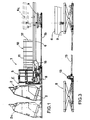
- Figure 1 is a general side view of the apparatus for forming metal frames for reinforced concrete according to the method of the invention;
- Figure 2 is a corresponding plan view thereof;
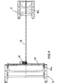
- Figure 3 is an enlarged-scale side view of lifting means of the apparatus;
- Figure 4 is a corresponding plan view of said means of the apparatus;
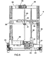
- Figure 5 is a general front view of the working heads of the apparatus;
- Figure 6 is a partially cutout sectional side view thereof;
- Figure 7 is a plan view thereof;
- Figure 8 is an enlarged-scale plan view of part of said working heads;
- Figure 9 is an enlarged-scale front view of said working heads;
- Figure 10 is a front view of a detail of a working head;
- Figure 11 is a general plan view of a working head;
- Figure 12 is a partial enlarged-scale view thereof;
- Figure 13 is a corresponding longitudinal sectional view thereof;
- Figure 14 is a side view of said working head;
- Figures 15, 16, 17, 18, 19, 20 and 21 are side views of said lateral head in successive operating steps of the apparatus;
- Figure 22 is a side view of welding means that are associated with said working head;
- Figure 23 is a corresponding front view thereof.
- With reference to the figures, the
reference numeral 1 generally designates the apparatus for forming metal frames for reinforced concrete according to the present invention. Theapparatus 1 is suitable to be associated with a conventionalstirrup bending machine 2; conveniently, thestirrup bending machine 2 is mounted on a truck 3 that can move on a portion of track 4 that is arranged in series to theapparatus 1. - It should be noted that the
stirrup bending machine 2 has a working surface that is arranged vertically for the sake of convenience. - The
apparatus 1 has achassis 5 that is provided with the working elements of the apparatus and is arranged in front of thestirrup bending machine 2. A longitudinallyelongated platform 6 protrudes from thechassis 5 and forms a horizontal working surface. Anintermediate lattice 10 for the final forming of a frame is meant to form on the working surface of theplatform 6 and is obtained, as specified hereinafter, by joining longitudinalauxiliary rods 11 externally to a series ofstirrups 12. Theauxiliary rods 11 unwind fromcorresponding spools 7 which are arranged, preferably with a vertical axis, at the sides of theplatform 6. - The
platform 6 has afirst input portion 16 that is suitable to be connected to thechassis 5; thefirst portion 16 of theplatform 6 is conveniently provided with twolongitudinal slots 17 that are suitable to allow the passage of themovable supports 77, which rigidly follow the longitudinal movement of the clamps (see Figures 7 and 10). - The
chassis 5 and theplatform 6 are adjustable in a vertical direction monolithically with each other, depending on the dimensions of thestirrups 12 being worked. For this purpose, thechassis 5 and the platform are supported by pantograph-type lifting elements motor 13 that turnssuitable screw elements - The
chassis 5 is constituted by twolateral cross-members 18, which are connected at the base by two transverselongitudinal members 19. The cross-members 18 are suitable to be fixed, by means of screw elements, to corresponding lateral portions of thefirst lifting element 8, whose width is proportionate to the width of thechassis 5. - Respective rail-type guides 20 are associated with the
longitudinal members 19, and a plurality oftrucks wheels 23 and can be moved manually transversely to the line for forming thelattice 10. More precisely, the apparatus has twolateral trucks 21, which are mutually symmetrical, and acentral truck 22. - The
trucks wheels 23 per side, arranged with suitably offset axes 24, which slide within therails 20. Thetrucks respective braking elements 25 that are actuated pneumatically. - The
trucks auxiliary rods 11 to thestirrups 12 and to draw thelattice 10 being formed. Theauxiliary rods 11 that unwind from thespools 7 are diverted onrollers 26, which are mounted so that they can rotate onvertical rods 27 that are fixed at the cross-members 18 of thechassis 5, and said rods then engagerespective straightening elements 28 that are moved into position by thetrucks - Corresponding portal-shaped
frameworks 30 rise from thelateral trucks 21, and the lateral working heads 31 can move thereon in a vertical direction. - The lateral working heads 31 are mounted respectively on a cross-member 34, which is provided at its ends with
sliders 35 that can slide onvertical guides 36 formed by theposts 37 of the portal-shapedframework 30. Theupper cross-member 38 of the portal-shapedframework 30 supports amotor element 39, which actuates a threadedshaft 40, that is rotatable about a vertical axis and is arranged so as to engage afemale thread element 41 that is associated with the cross-member 34 (Figure 6). - It should be noted that the lateral working heads 31 can be moved in a transverse direction by way of the movement of the corresponding
trucks 21 and that the height of their position can be adjusted independently by way of thecorresponding motor elements 39; the lateral working heads 31, moreover, can be rotated angularly atrespective pivots 29. The central workinghead 32 is instead fixed on the correspondingtruck 22, and therefore its position can be adjusted only in a transverse direction. The height of the central workinghead 32 is actually adjusted by way of the pantograph-type lifting elements chassis 5 and theplatform 6 in a vertical direction, depending on the dimensions of thestirrups 12 being worked. - It should be noted in this regard that the
stirrups 12 have a fixed reference position on the apparatus, defined in practice by the cuttingelements 90 of thestirrup bending machine 2, at the upper arm of thestirrups 12, while the position of the lower arm is determined accordingly by the dimensions of thestirrups 12 and is obtained through the adjustment of the height of thechassis 5 and of theplatform 6 by virtue of the pantograph-type lifting elements - The pantograph-
like lifting elements chassis 5 and theplatform 6 to a maximum lifting position, shown schematically by the dashed line 6a in Figure 1, which in practice coincides with said fixed reference position defined by the cuttingelements 90 of thestirrup bending machine 2. In this configuration, the apparatus actually allows to work stirrups constituted by linear bar segments, in order to provide with the longitudinal auxiliary rods 11 a mesh-like lattice or stirrups formed toward the upper part of the machine, i.e., with the reference of the zero plane in the lower part of the stirrup instead of in the upper region. - The
central truck 22 in turn supports agearmotor 42, which is suitable to actuate, by way of asuitable gear 43, a transversesplined shaft 44, which is supported so that it can rotate about a horizontal axis between the cross-members 18 of thechassis 5. The horizontalsplined shaft 44 is provided so as to transmit motion, by way of a correspondingbevel gear pair 45, to respectivevertical shafts 46, which are supported rotatably by thelateral trucks 21 at abox 47; thevertical shafts 46 turn agear 48, which is meant to actuate, as specified hereinafter, traction means that are associated with said lateral working heads 31. Anadditional gear 49 is furthermore mounted on the horizontalsplined shaft 44 and is meant to actuate, in turn, traction means that are associated with the central workinghead 32. - In practice, the position of the working heads 31 and 32 is adjusted by first moving said working
heads head 32 is reached, the lateral working heads 31 provided with individual adjustment movements are adjusted with respect to said central working head. - Each one of the working heads 31 and 32 is provided with
respective means 50 for gripping and welding theauxiliary rods 11 and thestirrups 12 that are designed to form saidintermediate lattice 10. - More specifically, said grip and welding means 50 have a
grip element 51, which is constituted by abeak 52 that is rigidly coupled to thestem 53 of a linear actuator 54 (Figure 13). Theactuator 54 is fixed to abracket 55 that is rigidly coupled to astem 56 that is guided so that it can slide, in contrast withelastic means 57, through a slidingblock 58, which is in turn rigidly coupled to thestem 60 of a secondlinear actuator 61, along an axis that is parallel to the axis of thefirst actuator 54. Thesecond actuator 61 is supported by abrace 63, which is provided with a pair of stems 64 for guiding the slidingblock 58. - The
bracket 55 is provided with ahousing 65 for protecting thebeak 52. Thebracket 55 is furthermore provided with a protrudingroller 59, which is suitable to act as a locator on the front surface of thestirrup bending machine 2. - The
brace 63 is fixed to the end of a pair ofhorizontal guiding shafts 66, which pass slidingly through abody 67. At the opposite end, theshafts 66 are fixed by means of aplate 68 to thestem 69 of a double-stroke actuator 70, which in practice is constituted by a first long-stroke jack 71 and by a second short-stroke jack 72, which are arranged in series. - The
body 67 is fixed, by means of aflange 73, to a box-like enclosure 74, which acts as a support for atransformer element 75. Theenclosure 74 has arack 76 rigidly coupled below it; said rack is suitable to mesh with acorresponding gear gearmotor 42 by means of thesplined shaft 44. The illustrated case, which relates to the central workinghead 32, shows the coupling of therack 76 to thegear 49 mounted at thecentral truck 22. - At the front of the
enclosure 74 there are welding means 80 which are supported in a cantilevered fashion and are constituted bymovable welding units 81, which cooperate with fixed welding units 82 (see in particular Figures 22 and 23). Themovable welding units 81 are supported by anarm 83, which can be actuated by alinear actuator 84. The fixedwelding units 82 are mounted on abody 85, which is supported elastically on stems 86 in contrast withelastic means 87. - The method for forming metal frames for reinforced concrete by means of the described apparatus mainly entails forming a
lattice 10 that is constituted by a plurality ofstirrups 12 that have a closed or open profile, are arranged on suitably spaced parallel planes, and are mutually connected by one or more longitudinalauxiliary rods 11 welded to the outside of saidstirrups 12. - In the illustrated case, for example, the
stirrups 12 form a substantially rectangular profile and are mutually connected by means of threeauxiliary rods 11, which are arranged respectively on the lateral portions and on the lower portion of the stirrups 12 (see Figure 9). Thestirrups 12 can of course have any kind of shape, even a very complex one. - The
auxiliary rods 11 are constituted by rods that have any cross-section, for example a narrow one, which is not defined by the designer of the structure. Preferably, theauxiliary rods 11 are thinner than the stirrups. Clearly, in addition to having a circular cross-section, theauxiliary rods 11 can also have a flattened shape or other similar shapes. It is further possible to provide on theauxiliary rods 11 suitable shaped portions or distinctive elements of any kind, for example a series of suitably spaced recesses. - In practice, the
auxiliary rods 11 that unwind from thespools 7 engage respectively the straighteningelements 28, which are carried in an adjustable position by thetrucks stirrups 12 provided by thestirrup bending machine 2. - According to a preferred embodiment of the method according to the invention, the
stirrups 12 are picked up automatically on thestirrup bending machine 2, which for this purpose is arranged, so that its working surface is preferably vertical, in front of the described apparatus, at an input region E thereof (Figure 1). - In this case, the apparatus grips the
stirrup 12 to be picked up by means of thegrip elements 51 of the working heads 31 and 32 before the cutting of saidstirrup 12 from the material in bar or coil form from which it is obtained by bending. - For this purpose, there is an intermediate stop in the working cycle of the
stirrup bending machine 2, in order to allow thegrip elements 51 to grip thestirrup 12 in a point that is certain. - In order to grip the
stirrup 12, thegrip elements 51 are moved by the double-stroke actuator 70 into a grip position that is formed by the abutment of theroller 59 on thestirrup bending machine 2, with thebeak 52 open on a corresponding portion of the stirrup 12 (Figure 14). - Then the
beak 52 is closed by theactuator 54 in order to fasten said portion of the stirrup 12 (Figure 15). It should be noted that the elastic support of theactuator 54 by means of thestem 56, which can slide in contrast with the elastic means 57, causes by reaction the movement of thebracket 55 and accordingly causes the automatic centering of thestirrup 12 on thegrip elements 51. This allows adaptation to the position of thestirrup 12, which due to imperfect working, to flexing under the effect of its own weight and to the dynamic nature of the process, may easily not be in the theoretically expected position. - After the
stirrup 12 has been gripped by thegrip elements 51, saidstirrup 12 is cut by theconventional cutting elements 90 of the stirrup bending machine 2 (Figure 5). - The
stirrup 12 gripped by thegrip elements 51 is then moved in a longitudinal direction by virtue of the actuation of the corresponding double-stroke actuators 70, until a preset working position (Figure 16) is reached. - At this point, the welding means 80, preset in said working position, are activated. In particular, first the
movable welding units 81 are lifted by the actuator 84 (Figure 17), followed by a suitable retraction stroke of thegrip elements 51 under the control of the second short-stroke jack 72 of theactuator 70, in order to place thestirrup 12 at said movable welding units 81 (Figure 18). This is followed by the fastening of saidstirrup 12 between thewelding units stirrup 12 on the part of thegrip elements 51, in order to weld externally to said stirrup theauxiliary rod 11 simultaneously fed in a longitudinal direction (Figure 19). - The movement of the
grip elements 51 into a lowered position is then actuated by means of the actuation of thesecond actuator 61, in order to allow the return stroke of saidgrip elements 51 without interfering with thelattice 10 being formed (Figure 20). - It is therefore possible to move into a forward position the traction unit carried by the
enclosure 74, which is monolithically provided with the welding means 80 and thebody 67 through which the guidingshafts 66 of thegrip elements 51 can slide (Figure 21). This advancement is actuated by thegearmotor 42, which by way of thetransmission shafts gears racks 76 rigidly coupled to theenclosure 74. It determines the traction of thestirrup 12 and of theauxiliary rods 11 welded externally to it, in order to form thelattice 10. Thelattice 10 advances while resting on theplatform 6. During this traction step, the return stroke of thegrip elements 51 is also performed by the actuation of the double-stroke actuator 70. - After the release of the
auxiliary rods 11 and of thestirrup 12 by the welding means 80, at the end of the intended stroke, the return stroke of the traction assembly carried by theenclosure 74 to the initial position is finally actuated in order to return thegrip elements 51 back to the input region E in order to pick up asubsequent stirrup 12 on thestirrup bending machine 2. - Therefore, by means of a series of successive cycles for the advancement and return of the
grip elements 51 and of the welding means 80, a series ofstirrups 12 is welded at the chosen distance to theauxiliary rods 11 so as to form thelattice 10. The mutual distance between thestirrups 12 is not necessarily constant, but can be changed along the longitudinal extension of thelattice 10, according to the various requirements. - It should be noted that since the
auxiliary rods 11 are preferably narrower than thestirrups 12, said stirrups are not affected by the welding step that instead causes the local melting only of theauxiliary rods 11. - The resulting
lattice 10 can be used to provide the metallic frame, in particular by couplingsuitable rods 12 inside thestirrups 12. More specifically, the rods used to form the frames are constituted by longitudinal supporting bars, whose characteristics are determined by the designer of the structure according to calculations in accordance with the applicable standards. The supporting bars are fixed to at least some of thestirrups 12 of thelattice 10, for example by means of conventional bindings. - Clearly, the fact of being able to fix the bars to just some of the
stirrups 12 allows a significant time saving in forming the frame, because while in the conventional system it is necessary to fix all the stirrups to the longitudinal bars in order to keep said stirrups at the chosen distance, according to the present invention thestirrups 12 are instead already fixed and spaced by virtue of the welding with theauxiliary rods 11 of thelattice 10 and therefore bindings are needed only to keep the longitudinal bars in position. - In summary, the method and the apparatus according to the invention allow to provide complete automation in the production of intermediate lattices for forming metal frames for reinforced concrete, eliminating the need for the operator to pick up the stirrups from the stirrup bending machine, carry them and insert them manually and individually in the assembly apparatus by means of a second operator.
- This clearly allows to optimize the productivity of the machines in addition to freeing the two operators from an awkward and potentially dangerous task.
- This result is achieved in particular due to the formation of the
lattice 10 starting from thestirrups 12 picked up directly on thestirrup bending machine 2 automatically during the last part of the working cycle of said stirrup bending machine. For this purpose, the apparatus according to the invention is free at the front input region E, so that thestirrups 12 can be picked up at the front. The apparatus can therefore adapt to any kind of stirrup bending machine without requiring structural modifications. - It should be noted in this regard that the straightening
elements 28 supported by thetrucks lattice 10 being formed, so as to form, with the correspondingauxiliary rods 11, a sort of funnel. This allows to have enough free space to introduce thestirrup 12 at the front, without interfering with said straighteningunits 28 and without the risk of any scraping of thestirrup 12 against therods 11. Theauxiliary rods 11 in fact assume a path that is substantially tangent to thelattice 10 only after they have been welded. - The movement of the
spools 7 in a lateral position of course helps to clear the front region of the machine, allowing the appropriately provided elements to pick up thestirrup 12. - It is of course also possible to load the
stirrups 12 manually or by way of automatic loading means of a different type, for particular production requirements. For this purpose, it is sufficient, by means of the truck 3, to move the stirrup bending machine into a suitably spacedposition 2a, as shown in Figure 1. - One prerogative of the method and apparatus according to the invention is constituted by the fact that the advancement of the
lattice 10 being formed is provided by thewelding elements 80 that weld thestirrups 12 to theauxiliary rods 11. It is therefore possible to weld thestirrups 12, at least partially, during said step for the advancement of thelattice 10, with an overlap of the two steps that obviously leads to a substantial reduction in downtimes and therefore to a significant time saving. - This also allows to adapt the rate at which the
lattice 10 is formed to the generally high speed at which current stirrup bending machines operate. - It should be noted that the
auxiliary rods 11 can be joined to thestirrups 12 through any type of coupling, particularly through any welding method. Therods 11 can be located on any side of thestirrups 12, and there may be even more than one rod per side, according to the requirements. Moreover, the method for moving the frame being formed may also be any, by traction or pushing, for example by using traction wheels integrated in the straightening unit. - It should also be noted that the cited results are achieved by means of an apparatus that has a structure that is simple in concept, safely reliable in operation, and versatile in use.
- In the practical embodiment of the invention, the materials used, as well as the shape and the dimensions, may be any according to requirements.
- Where technical features mentioned in any claim are followed by reference signs, those reference signs have been included for the sole purpose of increasing the intelligibility of the claims and accordingly such reference signs do not have any limiting effect on the interpretation of each element identified by way of example by such reference signs.
Claims (26)
- A method for forming metal frames for reinforced concrete, characterized in that it comprises the steps of:(a). stopping the working cycle of a stirrup bending machine (2) before cutting individual stirrups (12) having a closed or open profile, so that said individual stirrups (12) are arranged on a working surface of said stirrup bending machine (2) that faces a front input region (E) of an apparatus (1) for forming metal frames that is arranged downstream of said stirrup bending machine (2);(b). gripping in succession a single stirrup (12) arranged on said stirrup bending machine by way of grip and welding means (50) that can move along a direction that is longitudinal with respect to said input region (E);(c) cutting said stirrup (12), gripped by said grip and welding means (50) at said stirrup bending machine (2), from the source material;(d). fixing externally to each stirrup (12), retained by said grip and welding means (50), at least one longitudinal auxiliary rod (11);(e). performing, with suitable timing, the alternating movement of said grip and welding means (50) in a forward position, by actuation of traction means (74) that can move along said longitudinal direction, in order to produce the stepwise traction of said auxiliary rod (11) and of said stirrups (12), during welding thereto performed by welding means (80) that are associated with said grip and welding means (50), so as to form an intermediate lattice (10) for the final production of a frame.
- A method for forming metal frames for reinforced concrete, characterized in that it comprises the steps of:(a). arranging in succession individual stirrups (12) having a closed or open profile at a front input region (E) of an apparatus for forming metal frames;(b). picking a single stirrup (12) from said front input region (E) by way of grip and welding means (50) that can move along a direction that is longitudinal with respect to said input region (E);(c). fixing externally to each stirrup (12), retained by said grip and welding means (50), at least one longitudinal auxiliary rod (11);(d). performing, with suitable timing, the alternating movement of said grip and welding means (50) in a forward position, through actuation of traction means (74), in order to produce the stepwise traction of said auxiliary rod (11) and of said stirrups (12), during welding thereto performed by welding means (80) that are associated with said grip and welding means (50), so as to form an intermediate lattice (10) for the final production of a frame.
- The method according to claim 2, characterized in that said step of:(b). picking a single stirrup (12) from said front input region (E) entails picking said stirrup (12) by way of grip means (51) that are associated with said grip and welding means (50) and transferring said stirrup (12) to said welding means (80), which are associated with said traction means (74).
- The method according to claim 3, characterized in that it entails performing simultaneously the movement of said welding means (80) to said forward position through actuation of said traction means (74), for the stepwise advancement of said intermediate lattice (10), and the return stroke in the opposite direction of said grip means (51) at said front input region (E), through actuation of corresponding actuation means (70) in order to pick up a subsequent stirrup (12).
- The method according to claim 2, characterized in that said step of:(d). producing the alternating movement of said grip and welding means (50) in a forward position through actuation of said traction means (74); entails(d1). making said traction means (74) perform a return stroke, after the release of said auxiliary rod (11) and said stirrup (12) on the part of said grip and welding means (50) in said forward position.
- The method according to claim 2, characterized in that it comprises the additional steps of:(e). inserting a series of longitudinal supporting bars inside said lattice (10); and(f). fixing said supporting bars to some of said stirrups (12) by welding or tying.
- An apparatus for forming metal frames for reinforced concrete, characterized in that it comprises: a front input region (E), in which individual stirrups (12) having a closed or open profile can be fed in succession; grip and welding means (50), which can move in a longitudinal direction with respect to said input region (E) and are adapted to pick up a single stirrup (12) from said front input region (E) and to fix externally thereto at least one longitudinal auxiliary rod (11); traction means (74), which are associated with said grip and welding means (50) and can move alternately along said longitudinal direction in order to produce the stepwise traction of said external auxiliary rod (11) and of said stirrups (12), retained by said grip and welding means (50), in order to form an intermediate lattice (10) for the final forming of a frame.
- The apparatus according to claim 7, characterized in that said grip and welding means (50) can move along a longitudinal direction that is substantially perpendicular to a vertical plane traced by said front input region (E).
- The apparatus according to claim 7, characterized in that said auxiliary rod (11) unwinds from a spool (7) that is arranged to the side of a platform (6) on which said intermediate lattice (10) is formed.
- The apparatus according to claim 9, characterized in that said auxiliary rod (11) that unwinds from said spool (7) is adapted to engage straightening means (28), which are arranged in an oblique and converging position in output with respect to the axis along which said intermediate lattice (10) is formed, so as to clear the passage in order to pick up said stirrups (12).
- The apparatus according to claim 7, characterized in that said grip and welding means (50) are supported by working heads (31, 32) whose position is adjustable on a chassis (5) arranged in front of said input region (E).
- The apparatus according to claim 11, characterized in that said working heads (31, 32) are adjustable, as a function of the dimensions of said stirrups (12) to be picked up, following to a simultaneous movement in a vertical direction performed by said chassis (5), which is supported by suitable lifting elements (8), until the correct position for a reference working head (32) is reached, said reference working head being preferably arranged at a lower portion of said stirrups (12) to be picked up, and the subsequent movement of the additional working heads (31), which have individual adjustment movements with respect to said reference working head (32).
- The apparatus according to claim 11, characterized in that said working heads (31, 32) are supported by respective trucks (21, 22), which can move on said chassis (5), by way of sliding guides (20), along a direction that is transverse with respect to said longitudinal direction of motion of said traction means (74).
- The apparatus according to claim 13, characterized in that it has two lateral working heads (31), which can move in a vertical direction on a framework (30) that rises from respective lateral trucks (21).
- The apparatus according to claim 14, characterized in that said lateral working heads (31) are mounted respectively on a cross-member (34) that is provided, at its ends, with sliders (35) that can slide on vertical guides (36), which are formed by posts (37) of said framework (30) and can move under the control of a motor element (39), which is supported by said framework (30) and is suitable to actuate a threaded shaft (40), which can rotate about a vertical axis and is suitable to engage a female thread element (41) associated with said cross-member (34).
- The apparatus according to claim 13, characterized in that it has a central working head (32) that is supported by means of a respective central truck (22) at the base of said chassis (5).
- The apparatus according to claim 7, characterized in that said grip and welding means (50) comprise grip means (51), which are constituted by a clamp (52) adapted to be actuated by a linear actuator (54) in abutment against a bracket (55), which is rigidly coupled to a stem (56) that is guided so that it can slide, in contrast with elastic means (57), through a sliding block (58) supported in front of a working head (31, 32).
- The apparatus according to claim 17, characterized in that the floating support of said actuator (54) provided by virtue of said stem (56), which can slide in contrast with said elastic means (57), is suitable to produce, by reaction, the movement of said bracket (55) for the automatic centering of said stirrup (12) on said grip means (51).
- The apparatus according to claim 17, characterized in that said sliding block (58) is rigidly coupled to the stem (60) of a second linear actuator (61), which is suitable to move said grip means (51) into a lowered disengagement position.
- The apparatus according to claim 19, characterized in that said second linear actuator (61) is rigidly coupled to horizontal stems (66), which pass slidingly through a body (67) that is rigidly coupled to said traction means (74) and are suitable to be actuated by an actuator (70).
- The apparatus according to claim 7, characterized in that said grip and welding means (50) comprise welding means (80) constituted by movable welding units (81), which are supported by an arm (83) that is suitable to be actuated by a linear actuator (84) and cooperate with fixed welding units (82), which are mounted on a body (85) that is supported in front of said traction means (74).
- The apparatus according to claim 7, characterized in that said traction means (74) are constituted by an enclosure that is guided so that it can slide along said longitudinal direction and is monolithically provided with a longitudinal rack (76) that is coupled to a corresponding gear (48, 49), which is turned by a gearmotor (42) by way of transmission shafts (44, 46).
- The apparatus according to claim 11, characterized in that a longitudinal platform (6) on which said lattice (10) is formed protrudes from said chassis (5), said chassis (5) and said platform (6) being movable in a vertical direction, according to the dimensions of said stirrups (12) being worked, by action of lifting elements (8, 9) of the pantograph type, which are actuated synchronously by way of a motor element (13) that turns suitable screw elements (14, 15).
- The apparatus according to claim 23, characterized in that said platform (6) can move in a horizontal direction, which lies transversely to the axis along which said intermediate lattice (10) is formed, and is rigidly connected to a truck (22) that can move on said chassis (5) and is provided with a respective working head (32), depending on the geometry of said stirrups (12) being worked, essentially for centering the position of the base of said lattice (10).
- An apparatus for forming metal frames for reinforced concrete, characterized in that it comprises a front input region (E), which is adapted to face a stirrup bending machine (2), in which it is possible to arrange in succession individual stirrups (12) that have a closed or open profile; grip and welding means (50), which can move along a longitudinal direction with respect to said front input region (E) and are adapted to grip a single stirrup (12) on said stirrup bending machine (2) at said input region (E) and to fix externally thereto at least one longitudinal auxiliary rod (11); traction means (74), which are associated with said grip and welding means (50) and can move alternately along said longitudinal direction in order to produce the stepwise traction of said auxiliary rod (11) and of said stirrups (12), retained by said grip and welding means (50), in order to form an intermediate lattice (10) for the final forming of a frame.
- An assembly of apparatus according to claim 25, and a stirrup bending machine (2), characterized in that said stirrup bending machine (2) is adapted to perform a relative motion away from said front input region (E) in order to allow the manual feeding of said stirrups (12) in said input region (E).
Applications Claiming Priority (2)
| Application Number | Priority Date | Filing Date | Title |
|---|---|---|---|
| ITBO20020438 | 2002-07-05 | ||
| IT2002BO000438A ITBO20020438A1 (en) | 2002-07-05 | 2002-07-05 | METHOD AND EQUIPMENT FOR MAKING METAL CAGES FOR ARMORED CONCRETE |
Publications (3)
| Publication Number | Publication Date |
|---|---|
| EP1378302A2 EP1378302A2 (en) | 2004-01-07 |
| EP1378302A3 EP1378302A3 (en) | 2004-09-15 |
| EP1378302B1 true EP1378302B1 (en) | 2006-06-07 |
Family
ID=11440283
Family Applications (1)
| Application Number | Title | Priority Date | Filing Date |
|---|---|---|---|
| EP03014545A Expired - Lifetime EP1378302B1 (en) | 2002-07-05 | 2003-07-04 | Method and apparatus for forming metal frames for reinforced concrete |
Country Status (4)
| Country | Link |
|---|---|
| EP (1) | EP1378302B1 (en) |
| AT (1) | ATE328685T1 (en) |
| DE (1) | DE60305800D1 (en) |
| IT (1) | ITBO20020438A1 (en) |
Families Citing this family (16)
| Publication number | Priority date | Publication date | Assignee | Title |
|---|---|---|---|---|
| EP1570929B1 (en) * | 2004-03-05 | 2006-09-13 | Galanos S.A. | Automatic assembler of concrete reinforcement |
| GR1005123B (en) * | 2004-11-03 | 2006-02-02 | Assembler of concrete reinforcement | |
| DE102006004394B4 (en) | 2005-02-16 | 2011-01-13 | Kabushiki Kaisha Kobe Seiko Sho (Kobe Steel, Ltd.), Kobe-shi | Hard film, multilayer hard film and manufacturing method therefor |
| EP1714716A1 (en) * | 2005-04-20 | 2006-10-25 | Galanos S.A. | Feeder for concrete armature assembling machine |
| ES2264640B1 (en) * | 2005-06-17 | 2007-12-01 | Ferraplana, S.L. | AUTOMATIC EQUIPMENT FOR THE MANUFACTURE OF METAL ARMORS. |
| ITUD20060146A1 (en) * | 2006-06-08 | 2007-12-09 | Piegatrici Macch Elettr | MACHINE AND PROCEDURE FOR THE CONSTRUCTION OF ARMORING CAGES |
| EP1911909A1 (en) * | 2006-10-11 | 2008-04-16 | Gravita Maquinas, S.L. | Rebar structure assembly system |
| ES2303801B1 (en) * | 2008-02-07 | 2009-12-03 | Mecanica Riells S.L. | WELDING PROCEDURE FOR THE ARMOR OF A STRUCTURAL ELEMENT OF ASSEMBLED CONCRETE AND DEVICE FOR WELDING AND CORRESPONDING MACHINE E. |
| GR1009295B (en) * | 2017-01-23 | 2018-05-23 | Αντωνιος Παναγιωτη Αναγνωστοπουλος | A system of sheaves extruding wires or concrete wires from an alignment machine |
| CN108580758A (en) * | 2018-06-04 | 2018-09-28 | 中国水利水电第五工程局有限公司 | A kind of double layer bar plate machining device |
| CN109676301A (en) * | 2019-02-27 | 2019-04-26 | 湖北科技学院 | A kind of automatic processing platform of reinforced mesh |
| CN111842710B (en) * | 2020-07-31 | 2022-05-17 | 中冶建工集团有限公司 | Stirrup front clamping mechanism of bend welding integrated machine |
| CN113828712B (en) * | 2021-11-10 | 2023-04-11 | 河南省鼎鼎实业有限公司 | Take net welder longitudinal reinforcement cloth muscle mechanism of reinforcing bar exhibition book function |
| CN113828975B (en) * | 2021-11-17 | 2023-12-12 | 中国建筑土木建设有限公司 | Automatic combined welding device and method for box girder bottom web stirrups |
| CN114798990B (en) * | 2022-05-07 | 2024-02-06 | 中国核工业电机运行技术开发有限公司 | Longitudinal bar feeding assembly |
| CN117753895A (en) * | 2024-02-22 | 2024-03-26 | 长子县金鑫机械电杆有限公司 | Sectional manufacturing equipment for roll welding of concrete pole reinforcing steel bars |
Family Cites Families (3)
| Publication number | Priority date | Publication date | Assignee | Title |
|---|---|---|---|---|
| JPS61502106A (en) * | 1984-04-30 | 1986-09-25 | ブル−ス,ハワ−ド | Concrete reinforcement cage manufacturing equipment |
| IT1273800B (en) * | 1994-02-10 | 1997-07-10 | Schnell Srl | METHOD AND EQUIPMENT FOR REALIZING METAL CAGES FOR REINFORCED CONCRETE AND METAL CAGE SO OBTAINED |
| IT1285930B1 (en) * | 1996-06-07 | 1998-06-26 | Schnell Spa | EQUIPMENT FOR MAKING METAL CAGES FOR REINFORCED CONCRETE |
-
2002
- 2002-07-05 IT IT2002BO000438A patent/ITBO20020438A1/en unknown
-
2003
- 2003-07-04 AT AT03014545T patent/ATE328685T1/en not_active IP Right Cessation
- 2003-07-04 DE DE60305800T patent/DE60305800D1/en not_active Expired - Lifetime
- 2003-07-04 EP EP03014545A patent/EP1378302B1/en not_active Expired - Lifetime
Also Published As
| Publication number | Publication date |
|---|---|
| EP1378302A2 (en) | 2004-01-07 |
| DE60305800D1 (en) | 2006-07-20 |
| ITBO20020438A1 (en) | 2004-01-05 |
| ITBO20020438A0 (en) | 2002-07-05 |
| ATE328685T1 (en) | 2006-06-15 |
| EP1378302A3 (en) | 2004-09-15 |
Similar Documents
| Publication | Publication Date | Title |
|---|---|---|
| EP1378302B1 (en) | Method and apparatus for forming metal frames for reinforced concrete | |
| EP0667195B1 (en) | Method and device for forming metal frames for reinforced concrete and metal frame formed therewith | |
| EP0933161B1 (en) | Device for assembling motor-vehicle bodies by spot-welding | |
| EP0791416A1 (en) | Method for the production of metallic cages for reinforced concrete and relative device | |
| US3857271A (en) | Bending machine for rod or strip material | |
| DK2726230T3 (en) | METHOD AND APPARATUS FOR CONTINUOUS PREPARATION OF A GRID BEARER | |
| US4708573A (en) | Apparatus for the handling of metal sheets | |
| CN110479918B (en) | Framework forming device for automatic sleeper system and working method thereof | |
| US5415209A (en) | Feeder device for machines for manufacturing electrically welded metallic nets | |
| EP0648577B1 (en) | Apparatus for shaping bars, particularly bars of reinforced concrete | |
| NZ211819A (en) | Assembling three-dimensional wire mesh structures from plane wire nettings | |
| KR20110128879A (en) | Device for turning over a flattening element, and flattening element engaging with said device | |
| US2814343A (en) | Strip splicer | |
| CN210755951U (en) | Automatic reinforcing mesh welding system | |
| EP1378301B1 (en) | Method and apparatus for forming packs of stirrups and pack of stirrups thus formed | |
| JP2007045554A (en) | Workpiece automatic hang-off method and its device using the same | |
| US20120193032A1 (en) | Installation and process for making panels | |
| ITBO20010398A1 (en) | METHOD AND EQUIPMENT FOR MAKING METAL CAGES FOR ARMORED CONCRETE AND METALLIC CAGE SO OBTAINED | |
| CN218395692U (en) | Stirrup automation line | |
| CN220718167U (en) | Reinforcing bar net piece welding production facility | |
| US4141211A (en) | Traversing device in a chain manufacturing plant | |
| EP1247594B1 (en) | Method for bending metal profiles in bar form and machine for performing the method | |
| US3157209A (en) | Apparatus for making hinged two piece wire fabric | |
| EP1247595B1 (en) | Method for bending metal profiles in bar form and machine for performing the method | |
| AT396943B (en) | HARDENING MACHINE FOR LEAF SPRINGS |
Legal Events
| Date | Code | Title | Description |
|---|---|---|---|
| PUAI | Public reference made under article 153(3) epc to a published international application that has entered the european phase |
Free format text: ORIGINAL CODE: 0009012 |
|
| AK | Designated contracting states |
Kind code of ref document: A2 Designated state(s): AT BE BG CH CY CZ DE DK EE ES FI FR GB GR HU IE IT LI LU MC NL PT RO SE SI SK TR |
|
| AX | Request for extension of the european patent |
Extension state: AL LT LV MK |
|
| PUAL | Search report despatched |
Free format text: ORIGINAL CODE: 0009013 |
|
| AK | Designated contracting states |
Kind code of ref document: A3 Designated state(s): AT BE BG CH CY CZ DE DK EE ES FI FR GB GR HU IE IT LI LU MC NL PT RO SE SI SK TR |
|
| AX | Request for extension of the european patent |
Extension state: AL LT LV MK |
|
| 17P | Request for examination filed |
Effective date: 20050223 |
|
| AKX | Designation fees paid |
Designated state(s): AT BE BG CH CY CZ DE DK EE ES FI FR GB GR HU IE IT LI LU MC NL PT RO SE SI SK TR |
|
| GRAP | Despatch of communication of intention to grant a patent |
Free format text: ORIGINAL CODE: EPIDOSNIGR1 |
|
| GRAS | Grant fee paid |
Free format text: ORIGINAL CODE: EPIDOSNIGR3 |
|
| GRAA | (expected) grant |
Free format text: ORIGINAL CODE: 0009210 |
|
| AK | Designated contracting states |
Kind code of ref document: B1 Designated state(s): AT BE BG CH CY CZ DE DK EE ES FI FR GB GR HU IE IT LI LU MC NL PT RO SE SI SK TR |
|
| PG25 | Lapsed in a contracting state [announced via postgrant information from national office to epo] |
Ref country code: NL Free format text: LAPSE BECAUSE OF FAILURE TO SUBMIT A TRANSLATION OF THE DESCRIPTION OR TO PAY THE FEE WITHIN THE PRESCRIBED TIME-LIMIT Effective date: 20060607 Ref country code: CH Free format text: LAPSE BECAUSE OF FAILURE TO SUBMIT A TRANSLATION OF THE DESCRIPTION OR TO PAY THE FEE WITHIN THE PRESCRIBED TIME-LIMIT Effective date: 20060607 Ref country code: SK Free format text: LAPSE BECAUSE OF FAILURE TO SUBMIT A TRANSLATION OF THE DESCRIPTION OR TO PAY THE FEE WITHIN THE PRESCRIBED TIME-LIMIT Effective date: 20060607 Ref country code: BE Free format text: LAPSE BECAUSE OF FAILURE TO SUBMIT A TRANSLATION OF THE DESCRIPTION OR TO PAY THE FEE WITHIN THE PRESCRIBED TIME-LIMIT Effective date: 20060607 Ref country code: AT Free format text: LAPSE BECAUSE OF FAILURE TO SUBMIT A TRANSLATION OF THE DESCRIPTION OR TO PAY THE FEE WITHIN THE PRESCRIBED TIME-LIMIT Effective date: 20060607 Ref country code: CZ Free format text: LAPSE BECAUSE OF FAILURE TO SUBMIT A TRANSLATION OF THE DESCRIPTION OR TO PAY THE FEE WITHIN THE PRESCRIBED TIME-LIMIT Effective date: 20060607 Ref country code: RO Free format text: LAPSE BECAUSE OF FAILURE TO SUBMIT A TRANSLATION OF THE DESCRIPTION OR TO PAY THE FEE WITHIN THE PRESCRIBED TIME-LIMIT Effective date: 20060607 Ref country code: SI Free format text: LAPSE BECAUSE OF FAILURE TO SUBMIT A TRANSLATION OF THE DESCRIPTION OR TO PAY THE FEE WITHIN THE PRESCRIBED TIME-LIMIT Effective date: 20060607 Ref country code: FI Free format text: LAPSE BECAUSE OF FAILURE TO SUBMIT A TRANSLATION OF THE DESCRIPTION OR TO PAY THE FEE WITHIN THE PRESCRIBED TIME-LIMIT Effective date: 20060607 Ref country code: LI Free format text: LAPSE BECAUSE OF FAILURE TO SUBMIT A TRANSLATION OF THE DESCRIPTION OR TO PAY THE FEE WITHIN THE PRESCRIBED TIME-LIMIT Effective date: 20060607 |
|
| REG | Reference to a national code |
Ref country code: GB Ref legal event code: FG4D |
|
| REG | Reference to a national code |
Ref country code: CH Ref legal event code: EP |
|
| PG25 | Lapsed in a contracting state [announced via postgrant information from national office to epo] |
Ref country code: IE Free format text: LAPSE BECAUSE OF NON-PAYMENT OF DUE FEES Effective date: 20060704 |
|
| REG | Reference to a national code |
Ref country code: IE Ref legal event code: FG4D |
|
| REF | Corresponds to: |
Ref document number: 60305800 Country of ref document: DE Date of ref document: 20060720 Kind code of ref document: P |
|
| PG25 | Lapsed in a contracting state [announced via postgrant information from national office to epo] |
Ref country code: MC Free format text: LAPSE BECAUSE OF NON-PAYMENT OF DUE FEES Effective date: 20060731 |
|
| PG25 | Lapsed in a contracting state [announced via postgrant information from national office to epo] |
Ref country code: SE Free format text: LAPSE BECAUSE OF FAILURE TO SUBMIT A TRANSLATION OF THE DESCRIPTION OR TO PAY THE FEE WITHIN THE PRESCRIBED TIME-LIMIT Effective date: 20060907 Ref country code: DK Free format text: LAPSE BECAUSE OF FAILURE TO SUBMIT A TRANSLATION OF THE DESCRIPTION OR TO PAY THE FEE WITHIN THE PRESCRIBED TIME-LIMIT Effective date: 20060907 |
|
| PG25 | Lapsed in a contracting state [announced via postgrant information from national office to epo] |
Ref country code: DE Free format text: LAPSE BECAUSE OF FAILURE TO SUBMIT A TRANSLATION OF THE DESCRIPTION OR TO PAY THE FEE WITHIN THE PRESCRIBED TIME-LIMIT Effective date: 20060908 |
|
| PG25 | Lapsed in a contracting state [announced via postgrant information from national office to epo] |
Ref country code: ES Free format text: LAPSE BECAUSE OF FAILURE TO SUBMIT A TRANSLATION OF THE DESCRIPTION OR TO PAY THE FEE WITHIN THE PRESCRIBED TIME-LIMIT Effective date: 20060918 |
|
| PG25 | Lapsed in a contracting state [announced via postgrant information from national office to epo] |
Ref country code: PT Free format text: LAPSE BECAUSE OF FAILURE TO SUBMIT A TRANSLATION OF THE DESCRIPTION OR TO PAY THE FEE WITHIN THE PRESCRIBED TIME-LIMIT Effective date: 20061107 |
|
| NLV1 | Nl: lapsed or annulled due to failure to fulfill the requirements of art. 29p and 29m of the patents act | ||
| REG | Reference to a national code |
Ref country code: CH Ref legal event code: PL |
|
| PLBE | No opposition filed within time limit |
Free format text: ORIGINAL CODE: 0009261 |
|
| STAA | Information on the status of an ep patent application or granted ep patent |
Free format text: STATUS: NO OPPOSITION FILED WITHIN TIME LIMIT |
|
| EN | Fr: translation not filed | ||
| 26N | No opposition filed |
Effective date: 20070308 |
|
| GBPC | Gb: european patent ceased through non-payment of renewal fee |
Effective date: 20070704 |
|
| PG25 | Lapsed in a contracting state [announced via postgrant information from national office to epo] |
Ref country code: GR Free format text: LAPSE BECAUSE OF FAILURE TO SUBMIT A TRANSLATION OF THE DESCRIPTION OR TO PAY THE FEE WITHIN THE PRESCRIBED TIME-LIMIT Effective date: 20060908 Ref country code: FR Free format text: LAPSE BECAUSE OF FAILURE TO SUBMIT A TRANSLATION OF THE DESCRIPTION OR TO PAY THE FEE WITHIN THE PRESCRIBED TIME-LIMIT Effective date: 20070309 |
|
| PG25 | Lapsed in a contracting state [announced via postgrant information from national office to epo] |
Ref country code: GB Free format text: LAPSE BECAUSE OF NON-PAYMENT OF DUE FEES Effective date: 20070704 |
|
| PG25 | Lapsed in a contracting state [announced via postgrant information from national office to epo] |
Ref country code: EE Free format text: LAPSE BECAUSE OF FAILURE TO SUBMIT A TRANSLATION OF THE DESCRIPTION OR TO PAY THE FEE WITHIN THE PRESCRIBED TIME-LIMIT Effective date: 20060607 Ref country code: BG Free format text: LAPSE BECAUSE OF FAILURE TO SUBMIT A TRANSLATION OF THE DESCRIPTION OR TO PAY THE FEE WITHIN THE PRESCRIBED TIME-LIMIT Effective date: 20060907 |
|
| PG25 | Lapsed in a contracting state [announced via postgrant information from national office to epo] |
Ref country code: HU Free format text: LAPSE BECAUSE OF FAILURE TO SUBMIT A TRANSLATION OF THE DESCRIPTION OR TO PAY THE FEE WITHIN THE PRESCRIBED TIME-LIMIT Effective date: 20061208 Ref country code: LU Free format text: LAPSE BECAUSE OF NON-PAYMENT OF DUE FEES Effective date: 20060704 Ref country code: TR Free format text: LAPSE BECAUSE OF FAILURE TO SUBMIT A TRANSLATION OF THE DESCRIPTION OR TO PAY THE FEE WITHIN THE PRESCRIBED TIME-LIMIT Effective date: 20060607 |
|
| PG25 | Lapsed in a contracting state [announced via postgrant information from national office to epo] |
Ref country code: FR Free format text: LAPSE BECAUSE OF FAILURE TO SUBMIT A TRANSLATION OF THE DESCRIPTION OR TO PAY THE FEE WITHIN THE PRESCRIBED TIME-LIMIT Effective date: 20060607 Ref country code: CY Free format text: LAPSE BECAUSE OF FAILURE TO SUBMIT A TRANSLATION OF THE DESCRIPTION OR TO PAY THE FEE WITHIN THE PRESCRIBED TIME-LIMIT Effective date: 20060607 |
|
| PGFP | Annual fee paid to national office [announced via postgrant information from national office to epo] |
Ref country code: IT Payment date: 20110530 Year of fee payment: 9 |
|
| PG25 | Lapsed in a contracting state [announced via postgrant information from national office to epo] |
Ref country code: IT Free format text: LAPSE BECAUSE OF NON-PAYMENT OF DUE FEES Effective date: 20120704 |