EP0531804A2 - Drive for the ram of a mechanical press - Google Patents
Drive for the ram of a mechanical press Download PDFInfo
- Publication number
- EP0531804A2 EP0531804A2 EP92114577A EP92114577A EP0531804A2 EP 0531804 A2 EP0531804 A2 EP 0531804A2 EP 92114577 A EP92114577 A EP 92114577A EP 92114577 A EP92114577 A EP 92114577A EP 0531804 A2 EP0531804 A2 EP 0531804A2
- Authority
- EP
- European Patent Office
- Prior art keywords
- drive
- wheel
- eccentric
- ram
- wheels
- Prior art date
- Legal status (The legal status is an assumption and is not a legal conclusion. Google has not performed a legal analysis and makes no representation as to the accuracy of the status listed.)
- Granted
Links
Images


Classifications
-
- B—PERFORMING OPERATIONS; TRANSPORTING
- B30—PRESSES
- B30B—PRESSES IN GENERAL
- B30B1/00—Presses, using a press ram, characterised by the features of the drive therefor, pressure being transmitted directly, or through simple thrust or tension members only, to the press ram or platen
- B30B1/26—Presses, using a press ram, characterised by the features of the drive therefor, pressure being transmitted directly, or through simple thrust or tension members only, to the press ram or platen by cams, eccentrics, or cranks
- B30B1/268—Presses, using a press ram, characterised by the features of the drive therefor, pressure being transmitted directly, or through simple thrust or tension members only, to the press ram or platen by cams, eccentrics, or cranks using a toggle connection between driveshaft and press ram
-
- B—PERFORMING OPERATIONS; TRANSPORTING
- B30—PRESSES
- B30B—PRESSES IN GENERAL
- B30B1/00—Presses, using a press ram, characterised by the features of the drive therefor, pressure being transmitted directly, or through simple thrust or tension members only, to the press ram or platen
- B30B1/10—Presses, using a press ram, characterised by the features of the drive therefor, pressure being transmitted directly, or through simple thrust or tension members only, to the press ram or platen by toggle mechanism
- B30B1/106—Presses, using a press ram, characterised by the features of the drive therefor, pressure being transmitted directly, or through simple thrust or tension members only, to the press ram or platen by toggle mechanism operated by another toggle mechanism
-
- B—PERFORMING OPERATIONS; TRANSPORTING
- B30—PRESSES
- B30B—PRESSES IN GENERAL
- B30B1/00—Presses, using a press ram, characterised by the features of the drive therefor, pressure being transmitted directly, or through simple thrust or tension members only, to the press ram or platen
- B30B1/10—Presses, using a press ram, characterised by the features of the drive therefor, pressure being transmitted directly, or through simple thrust or tension members only, to the press ram or platen by toggle mechanism
- B30B1/14—Presses, using a press ram, characterised by the features of the drive therefor, pressure being transmitted directly, or through simple thrust or tension members only, to the press ram or platen by toggle mechanism operated by cams, eccentrics, or cranks
Definitions
- the invention relates to a drive for the ram of mechanical presses, which can be used both in two-point and four-point presses and in transfer presses.
- a drive for mechanical presses is known in which the tappet executes its downward movement relatively slowly in the area of bottom dead center, whereas the rest of the downward movement and the upward movement executes quickly and the press tappet extends a longer angular range of the drive crank in the area of top dead center or is almost there in retirement.
- the tappet is driven from an eccentric wheel, the eccentric drive of which is connected to the pressure point of the tappet by a rocker arm and a connecting rod, which together form a first pair of buckles.
- a pull rod is connected to the drive eccentric and is connected to a rocker arm.
- This has a pivot point located outside the center of the drive wheel and forms a second pair of articulated stilts with a pressure plate. It is connected to the knee point of the first pair of articulated stilts via an angle lever mounted around a center of gravity arranged outside the center of the drive shaft.
- the angle arms of the angle lever enclose such a large angle that the rocker arm and the pressure plate pass through a plug-in position when the tappet is in the area of top dead center.
- the travel-time function shows that with this solution the plunger hits the tool parts held by the cushion or springs unbraked and thus hard.
- the object of the invention is to enable a multi-link articulated drive with a ratchet-like persistence in top dead center that it slows down the speed of the ram before the actual forming process begins, so that for each tool set a shock-free placement on tool parts held by cushions, for example Sheet metal holder frame is reached in order to then carry out the forming processes with the increased working speed compared to the mounting.
- the object is achieved by the characterizing features described in the patent claims.
- the eccentric or crank wheels are adjusted relative to one another via a longitudinal drive that can be positively engaged on the idler gear shaft.
- a gear train in which the coupling, angle lever and the downstream coupling are omitted and thus the outer angle lever is directly connected to the connecting rod via a coupling is within the scope of the invention. Only the upper rest position in the ram movement is omitted. Such a drive would then have ten transmission links.
- This solution enables the distance in front of the lower shelf to be selected at which this speed reduction occurs in order to be able to optimally adapt the movement function to the conditions of the respective tool set.
- the low-impact acceleration of the table cushion by the speed-reduced tappet when it is driven onto it prevents substantial vibrations in the table cushion active system.
- the wheel 2 drives the countershaft 5 arranged on the countershaft 9.
- the wheel 3 drives the intermediate wheel 6 fixedly arranged on the central intermediate wheel shaft 7, which in turn drives the intermediate wheel 8 arranged on the countershaft 13.
- the counter gear 5 drives the eccentric wheels 11 and 12 via the pinion 10 rigidly connected to it, which in turn carry the eccentrics 24a and 24b, the wheels 11 and 12 being in engagement with one another.
- Countershaft 8 drives the eccentric wheels 15 and 16 via the pinion 14 rigidly connected to it, which are in engagement with one another and which carry the eccentrics 17a and 17b.
- the eccentric 17a is connected via the coupling 18a to the outer lever arm of the lever shaft 19a.
- the inner lever arm of the lever shaft 19a is articulated via a coupling 20a to the angle lever 21a which is mounted in a fixed pivot point.
- the second articulation point of the angle lever 21a is connected to the rocker 23a via a coupling 22a, one of the two other articulation points being connected to the eccentric 24a and the other via the connecting rod 25a to the tappet 26.
- the creep speed 27 is arranged behind the idler gear 6, which can be engaged by means of the positive clutch 28.
- the gear links eccentric 24, rocker 23, connecting rod 25 and the tappet 26 represent the drive chain for the working movement.
- the gear links eccentric 17, coupling 18, lever shaft 19, coupling 20, angle lever 21 and coupling 22 form the working chain of the high-speed movement.
- the drive shaft 6 carries, on the one hand, the counter gear 5, which is in engagement with the counter gear 4 arranged on the clutch shaft 3.
- the clutch and brake 2 and the flywheel 1 are also arranged on the clutch shaft 3.
- the wheel 7 is fixed on the drive shaft 6. This is in operative connection with the countershaft 10 arranged on the countershaft 13.
- the pinion 14 and 15 are arranged on the countershaft 13, which drive the eccentric wheels 16 and 18, which in turn act on the eccentric wheels 17 and 19.
- the wheel 8 and the coupling 9 connected to the wheel 8 are loosely arranged on the outer continuation of the drive shaft 6.
- the wheel 8 is in operative connection with the countershaft 12 arranged on the countershaft 20 via the intermediate gear 11, which is connected to the creep speed 42 and the associated positive clutch 43.
- This countershaft 20 has the pinion 21 which drives the eccentric wheel 22 and the eccentric wheel 23 which engages with it.
- the eccentric 24 of the eccentric wheel 23 is connected to the outer lever arms of the lever shaft 28 via the coupling 26.
- the eccentric 25 of the eccentric wheel 22 is connected to the outer lever arms of the lever shaft 29 via the coupling 27.
- the rest of the gearbox structure is identical to that described in the first example.
- the reference numerals are supplemented with a and b in order to clarify the drive elements located behind them in accordance with the four-point drive. So between the inner pivot points of the lever shafts 28, 29, the eccentrics 38a, b and 39a, b and the plunger 44, the coupling 30, 31, the angle lever 32, 33, the coupling 34, 35, the rocker 36, 37 and the connecting rod 40, 41 arranged.
- the adjustment of the eccentrics 24, 25 relative to the eccentrics 38, 39 in order to achieve changed movement functions of the intermediate stop is also carried out analogously to the first example, so that a repeated description is dispensed with here.
- the drive by means of a wheel coupling gear takes place via the central drive shaft 1, on the one hand the wheel 2 and on the other hand the wheel 3 is loosely arranged.
- the wheel 3 is provided with the positive coupling 4.
- it drives the countershaft 14, which is seated on the countershaft 18, and, via the intermediate wheel 15, which is fixedly arranged on the central idler shaft 16, drives the countershaft 17, which is seated on the countershaft 22.
- the wheel 2 is connected directly to the countershaft 5 sitting on the countershaft 8 and via the idler gear 6 loosely arranged on the idler shaft 16 to the countershaft 7 sitting on the countershaft 11.
- the creep speed drive 35 with the form-locking clutch 34 is arranged on the idler gear shaft 16.
- the pinion 19 of the countershaft 18 is operatively connected to the eccentric wheel 21 via the idler gear 20.
- the pinion 23 is in engagement with the eccentric wheel 26 via the intermediate wheel 24 and pinion 25.
- the pinion 9 of the countershaft 8 is connected to the eccentric gear 10 and the pinion 12 of the countershaft 11 is connected to the eccentric gear 13.
- an eccentric 27a or 27b is respectively arranged in mirror image on the eccentric wheels 10 and 13, which is connected to the tappet 33 via the rocker 28a, 28b, the triple articulation point 31a, 31b and the connecting rod 32a, 32b.
- the triple articulation point 31a, 31b is also operatively connected via the coupling 30a, 30b to the eccentric 29a, 29b of the eccentric wheels 21, 26.
- the connecting rods 32 articulated on the joints 31 33 are driven by the coupling members 28 and 30.
- the eccentric wheels 10, 13 with the eccentrics 27a, 27b and the eccentric wheels 21, 26 with the eccentrics 29 are particularly well suited in the opposing arrangement chosen for the intended intermediate latching movement. But the run with the same direction of rotation, as can be achieved by eliminating the intermediate wheels in question, brings usable results.
- the shaft 1 drives the pinions 9 and 12, the diagonally opposite eccentric wheels 10 and 13, on which eccentrics 27a, 27b the rockers 28 are arranged, by means of wheel 2 via countershaft wheel 5, intermediate wheel 6 and countershaft wheel 7.
- the drive shaft 1 drives the positive coupling 4 and wheel 3, countershaft 14, idler gear 15, countershaft 17, the pinion 19, 23 and the idler gears 20, 24 and pinion 25, the eccentric wheels 21, 26, on the eccentrics 29a, 29b, the coupling 30th are arranged.
- the rockers 28a, 28b and coupling 30a, 30b meet at the triple articulation points 31a, 31b and drive the connecting rods 32a, 32b and thus the tappet 33a.
- the central drive shaft 1 guided through the entire complex of drives thus ensures that all eccentric wheels 10, 13 of the complex are synchronized.
- the intermediate gear shaft 16, which is also guided through the entire complex, ensures the synchronism of all eccentric wheels 21, 26 of the complex.
- the creep speed drive 34 with form-locking clutch 35 serves both for the delivery of the idler gear shaft 16 with respect to the drive shaft 1, which is held by the central brake of the overall drives, and for the creep speed movement of the entire press drive.
- the wheel 2 is fixed on the central drive shaft 1 and the wheel 3 is arranged loosely.
- the arrow-toothed sliding shaft 4 is arranged in operative connection with this.
- the wheel 2 is operatively connected to the countershaft 5 arranged on the countershaft 9, the pinion 10 of the countershaft 9 also driving the eccentric wheels 11 and 12.
- the wheel 3 is operatively connected to the counter gear 8 seated on the counter shaft 13 via the intermediate gear 6 arranged on the central intermediate gear shaft 7.
- the pinion 14 of the countershaft 13 drives the eccentric wheels 15 and 16.
- the eccentric wheels 11, 12 carry the eccentrics 24a and 24b and the eccentric wheels 15, 16 are provided with the eccentrics 17a and 17b.
- the same drive elements are present here in mirror image.
- the eccentric 17 is connected via the coupling 18 to the outer articulation point of the lever shaft 19.
- the other articulation point is connected to the angle lever 21 via the coupling 20, the latter being articulated to the rocker 23 via the coupling 22.
- This rocker 23 is articulated with its other two articulation points on the one hand to the eccentric 24 and on the other hand via the connecting rod 25 to the tappet 26.
- the axial bearing 27 is arranged at one end of the sliding shaft 4, which in turn is connected to the servomotor 30 via adjusting spindles 28a, 28b and drive wheels 29.
- the eccentric 17 is adjusted relative to the eccentric 24 by moving the sliding shaft 4 in the longitudinal direction.
- the scope of the invention also includes that although the solution in the second exemplary embodiment for a single machine is shown as a pillow press, it can also be regarded as a drive module of a transfer press complex. Such complexes are coupled via cardan shafts to a central drive complex.
- the solution according to the fourth embodiment can of course also be transferred to a four-point drive.
- the third embodiment is a two-point drive with through shafts for large-capacity transfer presses. A version as a four-point drive module is possible through the symmetrical addition of the wheel coupling gear.
Landscapes
- Engineering & Computer Science (AREA)
- Mechanical Engineering (AREA)
- Transmission Devices (AREA)
- Press Drives And Press Lines (AREA)
Abstract
Description
Die Erfindung betrifft einen Antrieb für den Stößel von mechanischen Pressen, der sowohl in Zweipunkt- als auch in Vierpunktpressen sowie in Transferpressen eingesetzt werden kann.
Nach der DE-PS 2927503 ist ein Antrieb für mechanische Pressen bekannt, bei dem der Stößel im Bereich des unteren Totpunktes seine Abwärtsbewegung verhältnismäßig langsam ausführt, hingegen die übrige Abwärtsbewegung und die Aufwärtsbewegung schnell ausführt und dabei sich der Pressenstößel einen längeren Winkelbereich der Antriebskurbel im Bereich des oberen Totpunktes aufhält bzw. sich dort annähernd im Ruhestand befindet. Der Antrieb des Stößels erfolgt von einem Exzenterrad aus, dessen Antriebsexzenter durch eine Schwinge und ein Pleuel mit dem Druckpunkt des Stößels verbunden ist, die zusammen ein erstes Knickstelzenpaar bilden. Am Antriebsexzenter ist eine Zugstange angelenkt, die mit einem Schwinghebel verbunden ist. Dieser hat einen außerhalb des Zentrums des Antriebrades liegenden Schwenkpunkt und bildet mit einer Drucklasche ein zweites Knickstelzenpaar. Er ist über einen um einen außerhalb des Zentrums der Antriebswelle angeordneten Schwerpunkt gelagerten Winkelhebel mit den Kniepunkt des ersten Knickstelzenpaares verbunden. Die Winkelarme des Winkelhebels schließen dabei einen so großen Winkel ein, daß der Schwinghebel und die Drucklasche eine Stecklage durchlaufen, wenn sich der Stößel im Bereich des oberen Totpunktes befindet.
Die Weg-Zeit-Funktion zeigt, daß bei dieser Lösung der Stößel ungebremst und damit hart auf die durch das Kissen oder Federn gehaltenen Werkzeugteile auffährt.The invention relates to a drive for the ram of mechanical presses, which can be used both in two-point and four-point presses and in transfer presses.
According to DE-PS 2927503, a drive for mechanical presses is known in which the tappet executes its downward movement relatively slowly in the area of bottom dead center, whereas the rest of the downward movement and the upward movement executes quickly and the press tappet extends a longer angular range of the drive crank in the area of top dead center or is almost there in retirement. The tappet is driven from an eccentric wheel, the eccentric drive of which is connected to the pressure point of the tappet by a rocker arm and a connecting rod, which together form a first pair of buckles. A pull rod is connected to the drive eccentric and is connected to a rocker arm. This has a pivot point located outside the center of the drive wheel and forms a second pair of articulated stilts with a pressure plate. It is connected to the knee point of the first pair of articulated stilts via an angle lever mounted around a center of gravity arranged outside the center of the drive shaft. The angle arms of the angle lever enclose such a large angle that the rocker arm and the pressure plate pass through a plug-in position when the tappet is in the area of top dead center.
The travel-time function shows that with this solution the plunger hits the tool parts held by the cushion or springs unbraked and thus hard.
Die Aufgabe der Erfindung besteht darin, einen mehrgliedrigen Gelenkantrieb mit rastartigem Verharren im oberen Totpunkt in die Lage zu versetzen, daß er vor Beginn des eigentlichen Umformprozesses die Geschwindigkeit des Stößels derart verlangsamt, daß für jeden Werkzeugsatz ein stoßfreies Aufsetzen auf durch Kissen gehaltene Werkzeugteile, beispielsweise Blechhalterrahmen erreicht wird, um anschließend mit der gegenüber dem Aufsetzen erhöhten Arbeitsgeschwindigkeit den Umformprozessen durchzuführen.The object of the invention is to enable a multi-link articulated drive with a ratchet-like persistence in top dead center that it slows down the speed of the ram before the actual forming process begins, so that for each tool set a shock-free placement on tool parts held by cushions, for example Sheet metal holder frame is reached in order to then carry out the forming processes with the increased working speed compared to the mounting.
Erfindungsgemäß wird die Aufgabe durch die in den Patentansprüchen beschriebenen kennzeichnenden Merkmale gelöst. Bei der Zusammenführung weiterer Getriebe der gleichen Art wird die Verstellung der Exzenter- oder Kurbelräder Zueinander über einen auf der Zwischenradwelle formschlüssig einkuppelbaren Längsantrieb vorgenommen.
Ein Getriebezug, bei dem die Koppel, Winkelhebel und die nachgeordnete Koppel entfallen und somit der äußere Winkelhebel unmittelbar über eine Koppel mit dem Pleuel in Verbindung steht liegt gleichermaßen im Rahmen der Erfindung. Dabei entfällt lediglich die obere Ruheposition in der Stößelbewegung. Ein solcher Antrieb würde dann zehn Getriebeglieder aufweisen.
Diese Lösung ermöglicht die Wahl des Abstandes vor unterer Ablage in dem diese Geschwindigkeitsreduzierung eintritt, um die Bewegungsfunktion optimal den Bedingungen des jeweiligen Werkzeugsatzes anpassen zu können. Die stoßarme Beschleunigung des Tischkissens durch den geschwindigkeitsreduzierten Stößel beim Auffahren auf dasselbe verhindert wesentliche Schwingungen in dem Wirksystem Tischkissen.According to the invention the object is achieved by the characterizing features described in the patent claims. When other gears of the same type are brought together, the eccentric or crank wheels are adjusted relative to one another via a longitudinal drive that can be positively engaged on the idler gear shaft.
A gear train in which the coupling, angle lever and the downstream coupling are omitted and thus the outer angle lever is directly connected to the connecting rod via a coupling is within the scope of the invention. Only the upper rest position in the ram movement is omitted. Such a drive would then have ten transmission links.
This solution enables the distance in front of the lower shelf to be selected at which this speed reduction occurs in order to be able to optimally adapt the movement function to the conditions of the respective tool set. The low-impact acceleration of the table cushion by the speed-reduced tappet when it is driven onto it prevents substantial vibrations in the table cushion active system.
Die Erfindung wird anhand von vier Ausführungsbeispielen näher erläutert. Die zugehörigen Zeichnungen zeigen:
- Fig. 1.1.
- Prinzipdarstellung des Zweipunkt- und Mehrpunktantriebes mit zwölf Antriebsgliedern und verstellbarer Zwischenrast
- Fig. 1.2.
- Draufsicht nach Fig. 1.1.
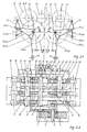
- Fig. 2.1.
- Prinzipdarstellung des Vierpunktantriebes mit zwölf Antriebsgliedern und verstellbarer Zwischenrast
- Fig. 2.2.
- Draufsicht nach Fig. 2.1.
- Fig. 3.1.
- Prinzipdarstellung des achtgliedrigen Räderkoppelgetriebes mit verstellbarer Zwischenrast
- Fig. 3.2.
- Draufsicht nach Fig. 3.1.
- Fig. 4.1.
- Prinzipdarstellung des Zweipunkt- und Mehrpunktantriebes mit zwölf Antriebsgliedern mit verstellbarer Zwischenrast mittels Schieberad
- Fig. 4.2.
- Draufsicht nach Fig. 4.1.
- Fig. 5.
- Ablaufkurve des Stößels mit der Darstellung des veränderlichen Weg-Zeitverhaltens vom Stößel für eine Rast- bzw. Ziehphase
Die zentrale Antriebswelle 1, vom sogenannten Primärantrieb kommend trägt einerseits das fest
- Fig. 1.1.
- Schematic diagram of the two-point and multi-point drive with twelve drive elements and adjustable intermediate stop
- Fig. 1.2.
- Top view according to Fig. 1.1.
- Fig. 2.1.
- Schematic diagram of the four-point drive with twelve drive links and adjustable intermediate catch
- Fig. 2.2.
- Top view according to Fig. 2.1.
- Fig. 3.1.
- Schematic diagram of the eight-link geared transmission with adjustable intermediate stop
- Fig. 3.2.
- Top view according to Fig. 3.1.
- Fig. 4.1.
- Schematic representation of the two-point and multi-point drive with twelve drive elements with adjustable intermediate stop by means of a sliding wheel
- Fig. 4.2.
- Top view according to Fig. 4.1.
- Fig. 5.
- Ram curve of the ram with the representation of the variable path-time behavior of the ram for a rest or pull phase
The central drive shaft 1, coming from the so-called primary drive, carries on the one hand the firmly attached
Das Rad 2 treibt das auf der Vorgelegewelle 9 angeordnete Vorgelegerad 5 an. Gleichfalls treibt das Rad 3 bei in Eingriff befindlicher Kupplung 4 das auf der zentralen Zwischenradwelle 7 fest angeordnete Zwischenrad 6 an, welches seinerseits das auf der Vorgelegewelle 13 angeordnete Vorgelegerad 8 antreibt. Das Vorgelegerad 5 treibt über das starr mit ihm verbundene Ritzel 10 die Exzenterräder 11 und 12, welche ihrerseits die Exzenter 24a bzw. 24b tragen, wobei die Räder 11 und 12 miteinander im Eingriff stehen.
Vorgelegerad 8 treibt über das starr mit ihm verbundene Ritzel 14 die Exzenterräder 15 und 16 an, welche miteinander im Eingriff stehen und die die Exzenter 17a bzw. 17b tragen.
In der weiteren Beschreibung wird nur der Getriebezug eines Druckpunktes beschrieben, wobei die Bezugszeichen mit einem a ergänzt sind. Damit soll dokumentiert werden, daß der gleiche Getriebezug nochmals spiegelbildlich für den zweiten Druckpunkt vorhanden ist.
Der Exzenter 17a ist über die Koppel 18a mit dem äußeren Hebelarm der Hebelwelle 19a verbunden. Der innere Hebelarm der Hebelwelle 19a ist über eine Koppel 20a an den in einem festen Drehpunkt gelagerten Winkelhebel 21a angelenkt. Der zweite Anlenkpunkt des Winkelhebels 21a ist über eine Koppel 22a mit der Schwinge 23a verbunden, wobei von den beiden anderen Anlenkpunkten einer mit dem Exzenter 24a und der andere über das Pleuel 25a mit dem Stößel 26 verbunden ist.
Auf der Zwischenradwelle 7 ist hinter dem Zwischenrad 6 der Schleichgang 27 angeordnet, der mittels der formschlüssigen Kupplung 28 zuschaltbar ist. Die Getriebeglieder Exzenter 24, Schwinge 23, Pleuel 25 und der Stößel 26 stellen die Antriebskette für die Arbeitsbewegung dar. Die Getriebeglieder Exzenter 17, Koppel 18, Hebelwelle 19, Koppel 20, Winkelhebel 21 und Koppel 22 bilden die Arbeitskette der Schnellaufbewegung.The
In the further description, only the gear train of a pressure point is described, the reference symbols being supplemented with an a. This is to document that the same gear train is again mirrored for the second pressure point.
The eccentric 17a is connected via the
On the
Die Verstellung der Exzenter 24a und 24b gegenüber den Exzentern 17a und 17b zur Erzielung veränderter Bewegungsfunktionen der Zwischenrast erfolgt dadurch, daß die formschlüssige Kupplung außer Eingriff gebracht wird. Gleichzeitig wird der auf Zwischenradwelle frei drehend angeordnete Schleichgangantrieb 27 über die Kupplung 28 formschlüssig mit der Zwischenradwelle 7 verbunden. Nunmehr ist es möglich, Rad 3 gegenüber Rad 2 auf der Antriebswelle 1 zu verdrehen. Nach Wiedereinrücken der Kupplung 4 ist der Gelenkantrieb wieder arbeitsfähig und das stoßfreie Aufsetzen des Stößels auf die durch das Kissen gehaltenen Werkzeugteile, beispielsweise Blechhalterrahmen, für den jeweiligen Werkzeugsatz entsprechend der Ablaufkurve nach Fig. 5 gewährleistet. In der Fig. 5 sind die Weg-Zeit-Verläufe der Stößelbewegung für die zwei Einstellungen der Exzenterräder zueinander dargestellt.
Bei dem Vierpunktantrieb nach Fig. 2.2. trägt die Antriebswelle 6 einerseits das Vorgelegerad 5, das mit dem auf der Kupplungswelle 3 angeordneten Vorgelegerad 4 in Eingriff steht.
Auf der Kupplungswelle 3 ist noch die Kupplung und Bremse 2 sowie das Schwungrad 1 angeordnet. Andererseits ist auf der Antriebswelle 6 das Rad 7 fest angeordnet. Dieses steht mit dem auf der Vorgelegewelle 13 angeordneten Vorgelegerad 10 in Wirkverbindung. Weiterhin sind auf der Vorgelegewelle 13 noch die Ritzel 14 und 15 angeordnet, die die Exzenterräder 16 und 18 antreiben, wobei diese wiederum auf die Exzenterräder 17 und 19 wirken.
Auf der äußeren Fortsetzung der Antriebswelle 6 sind lose das Rad 8 und die mit dem Rad 8 verbundene Kupplung 9 angeordnet. Das Rad 8 steht über das Zwischenrad 11, das mit dem Schleichgang 42 und der zugehörigen Formschlußkupplung 43 verbunden ist, mit dem auf der Vorgelegewelle 20 angeordneten Vorgelegerad 12 in Wirkverbindung. Diese Vorgelegewelle 20 besitzt das Ritzel 21, welches das Exzenterrad 22 und das mit diesem in Eingriff stehende Exzenterrad 23 auftreibt.The adjustment of the
In the four-point drive according to Fig. 2.2. the
The clutch and
The
Der Exzenter 24 des Exzenterrades 23 ist über die Koppeln 26 mit den äußeren Hebelarmen der Hebelwelle 28 verbunden. Analog dazu ist der Exzenter 25 des Exzenterrades 22 über die Koppeln 27 mit den äußeren Hebelarmen der Hebelwelle 29 verbunden. Der restliche Getriebeaufbau entspricht identisch den im ersten Beispiel beschriebenen. Dabei sind die Bezugszeichen mit a und b ergänzt, um die jeweils dahinter liegenden Antriebselemente entsprechend dem Vierpunktantrieb zu verdeutlichen. So sind zwischen den inneren Anlenkpunkten der Hebelwellen 28, 29, den Exzentern 38a, b und 39a, b und dem Stößel 44 die Koppeln 30, 31 die Winkelhebel 32, 33, die Koppeln 34, 35, die Schwingen 36, 37 und die Pleuel 40, 41 angeordnet.
Die Verstellung der Exzenter 24, 25 gegenüber den Exzentern 38, 39 zur Erzielung veränderter Bewegungsfunktionen der Zwischenrast erfolgt auch analog dem ersten Beispiel, so daß hier auf eine wiederholende Beschreibung verzichtet wird.The eccentric 24 of the
The adjustment of the
Der Antrieb mittels eines Räderkoppelgetriebes, wie in den Figuren 3.1. und 3.2. gezeigt, erfolgt über die zentrale Antriebswelle 1, auf der einerseits fest das Rad 2 und andererseits lose das Rad 3 angeordnet ist. Das Rad 3 ist mit der formschlüssigen Kupplung 4 versehen. Gleichzeitig treibt es direkt das auf der Vorgelegewelle 18 sitzende Vorgelegerad 14 und über das fest auf der zentralen Zwischenradwelle 16 angeordnete Zwischenrad 15 das auf der Vorgelegewelle 22 sitzende Vorgelegerad 17 an. Analog ist das Rad 2 direkt mit dem auf der Vorgelegewelle 8 sitzenden Vorgelegerad 5 und über das lose auf der Zwischenradwelle 16 angeordnete Zwischenrad 6 mit dem auf der Vorgelegewelle 11 sitzenden Vorgelegerad 7 verbunden. Außerhalb des Getriebes ist auf der Zwischenradwelle 16 der Schleichgangantrieb 35 mit der Formschlußkupplung 34 angeordnet.The drive by means of a wheel coupling gear, as in FIGS. 3.1. and 3.2. shown, takes place via the central drive shaft 1, on the one hand the
Zur Bewegungsbeeinflussung ist das Ritzel 19 der Vorgelegewelle 18 über das Zwischenrad 20 mit dem Exzenterrad 21 wirkverbunden. Außerdem steht das Ritzel 23 über Zwischenrad 24 und Ritzel 25 mit dem Exzenterrad 26 in Eingriff. Für die Bewegungsübertragung ist das Ritzel 9 der Vorgelegewelle 8 mit dem Exzenterrad 10 und das Ritzel 12 der Vorgelegewelle 11 mit dem Exzenterrad 13 verbunden. Weiterhin ist spiegelbildlich an den Exzenterrädern 10 und 13 jeweils ein Exzenter 27a bzw. 27b angeordnet, der über die Schwinge 28a, 28b, den Dreifach-Gelenkpunkt 31a, 31b und das Pleuel 32a, 32b mit dem Stößel 33 verbunden ist. Der Dreifach-Gelenkpunkt 31a, 31b steht über die Koppel 30a, 30b mit dem Exzenter 29a, 29b der Exzenterräder 21, 26 gleichfalls in Wirkverbindung.
Die am Stöße31 33 gelenkig gelagerten Pleuel 32 werden von den Koppelgliedern 28 und 30 angetrieben. Die Exzenterräder 10, 13 mit den Exzentern 27a, 27b und die Exzenterräder 21, 26 mit den Exzentern 29 sind in der gewählten gegenläufigen Anordnung für die beabsichtigte Zwischenrast-Bewegung besonders gut geeignet. Aber auch der Lauf mit gleichen Drehrichtungen, wie er unter Wegfall der betreffenden Zwischenräder erreichbar ist, bringt brauchbare Ergebnisse.To influence movement, the
The connecting rods 32 articulated on the joints 31 33 are driven by the
Vom Antrieb her gesehen treibt die Welle 1 mittels Rad 2 über Vorgelegerad 5, Zwiwschenrad 6 und Vorgelegerad 7 die Ritzel 9 und 12, die diagonal gegenüberliegenden Exzenterräder 10 und 13, auf dem Exzentern 27a, 27b die Schwingen 28 angeordnet sind, an.
Gleichzeitig treibt die Antriebswelle 1 über Formschlußkupplung 4 und Rad 3, Vorgelegerad 14, Zwischenrad 15, Vorgelegerad 17, die Ritzel 19, 23 und die Zwischenräder 20, 24 und Ritzel 25 die Exzenterräder 21, 26, auf deren Exzentern 29a, 29b die Koppeln 30 angeordnet sind, an.Seen from the drive, the shaft 1 drives the
At the same time, the drive shaft 1 drives the
Die Schwingen 28a, 28b und Koppeln 30a, 30b treffen in den Dreifachgelenkpunkten 31a, 31b zusammen und treiben die Pleuel 32a, 32b und damit den Stößel 33 a.
Die durch den gesamten Komplex der Antriebe geführte zentrale Antriebswelle 1 sichert damit den Gleichlauf aller Exzenterräder 10, 13 des Komplexes. Die Zwischenradwelle 16, die ebenfalls durch den gesamten Komplex geführt ist, sichert den Gleichlauf aller Exzenterräder 21, 26 des Komplexes. Nach der jeweiligen Einstellung über die Formschlußkupplung 4 sind die Winkelstellungen der Wellen 1 und 16 zueinander festgelegt. Der Schleichgangantrieb 34 mit Formschlußkupplung 35 dient sowohl zur Zustellung von Zwischenradwelle 16 gegenüber Antriebswelle 1, die von der zentralen Bremse den Gesamtantrieben gehalten wird als auch zur Schleichgangbewegung des gesamten Pressenantriebes.
Bei der vierten Ausführungsform ist auf der zentralen Antriebswelle 1 das Rad 2 fest und das Rad 3 lose angeordnet. In Wirkverbindung dazu ist die pfeilverzahnte Schiebewelle 4 angeordnet. Das Rad 2 steht mit dem auf der Vorgelegewelle 9 angeordneten Vorgelegerad 5 in Wirkverbindung, wobei weiterhin das Ritzel 10 der Vorgelegewelle 9 die Exzenterräder 11 und 12 antreibt. Andererseits steht das Rad 3 über das auf der zentralen Zwischenradwelle 7 angeordnete Zwischenrad 6 mit dem auf der Vorgelegewelle 13 sitzenden Vorgelegerad 8 in Wirkverbindung. Dabei treibt das Ritzel 14 der Vorgelegewelle 13 die Exzenterräder 15 und 16 an. Die Exzenterräder 11, 12 tragen die Exzenter 24a bzw. 24b und die Exzenterräder 15, 16 sind mit den Exzentern 17a bzw. 17b versehen. Analog zu den ersten beiden Ausführungsformen sind hier spiegelbildlich die gleichen Antriebelemente vorhanden.The
The central drive shaft 1 guided through the entire complex of drives thus ensures that all
In the fourth embodiment, the
In der weiteren Bezeichnung wird zur Vereinfachung auch wieder auf die Bezeichnung a und b bei den Bezugszeichen verzichtet. So ist der Exzenter 17 über die Koppel 18 mit den äußeren Anlenkpunkt der Hebelwelle 19 verbunden. Der andere Anlenkpunkt ist über die Koppel 20 mit dem Winkelhebel 21 verbunden, wobei der letztere über die Koppel 22 an die Schwinge 23 angelenkt ist. Diese Schwinge 23 ist mit ihren anderen beiden Anlenkpunkten zum einen an den Exzenter 24 und zum anderen über das Pleuel 25 an den Stößel 26 angelenkt. An einem Ende der Schiebewelle 4 ist das Axiallager 27 angeordnet, das wiederum über Stellspindeln 28a, 28b und Antriebsrädern 29 mit dem Stellmotor 30 verbunden ist.
Die Verstellung der Exzenter 17 gegenüber den Exzentern 24 erfolgt durch Verschieben der Schiebewelle 4 in Längsrichtung. Dadurch kommt es zur Verschiebung des Rades 3 zum Rad 2. Diese Bewegung überträgt sich über die Getriebeglieder auf die Exzenter 17 und 24. Somit wird der im ersten Beispiel näher beschriebene Effekt zur Erzielung der Erfindungsaufgabe erreicht.
Zum Rahmen der Erfindung gehört auch, daß zwar die Lösung im zweiten Ausführungsbeispiel für eine Einzelmaschine als Kissenziehpresse dargestellt ist, aber auch als ein Antriebsmodul eines Tranferpressenkomplexes angesehen werden kann. Dabei erfolgt die Kopplung derartiger Komplexe über Gelenkwellen mit einem zentralen Antriebskomplex.
Die Lösung nach dem vierten Ausführungsbeispiel kann natürlich auch in einen Vierpunktantrieb übertragen werden. Das dritte Ausführungsbeispiel ist als Zweipunktantrieb mit durchgehenden Wellen für Großraumtransferpressen. Eine Ausführung als Vierpunktantriebsmodul ist durch symmetrische Ergänzung des Räder-Koppelgetriebes möglich.In the rest of the designation, the designations a and b are again omitted from the reference symbols for simplification. The eccentric 17 is connected via the
The eccentric 17 is adjusted relative to the eccentric 24 by moving the sliding
The scope of the invention also includes that although the solution in the second exemplary embodiment for a single machine is shown as a pillow press, it can also be regarded as a drive module of a transfer press complex. Such complexes are coupled via cardan shafts to a central drive complex.
The solution according to the fourth embodiment can of course also be transferred to a four-point drive. The third embodiment is a two-point drive with through shafts for large-capacity transfer presses. A version as a four-point drive module is possible through the symmetrical addition of the wheel coupling gear.
Claims (9)
dadurch gekennzeichnet,
daß die Antriebsglieder für die Stößelschnellaufbewegung und die Arbeitsbewegung des Stößels durch jeweils separate Exzenter- oder Kurbelräder antreibbar sind.Drive for the plunger of mechanical presses, which is designed as a multi-link articulated drive, the drive of the plunger for its working movement being carried out by a drive eccentric wheel which is connected to the pressure point of the plunger by a rocker arm and a connecting rod, which together form a pair of buckling points which are additionally operatively connected to the levers for influencing the ram high-speed movement,
characterized,
that the drive members for the plunger high-speed movement and the working movement of the plunger can be driven by separate eccentric or crank wheels.
dadurch gekennzeichnet,
daß die separaten Exzenter- oder Kurbelräder zueinander verstellbar sind, derart, daß auf einer Antriebswelle ein festes Rad und ein loses über Einrichtungen verstellbares Rad angeordnet sind, von denen das feste direkt in eines der Exzenterantriebsräder eingreift und das verstellbare über ein auf einer Zwischenradwelle sitzende Zwischenrad das andere Exzenterantriebsrad antreibt.Drive for the ram of mechanical presses according to claim 1,
characterized,
that the separate eccentric or crank wheels are mutually adjustable, such that a fixed wheel and a loose wheel which can be adjusted via devices are arranged on a drive shaft, of which the fixed engages directly in one of the eccentric drive wheels and the adjustable wheel via an intermediate wheel seated on an intermediate wheel shaft drives the other eccentric drive gear.
dadurch gekennzeichnet,
daß anstelle jeweils eines Exzenterantriebsradpaares auch zwei hintereinander in Wirkverbindung stehende Exzenterantriebsräderpaare angeordnet sind.Drive for the ram of mechanical presses according to claims 1 and 2,
characterized,
that instead of one pair of eccentric drive wheels, there are also two pairs of eccentric drive wheels that are operatively connected one behind the other.
dadurch gekennzeichnet,
daß die Verbindung des verdrehbaren Exzenter- oder Kurbelrades, mit der Antriebswelle über das lose Rad und eine schaltbare Formschlußkupplung herstellbar ist.Drive for the ram of mechanical presses according to claims 1 to 3,
characterized,
that the connection of the rotatable eccentric or crank wheel with the drive shaft via the loose wheel and a switchable positive coupling can be produced.
dadurch gekennzeichnet,
daß die Verbindung des verdrehbaren Exzenter- oder Kurbelrades 3 mit dem fest auf der Antriebswelle (1) sitzendem Rad (2) über eine gegenläufige schrägverzahnte Schiebewelle (4), die axial verschiebbar ist, herstellbar ist.Drive for the ram of mechanical presses according to claims 1 to 3,
characterized,
that the connection of the rotatable eccentric or crank wheel 3 with the wheel (2) seated firmly on the drive shaft (1) can be produced via an opposing helical sliding shaft (4) which is axially displaceable.
dadurch gekennzeichnet,
daß die Zwischenradwelle die weiteren Getriebe gleicher Art einer Maschine untereinander synchronisiert.Drive for the ram of mechanical presses according to claims 1 to 3,
characterized,
that the idler gear shaft synchronizes the other gears of the same type with each other.
wobei der Antrieb des Stößels für dessen Arbeitsbewegung von einem Antriebsexzenterrad erfolgt, der durch eine Schwinge und ein Pleuel mit dem Druckpunkt des Stößels verbunden ist, die zusammen ein Knickstelzenpaar bilden, mit dem zusätzlich die Hebel zur Beeinflussung der Stößelschnellaufbewegung in Wirkverbindung stehen,
dadurch geknnzeichnet,
daß die Antriebsglieder für die Stößelschnellaufbewegung und die Arbeitsbewegung des Stößels durch jeweils separate Exzenter- oder Kurbelräder antreibbar sind,
derart,daß zur Beeinflussung für die Stößelschnellaufbewegung die Exzenter- oder Kurbelräder (21, 26) auf einer gesonderten Welle angeordnet sind.Drive for the ram of mechanical presses, which is designed as a multi-link articulated drive,
wherein the plunger is driven for its working movement by a drive eccentric wheel which is connected to the pressure point of the plunger by a rocker arm and a connecting rod, which together form a pair of buckles with which the levers for influencing the plunger rapid movement are also operatively connected,
marked by
that the drive elements for the tappet high-speed movement and the working movement of the tappet can be driven by separate eccentric or crank wheels,
in such a way that the eccentric or crank wheels (21, 26) are arranged on a separate shaft for influencing the tappet high-speed movement.
dadurch gekennzeichnet,
daß die Verbindung des verdrehbaren Exzenter- oder Kurbelrades mit der Antriebswelle (1) über das lose Rad (3) und eine schaltbare Formabschlußkupplung (4) verstellbar ist.Drive for the ram of mechanical presses according to claim 8,
characterized,
that the connection of the rotatable eccentric or crank wheel with the drive shaft (1) via the loose wheel (3) and a switchable form-locking coupling (4) is adjustable.
dadurch gekennzeichnet,
daß der normalerweise vorhandene Schleichgangantrieb zusätzlich die Verstellbewegung der Exzenter zueinander ausführt.Drive for the ram of mechanical presses according to claims 1 to 8,
characterized,
that the crawl speed drive normally present also carries out the adjusting movement of the eccentrics to one another.
Applications Claiming Priority (2)
| Application Number | Priority Date | Filing Date | Title |
|---|---|---|---|
| DE4130004A DE4130004A1 (en) | 1991-09-10 | 1991-09-10 | DRIVE FOR THE PUSHER OF MECHANICAL PRESSES |
| DE4130004 | 1991-09-10 |
Publications (3)
| Publication Number | Publication Date |
|---|---|
| EP0531804A2 true EP0531804A2 (en) | 1993-03-17 |
| EP0531804A3 EP0531804A3 (en) | 1993-05-26 |
| EP0531804B1 EP0531804B1 (en) | 1996-05-29 |
Family
ID=6440242
Family Applications (1)
| Application Number | Title | Priority Date | Filing Date |
|---|---|---|---|
| EP92114577A Expired - Lifetime EP0531804B1 (en) | 1991-09-10 | 1992-08-27 | Drive for the ram of a mechanical press |
Country Status (4)
| Country | Link |
|---|---|
| EP (1) | EP0531804B1 (en) |
| JP (1) | JPH05269597A (en) |
| DE (2) | DE4130004A1 (en) |
| ES (1) | ES2087373T3 (en) |
Families Citing this family (2)
| Publication number | Priority date | Publication date | Assignee | Title |
|---|---|---|---|---|
| DE4308475A1 (en) * | 1993-03-17 | 1994-09-22 | Pressen Engineering Essen Gmbh | Drive for the plunger of a cutting press or metal-forming machine tool |
| DE4441569A1 (en) | 1994-11-23 | 1996-05-30 | Erfurt Umformtechnik Gmbh | Process for low-noise and shock-free alignment of the upper and lower tools of mechanical presses and ram drives with a device for carrying out the process |
Citations (7)
| Publication number | Priority date | Publication date | Assignee | Title |
|---|---|---|---|---|
| GB424315A (en) * | 1933-05-13 | 1935-02-19 | Alexandre Felicien Hubert | Arrangement of connecting rods for eccentric presses particularly adapted for drawing and stamping |
| US2112011A (en) * | 1931-04-18 | 1938-03-22 | Gen Machinery Corp | Press |
| FR953349A (en) * | 1947-09-04 | 1949-12-05 | A Hubert M Juy Ets | Linkage for compressing machines and other similar long stroke machines |
| US2857768A (en) * | 1954-04-30 | 1958-10-28 | Giesserei & Maschinenfabrik Os | Driving and control device |
| FR2097838A5 (en) * | 1970-06-10 | 1972-03-03 | Zdarske Strojirny A Slevarny | |
| GB1433112A (en) * | 1974-06-10 | 1976-04-22 | Us Industries Inc | Driving linkages for reciprocating the slides of mechanical presses |
| US4138904A (en) * | 1977-07-20 | 1979-02-13 | Verson Allsteel Press Company | Link drive mechanism for mechanical presses |
Family Cites Families (6)
| Publication number | Priority date | Publication date | Assignee | Title |
|---|---|---|---|---|
| US2688296A (en) * | 1950-07-22 | 1954-09-07 | Danly Mach Specialties Inc | Triple action reciprocating crown press |
| DE2306171A1 (en) * | 1973-02-08 | 1974-08-22 | Schuler Gmbh L | PRESS, IN PARTICULAR CUTTING PRESS |
| US4107973A (en) * | 1977-08-04 | 1978-08-22 | Gulf & Western Manufacturing Company | Press drive mechanism |
| DE3142679C2 (en) * | 1981-10-28 | 1984-05-10 | Maschinenfabrik Müller-Weingarten AG, 7987 Weingarten | Crank-operated lever and joint drive for press rams |
| DE3712497A1 (en) * | 1987-04-13 | 1988-10-27 | Rudolf Klaschka | Eccentric press |
| DE3736353A1 (en) * | 1987-10-27 | 1989-05-11 | Rudolf Klaschka | Long-stroke eccentric press |
-
1991
- 1991-09-10 DE DE4130004A patent/DE4130004A1/en not_active Withdrawn
-
1992
- 1992-08-27 EP EP92114577A patent/EP0531804B1/en not_active Expired - Lifetime
- 1992-08-27 DE DE59206405T patent/DE59206405D1/en not_active Expired - Fee Related
- 1992-08-27 ES ES92114577T patent/ES2087373T3/en not_active Expired - Lifetime
- 1992-09-09 JP JP4240268A patent/JPH05269597A/en active Pending
Patent Citations (7)
| Publication number | Priority date | Publication date | Assignee | Title |
|---|---|---|---|---|
| US2112011A (en) * | 1931-04-18 | 1938-03-22 | Gen Machinery Corp | Press |
| GB424315A (en) * | 1933-05-13 | 1935-02-19 | Alexandre Felicien Hubert | Arrangement of connecting rods for eccentric presses particularly adapted for drawing and stamping |
| FR953349A (en) * | 1947-09-04 | 1949-12-05 | A Hubert M Juy Ets | Linkage for compressing machines and other similar long stroke machines |
| US2857768A (en) * | 1954-04-30 | 1958-10-28 | Giesserei & Maschinenfabrik Os | Driving and control device |
| FR2097838A5 (en) * | 1970-06-10 | 1972-03-03 | Zdarske Strojirny A Slevarny | |
| GB1433112A (en) * | 1974-06-10 | 1976-04-22 | Us Industries Inc | Driving linkages for reciprocating the slides of mechanical presses |
| US4138904A (en) * | 1977-07-20 | 1979-02-13 | Verson Allsteel Press Company | Link drive mechanism for mechanical presses |
Also Published As
| Publication number | Publication date |
|---|---|
| EP0531804B1 (en) | 1996-05-29 |
| DE4130004A1 (en) | 1993-03-11 |
| JPH05269597A (en) | 1993-10-19 |
| EP0531804A3 (en) | 1993-05-26 |
| DE59206405D1 (en) | 1996-07-04 |
| ES2087373T3 (en) | 1996-07-16 |
Similar Documents
| Publication | Publication Date | Title |
|---|---|---|
| EP0786297A1 (en) | Drive for a forming machine | |
| DE19622405C2 (en) | Mechanical press | |
| DE803142C (en) | Crank gear | |
| DE3134096C2 (en) | Walking beam conveyor | |
| EP0395964A1 (en) | Apparatus for balancing inerta forces in a crank operated machine, in particular a punching machine | |
| EP0927630A1 (en) | Press, in particular punch press | |
| EP0724953B1 (en) | Punch press with extended space for mounting dies | |
| DE102007015467B4 (en) | Cam mechanism with two take-off rollers, method for producing such a cam gear, program for performing the steps of the method, and punch-bending machine with such a cam mechanism | |
| EP0531804B1 (en) | Drive for the ram of a mechanical press | |
| DE3141650C2 (en) | Forging machine | |
| DE3201836A1 (en) | "THREE-KNIFE CUTTER" | |
| EP1429876B1 (en) | Drive system for a rolling mill | |
| DE102015117200B4 (en) | Embossing press and method for its operation | |
| DE2156660A1 (en) | Device and method for rolling gears | |
| DE3601809C1 (en) | Forming machine with ejector on the ram side | |
| DE746719C (en) | Crank assembly | |
| DE69826958T2 (en) | slab sizing | |
| DE3311520C2 (en) | Ballast gearbox for generating a periodically swelling rotary movement of the drive shaft of a transfer device in a press | |
| CH666328A5 (en) | HYDRAULIC TELEMOTOR REVERSING DRIVE. | |
| DE1939888A1 (en) | Forging press | |
| DE954685C (en) | Drawing press | |
| EP2490886A2 (en) | Working method and assembly for operating presses | |
| DE1230652B (en) | Horizontal forging and upsetting machine | |
| DE2545386A1 (en) | Driving device for vibrating moulds - which automatically adjusts the vibration width | |
| DE10241106A1 (en) | Press has secondary movement converter arranged at frame to reciprocatingly move balanced weight contrary to slide |
Legal Events
| Date | Code | Title | Description |
|---|---|---|---|
| PUAI | Public reference made under article 153(3) epc to a published international application that has entered the european phase |
Free format text: ORIGINAL CODE: 0009012 |
|
| AK | Designated contracting states |
Kind code of ref document: A2 Designated state(s): DE ES FR GB IT SE |
|
| PUAL | Search report despatched |
Free format text: ORIGINAL CODE: 0009013 |
|
| AK | Designated contracting states |
Kind code of ref document: A3 Designated state(s): DE ES FR GB IT SE |
|
| 17P | Request for examination filed |
Effective date: 19931118 |
|
| 17Q | First examination report despatched |
Effective date: 19950105 |
|
| GRAH | Despatch of communication of intention to grant a patent |
Free format text: ORIGINAL CODE: EPIDOS IGRA |
|
| GRAA | (expected) grant |
Free format text: ORIGINAL CODE: 0009210 |
|
| AK | Designated contracting states |
Kind code of ref document: B1 Designated state(s): DE ES FR GB IT SE |
|
| REG | Reference to a national code |
Ref country code: ES Ref legal event code: BA2A Ref document number: 2087373 Country of ref document: ES Kind code of ref document: T3 |
|
| REF | Corresponds to: |
Ref document number: 59206405 Country of ref document: DE Date of ref document: 19960704 |
|
| REG | Reference to a national code |
Ref country code: ES Ref legal event code: FG2A Ref document number: 2087373 Country of ref document: ES Kind code of ref document: T3 |
|
| ITF | It: translation for a ep patent filed |
Owner name: SOCIETA' ITALIANA BREVETTI S.P.A. |
|
| GBT | Gb: translation of ep patent filed (gb section 77(6)(a)/1977) |
Effective date: 19960705 |
|
| ET | Fr: translation filed | ||
| PLBE | No opposition filed within time limit |
Free format text: ORIGINAL CODE: 0009261 |
|
| STAA | Information on the status of an ep patent application or granted ep patent |
Free format text: STATUS: NO OPPOSITION FILED WITHIN TIME LIMIT |
|
| 26N | No opposition filed | ||
| PGFP | Annual fee paid to national office [announced via postgrant information from national office to epo] |
Ref country code: SE Payment date: 19990616 Year of fee payment: 8 |
|
| PGFP | Annual fee paid to national office [announced via postgrant information from national office to epo] |
Ref country code: FR Payment date: 19990728 Year of fee payment: 8 |
|
| PGFP | Annual fee paid to national office [announced via postgrant information from national office to epo] |
Ref country code: DE Payment date: 19990925 Year of fee payment: 8 |
|
| PGFP | Annual fee paid to national office [announced via postgrant information from national office to epo] |
Ref country code: ES Payment date: 20000718 Year of fee payment: 9 |
|
| PGFP | Annual fee paid to national office [announced via postgrant information from national office to epo] |
Ref country code: GB Payment date: 20000815 Year of fee payment: 9 |
|
| PG25 | Lapsed in a contracting state [announced via postgrant information from national office to epo] |
Ref country code: SE Free format text: LAPSE BECAUSE OF NON-PAYMENT OF DUE FEES Effective date: 20000828 |
|
| EUG | Se: european patent has lapsed |
Ref document number: 92114577.7 |
|
| PG25 | Lapsed in a contracting state [announced via postgrant information from national office to epo] |
Ref country code: FR Free format text: LAPSE BECAUSE OF NON-PAYMENT OF DUE FEES Effective date: 20010430 |
|
| PG25 | Lapsed in a contracting state [announced via postgrant information from national office to epo] |
Ref country code: DE Free format text: LAPSE BECAUSE OF NON-PAYMENT OF DUE FEES Effective date: 20010501 |
|
| REG | Reference to a national code |
Ref country code: FR Ref legal event code: ST |
|
| PG25 | Lapsed in a contracting state [announced via postgrant information from national office to epo] |
Ref country code: GB Free format text: LAPSE BECAUSE OF NON-PAYMENT OF DUE FEES Effective date: 20010827 |
|
| PG25 | Lapsed in a contracting state [announced via postgrant information from national office to epo] |
Ref country code: ES Free format text: LAPSE BECAUSE OF NON-PAYMENT OF DUE FEES Effective date: 20010828 |
|
| GBPC | Gb: european patent ceased through non-payment of renewal fee |
Effective date: 20010827 |
|
| REG | Reference to a national code |
Ref country code: ES Ref legal event code: FD2A Effective date: 20020911 |
|
| PG25 | Lapsed in a contracting state [announced via postgrant information from national office to epo] |
Ref country code: IT Free format text: LAPSE BECAUSE OF NON-PAYMENT OF DUE FEES;WARNING: LAPSES OF ITALIAN PATENTS WITH EFFECTIVE DATE BEFORE 2007 MAY HAVE OCCURRED AT ANY TIME BEFORE 2007. THE CORRECT EFFECTIVE DATE MAY BE DIFFERENT FROM THE ONE RECORDED. Effective date: 20050827 |