EP0531608A2 - Self-contained change speed apparatus for a bicycle - Google Patents
Self-contained change speed apparatus for a bicycle Download PDFInfo
- Publication number
- EP0531608A2 EP0531608A2 EP92104800A EP92104800A EP0531608A2 EP 0531608 A2 EP0531608 A2 EP 0531608A2 EP 92104800 A EP92104800 A EP 92104800A EP 92104800 A EP92104800 A EP 92104800A EP 0531608 A2 EP0531608 A2 EP 0531608A2
- Authority
- EP
- European Patent Office
- Prior art keywords
- transmission
- clutches
- pawls
- clutch
- change speed
- Prior art date
- Legal status (The legal status is an assumption and is not a legal conclusion. Google has not performed a legal analysis and makes no representation as to the accuracy of the status listed.)
- Granted
Links
Images


Classifications
-
- B—PERFORMING OPERATIONS; TRANSPORTING
- B62—LAND VEHICLES FOR TRAVELLING OTHERWISE THAN ON RAILS
- B62M—RIDER PROPULSION OF WHEELED VEHICLES OR SLEDGES; POWERED PROPULSION OF SLEDGES OR SINGLE-TRACK CYCLES; TRANSMISSIONS SPECIALLY ADAPTED FOR SUCH VEHICLES
- B62M11/00—Transmissions characterised by the use of interengaging toothed wheels or frictionally-engaging wheels
- B62M11/04—Transmissions characterised by the use of interengaging toothed wheels or frictionally-engaging wheels of changeable ratio
- B62M11/14—Transmissions characterised by the use of interengaging toothed wheels or frictionally-engaging wheels of changeable ratio with planetary gears
- B62M11/16—Transmissions characterised by the use of interengaging toothed wheels or frictionally-engaging wheels of changeable ratio with planetary gears built in, or adjacent to, the ground-wheel hub
-
- B—PERFORMING OPERATIONS; TRANSPORTING
- B62—LAND VEHICLES FOR TRAVELLING OTHERWISE THAN ON RAILS
- B62M—RIDER PROPULSION OF WHEELED VEHICLES OR SLEDGES; POWERED PROPULSION OF SLEDGES OR SINGLE-TRACK CYCLES; TRANSMISSIONS SPECIALLY ADAPTED FOR SUCH VEHICLES
- B62M11/00—Transmissions characterised by the use of interengaging toothed wheels or frictionally-engaging wheels
- B62M11/04—Transmissions characterised by the use of interengaging toothed wheels or frictionally-engaging wheels of changeable ratio
- B62M11/14—Transmissions characterised by the use of interengaging toothed wheels or frictionally-engaging wheels of changeable ratio with planetary gears
- B62M11/18—Transmissions characterised by the use of interengaging toothed wheels or frictionally-engaging wheels of changeable ratio with planetary gears with a plurality of planetary gear units
Landscapes
- Engineering & Computer Science (AREA)
- Chemical & Material Sciences (AREA)
- Combustion & Propulsion (AREA)
- Transportation (AREA)
- Mechanical Engineering (AREA)
- Structure Of Transmissions (AREA)
Abstract
Description
- The present invention relates to an improvement in a clutch mechanism mounted in a self-contained change speed apparatus for use on a bicycle.
- Conventional self-contained change speed apparatus, as disclosed in U.S. Patent No. 5.078,664 and U.K. Patent application GB2166503A, employ a plurality of clutches in the form of pawl clutches and claw clutches and a clutch controller for providing multistage speeds. In these examples, operation of a shift lever is transmitted directly to the clutch controller. Consequently, a shift of the shift lever simultaneously results in a shift of the clutch controller with no substantial "lag" therebetween.
- On the other hand, a drive torque is applied to engaging regions of a claw clutch, which acts as a resistance to disengagement of the claw clutch to impede smooth operation of the clutch controller. In the case of a bicycle, drive is variable with pedal positions, that is drive is weaker in upper and lower dead point regions for reasons of human engineering, with the result that diminished torque acts on the clutches. Consequently, only a minimum operating force is required for a smooth change speed operation if the clutches are operated when the pedals are in the upper and lower dead point regions. However, it is extremely difficult to operate the shift lever with such timing. Normally, therefore, a change speed operation is carried out with a great operating force overcoming a considerable resistance to disengagement. This involves an unsmooth clutch operation and shocks of shifting.
- In the art of claw clutches, a spring or the like is sometimes incorporated into an individual clutch mechanism in order to avoid an overload. This results in a "lag" of the clutch controller, whereby the clutch is operated in a low disengagement resistance condition. However, the individual clutch mechanisms are not designed to cooperate with one another, nor are the clutches and springs. Thus, the addition of such springs makes little contribution to smooth operation of the change speed apparatus.
- An object of the present invention is to provide a self-contained change speed apparatus for automatically effecting change speed in upper and lower dead point regions of the pedals where transmitted torque becomes weak.
- The above object is fulfilled, according to the present invention, by a self-contained change speed apparatus comprising a plurality of clutches, and a clutch control device for operating the clutches. The clutches are subjected to a resistance to disengagement corresponding to a drive torque. The clutch control device includes a shiftable first control member, an elastic member for storing a shift of the first control member as energy, and a shiftable second control member operable by the elastic member for operating the clutches. The clutches are shaped and arranged such that force of the elastic member for overcoming the resistance to disengagement is substantially the same for all of the clutches.
- The above construction has the following functions.
- The second control member shifts to disengage the clutches when the first control member shifts and the elastic member imparts a force greater than the resistance to disengagement for shifting the second control member. The second control member remains stationary when the first control member shifts and the elastic member imparts a force less than the resistance to disengagement, the second control member being shiftable to disengage the clutches only when the force of the elastic member exceeds the resistance to disengagement.
- Further, since the force of the elastic member for overcoming the resistance to disengagement is substantially the same for all of the clutches, it is possible to set the force of the elastic member to overcome the resistance to disengagement at substantially the same time as when the pedals reach the upper and lower dead points whichever speed may be selected for a bicycle run. Thus, when the cyclist attempts a change speed operation, a selected speed is not established before the pedals reach the upper and lower dead points. Change speed is actually effected at the upper and lower dead points where transmitted torque is diminished.
- According to the above construction, it is unnecessary for the cyclist to carry out a change speed operation after waiting for the pedals to reach the upper and lower dead points where transmitted torque is diminished. This enables a smooth and easy change speed operation of the bicycle.
- Further and other objects, features and effects of the invent ion will become more apparent from the following more detailed description of the embodiments of the invention with reference to the accompanying drawings.
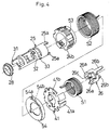
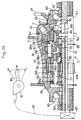
- Fig. 1 is a sectional view of a self-contained change speed apparatus for providing seven speeds.
- Fig. 1A is a vertical section of Fig. 1 showing details of a structure in which a first sleeve is supported by a guide bush.
- Fig. 1B is a section taken on line P-P of Fig. 1A.
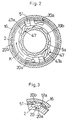
- Fig. 2 is a sectional view taken on a plane perpendicular to a fixed shaft and showing a relationship between a brake clutch and fourth transmission pawls, as seen in a direction from a drive member to a coaster brake.
- Fig. 3 is a fragmentary sectional view of Fig. 2 taken on a plane perpendicular to the fixed shaft and showing a relationship between a fourth transmission pawl and a pawl cage.
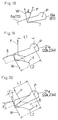
- Fig. 4 is a perspective view of a control member and springs.
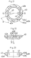
- Fig. 5 is a perspective view of a ball pushing element.
- Fig. 6 is a perspective view of a wire catch.
- Fig. 7 is a perspective view of a rotation restrictor.
- Fig. 8 is a sectional view of the control member showing engagement between a first fork and a second fork.
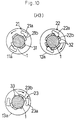
- Fig. 9 is an explanatory view of a sun pawl.
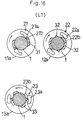
- Fig. 10 is a sectional view taken on a plane perpendicular to the fixed shaft and showing relations among sun pawls, restrictor projections and control portions in third high-speed positions of sun clutches.
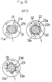
- Fig. 11 is a sectional view taken on the plane perpendicular to the fixed shaft and showing relations among the sun pawls, restrictor projections and control sections in second high-speed positions of the sun clutches.
- Fig. 12 is a sectional view taken on the plane perpendicular to the fixed shaft and showing relations among the sun pawls, restrictor projections and control sections in first high-speed positions of the sun clutches.
- Fig. 13 is a sectional view taken on the plane perpendicular to the fixed shaft and showing relations among the sun pawls, restrictor projections and control sections in intermediate speed positions of the sun clutches.
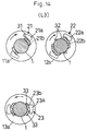
- Fig. 14 is a sectional view taken on the plane perpendicular to the fixed shaft and showing relations among the sun pawls, restrictor projections and control sections in first low-speed positions of the sun clutches.
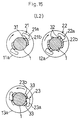
- Fig. 15 is a sectional view taken on the plane perpendicular to the fixed shaft and showing relations among the sun pawls, restrictor projections and control sections in second low-speed positions of the sun clutches.
- Fig. 16 is a sectional view taken on the plane perpendicular to the fixed shaft and showing relations among the sun pawls, restrictor projections and control sections in third low-speed positions of the sun clutches,.
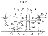
- Fig. 17 is a diagram corresponding to Fig. 1.
- Fig. 18 is a side view of a transmission pawl.
- Fig. 19 is a side view of a sun pawl.
- Fig. 20 is a side view of the sun pawl.
- Fig. 21 is a front view of a clutch operator.
- Fig. 22 is a side view of the clutch operator.
- Fig. 23 is a sectional view of the clutch operator taken on line Q-Q of Fig. 21.
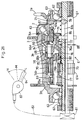
- Fig. 24 is a sectional view of a three-stage change speed apparatus in a high speed state.
- Fig. 25 is a sectional view of the three-stage change speed apparatus in an intermediate speed state.
- Fig. 26 is a sectional view of the three-stage change speed apparatus in a low speed state.
- Fig. 27 is a sectional view showing relations among a second rotatable transmission member, transmission teeth, transmission pawls and a first rotatable transmission member.
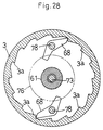
- Fig. 28 is a sectional view showing relations among a hub body, third transmission pawls and a fixed shaft.
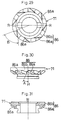
- Fig. 29 is a front view of a first control cam.
- Fig. 30 is a plan view of the first control cam.
- Fig. 31 is a sectional view of the first control cam taken on line R-R of Fig. 29.
- Fig. 32 is a front view of a second control cam.
- Fig. 33 is a plan view, partly in section, of the second control cam.
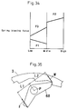
- Fig. 34 is an explanatory view of a spring biasing force.
- Fig. 35 is a front view showing configuration of a third transmission pawl.
- A first embodiment of the present invention will be described hereinafter with reference to the drawings.
- As shown in Fig. 1, a self-contained change speed apparatus according to the present invention, broadly, comprises a fixed
shaft 1 secured to a bicycle frame, and adrive member 2 and ahub body 3 rotatably supported on the fixedshaft 1. Thedrive member 2 has achainwheel 2a, and thehub body 3 hashubs 3a for supporting spokes. A drive transmission line from thedrive member 2 to thehub body 3 includes an accelerating firstplanetary gear mechanism 4 and a decelerating secondplanetary gear mechanism 5. A coaster brake 6 is provided on a side remote from thedrive member 2. As will be described later, the drive transmission line is switchable by a clutch operating mechanism 7, and a tubularclutch control member 8 is rotatably mounted on the fixedshaft 1 for controlling the clutch operating mechanism 7 and for controlling control sections of sun gears to allow or prohibit rotation of sun gears. This embodiment provides seven speed stages as described later. - The two
planetary gear mechanisms second gear carriers first carrier 4a is relatively unrotatably engaged with arelay member 9 disposed adjacent the coaster brake 6. The firstplanetary gear mechanism 4 further includes a first and a second sun gears 11a and 12a. The secondplanetary gear mechanism 5 further includes a third and a fourth sun gears 13a and 14a. The first to fourth sun gears 11a-14a are supported on the fixedshaft 1 to be rotatable independently of one another and axially immovable. The first and second sun gears 11a and 12a, respectively, are meshed with first and second planet gears 11b and 12b, each pair of first and second planet gears being formed integral. The third and fourth sun gears 13a and 14a, respectively, are meshed with third and fourth planet gears 13b and 14b, each pair of third and fourth planet gears being formed integral also. The second planet gears 12b are meshed also with afirst ring gear 15. The fourth planet gears 14b are meshed also with asecond ring gear 16. Selective free wheeling and locking controls of the sun gears 11a, 12a, 13a and 14a relative to the fixedshaft 1 are carried out by theclutch control member 8 as described in detail later. - The
first ring gear 15 andrelay member 9 are selectively used as an output element to act on thehub body 3. Thesecond ring gear 16 andsecond gear carrier 5a are selectively used as an input element to receive drive from thedrive member 2. One-way clutches are employed to effect selective drive transmission between these components. These one-way clutches include afirst transmission clutch 17 provided between therelay member 9 andhub body 3, asecond transmission clutch 18 provided between thefirst ring gear 15 andhub body 3, athird transmission clutch 19 provided between thesecond gear carrier 5a and drivemember 2, and afourth transmission clutch 20 provided between thesecond ring gear 16 and drivemember 2. These one-way clutches also include first to fourthtransmission ratchet pawls teeth transmission pawls transmission teeth first transmission pawls 17a are attached to therelay member 9, thesecond transmission pawls 18a to thefirst ring gear 15, and the third andfourth transmission pawls drive member 2. Thetransmission pawls hub body 3,second gear carrier 5a orsecond ring gear 16 is driven only when the components carrying the pawls are rotated in the direction of arrow K in Fig. 1. Thethird transmission pawls 19a are meshed with thethird transmission teeth 19b over an entire width thereof, and thethird transmission clutch 19 is operable by the clutch operating mechanism 7 described later. - As shown in Figs. 1 and 10 through 17, a first to a
fourth sun clutches shaft 1 and the first to fourth sun gears 11a, 12a, 13a and 14a. Thesesun clutches fourth sun pawls shaft 1, respectively. The fixedshaft 1 defines first and secondrestrictor projections third sun pawls shaft 1. The secondrestrictor projections 22b are used for both the second andthird sun pawls second sun clutches shaft 1, while thethird sun clutch 23 allows rotation in the driving direction K relative to the fixed shaft 1 (as will be readily understood by referring to Figs. 10 through 16). Thefirst sun gear 11a has a small diameter, and includes a portion extending leftward for forming thefirst sun clutch 21. Numeral 24b in Fig. 1 denotes a pawl attaching element as shown in Fig. 24, which is unrotatably mounted on the fixedshaft 1 to form a pawl attaching portion of the fixedshaft 1. - As shown in Figs. 1 and 4, the
clutch control member 8 includes afirst sleeve 25 and asecond sleeve 26 rotatably mounted on the fixedshaft 1 and arranged in order from a position adjacent the coaster brake 6 arid awire catch 27 for engaging a nipple of a control wire C. Thefirst sleeve 25 defines afirst fork 25a extending rightward. Thesecond sleeve 26 defines asecond fork 26a and athird fork 26b extending leftward and rightward, respectively. As shown in Figs. 1A and 1B, thesleeve 25 includes, mounted on an end thereof adjacent the coaster brake 6, aguide bush 28 for reinforcement, i.e. for preventing the end of thesleeve 25 from flexing radially and circumferentially of the fixedshaft 1, and aretainer spring 29 for preventing thesleeve 25 from moving axially of the fixedshaft 1 toward the coaster brake 6. The twosleeves second fork 26a circumferentially of thesleeve 26 and the thickness of a prong of thefirst fork 25a circumferentially of thesleeve 25. Beyond the angle D thesleeves first fork 25a andsecond fork 26a. Acam element 41 is provided to be rotatable with thefirst sleeve 25 through engagement with thefirst fork 25a. A first spring S1 is connected at one end thereof to a spring attaching bore 41b defined in thecam element 41, and the other end to aspring attaching bore 26c defined in thesecond sleeve 26. The first andsecond sleeves first sleeve 25 is rotatable with thesecond sleeve 26 when thesecond sleeve 26 rotates in the direction opposite to the driving direction K, and that thesecond sleeve 26 is rotatable through the predetermined angle D relative to thefirst sleeve 25 when a rotational resistance exceeding a predetermined value is applied to thefirst sleeve 25. Extreme ends of thethird fork 26b are engaged withgrooves 27b formed onprojections 27a extending toward the center from inner peripheral walls of thewire catch 27. Thus, thecontrol member 8 as a whole is rotatable relative to the fixedshaft 1. - A second spring S2 is connected at one end thereof to a spring attaching bore 53 defined in the
pawl attaching element 24b, and the other end to aspring attaching cutout 54a defined in aspring bearing plate 54. Thespring bearing plate 54 also defines aspring attaching bore 54b for engaging the first spring S1. Thus, thespring bearing plate 54 is engaged with thesleeve 25 through the first spring S1 andcam element 41. When theclutch control member 8 rotates in the direction opposite to the driving direction K, the second spring S2 is wound by thesleeve 25, thereby biasing thesleeve 25 to rotate backward in the driving direction K. - The springs S1 and S2 are formed as torsion coil springs to produce an elastic restoring force as a result of torsion. These springs S1 and S2 are mounted on the fixed
shaft 1 to be inside the change speed apparatus. - The
sun gear clutches first sleeve 25. As shown in Fig. 4, thefirst sleeve 25 includes afirst control section 31, asecond control section 32 and athird control section 33. As shown in Figs. 10 through 16, these control sections may be combined with the first and secondrestrictor projections third sun pawls third sun gears shaft 1, and to prevent engagement between therestrictor projections third sun pawls third control sections restrictor projections third sun pawls shaft 1. Then the first tothird sun pawls restrictor projections third sun gears fourth sun clutch 24 requires no control. - As shown in Fig. 1, the
wire catch 27 is mounted between aball pushing element 34 as shown in Fig. 5 and arotation restrictor 35 as shown in Fig. 7. The rotation restrictor 35 contacts theprojections 27a to limit angles of rotation of thecontrol member 8 within a predetermined range. Theball pushing element 34 androtation restrictor 35 are engaged with a fixinggroove 1a defined on the fixedshaft 1 not to be rotatable relative thereto. Numeral 36 in Fig. 1 denotes a retainer nut for maintaining the various components in place. Balls are mounted between theball pushing element 34 and drivemember 2 and between thedrive member 2 andhub body 3 to allow relative rotation. - As shown in Fig. 1, the clutch operating mechanism 7 includes a
clutch operator 40 for raising thethird transmission pawls 19a by means of the biasing force into engagement with thecarrier 5a to engage thethird transmission clutch 19 and for turning thethird transmission pawls 19a toward thedrive member 19 away from thecarrier 5a to disengage thethird transmission clutch 19, a fixedplate 42 for axially movably supporting theclutch operator 40, and theannular cam element 41 unrotatably engaging thefirst fork 25a and rotatably fitted inside the fixedplate 42. The fixedplate 42 is engaged with the fixinggroove 1a not to be rotatable relative to the fixedshaft 1. Theclutch operator 40 has inner peripheries thereof fitted to the fixedplate 42, whereby theclutch operator 40 is not rotatable relative to the fixedshaft 1. Thecam element 41, as shown in Fig. 4, includes afork 41a which receives, between prongs thereof, pins 43 extending inwardly from the fixedplate 42 of theclutch operator 40 to transmit torque from theclutch control member 8 to thepins 43 to rotate theclutch operator 40. Thecam element 41 is contactable through the fixedplate 42 by theball pushing element 34 to be limited in rightward movement. When heads of thepins 43 press fit in theclutch operator 40 and acting as cam followers are pushed, theclutch operator 40 moves leftward. Theclutch operator 40 includescontrol portions 40K as shown in Figs. 21 and 22 for contacting thethird transmission pawls 19a. Thecontrol portions 40K include afirst contact 40a for contacting thethird transmission pawls 19a and raising and reclining these pawls to outer peripheries of theclutch operator 40, and asecond contact 40b for contacting thethird transmission pawls 19a and maintaining the these pawls in the reclined position. Theclutch operator 40 is urged to return rightward by acompression spring 44. - The coaster brake 6 is operable when the
drive member 2 rotates backward to rotate thegear carriers drive member 2 andsecond gear carrier 5a. The coaster brake 6 includesbrake shoes 48 arranged annularly and opposed to a braking insidesurface 3b of thehub body 3, a plurality ofrollers 49 arranged on inside surfaces of thebrake shoes 48, and cam surfaces formed on thefirst gear carrier 4a for radially outwardly pushing therollers 49 when thefirst gear carrier 4a rotates backward. - As shown in Figs. 1 through 3, the
brake clutch 47 includesbraking ratchet pawls 47a and thethird transmission teeth 19b. Thebraking pawls 47a are constantly spring-loaded toward thethird transmission teeth 19b, and oriented in an opposite direction to thethird transmission clutch 19. Thefourth transmission pawls 20a project toward thefourth transmission teeth 20b throughcutouts 51a formed in anannular pawl cage 51. Thepawl cage 51 includes portions thereof extending to proximal ends of thebraking pawls 47a. The proximal ends of thebraking pawls 47a are movable relative to thedrive member 2 when thebraking pawls 47a are engaged with thethird transmission teeth 19b. The movement of these proximal ends moves thecage 51 and thecutouts 51a relative to thedrive member 2 through the projecting pieces, thereby to recline thefourth transmission pawls 20a to disengage thefourth transmission clutch 20. Consequently, the coaster brake 6 is operable through thebrake clutch 47 andgear carriers drive member 2 rotates backward, without interference by thefourth transmission clutch 20 andbrake clutch 47. Numeral 52 in Fig. 1 denotes a torsion spring for urging thepawl cage 51 back to a position to place thefourth transmission clutch 20 in an operable position. - When, for example, the cyclist pushes the bicycle backward to rotate the rear wheel backward, backward rotation of the
hub body 3 is transmitted to thedrive member 2 through the planetary gear mechanisms and the fourtransmission pawls 20a. The backward rotation of thedrive member 2 operates thebraking pawls 47a to disengage thefourth transmission pawls 20a. As a result, thedrive member 2 is stopped rotating backward to render thebraking pawls 47a inoperable. Since thebraking pawls 47a are inoperable, thefourth transmission pawls 20a rotate thedrive member 2 backward again. When this is repeated, the bicycle cannot be pushed backward smoothly and noise is produced. To solve this problem, aslide spring 16a is provided for thesecond ring gear 16. A detailed description of theslide spring 16a is given next. - As shown in Fig. 1D, the
slide spring 16a is substantially circular in shape except for an end portion that is bent toward the center of the circle. The tip of the end portion is further bent so that the tip is perpendicular to the plane of the circle. As can be seen in Fig. 1C, this tip is inserted into a receiving hole formed in thedrive member 2 so that theslide spring 16a and thedrive member 2 rotates in unison. Theslide spring 16a also has an unbent end (unnumbered) as seen in Fig. 1D. - The circular portion of the slide spring is slidably received in a groove formed in the
second ring gear 16 as sectionally shown in Fig. 1C. Theslide spring 16a needs to be squeezed into the groove which has a smaller diameter than the diameter of the circle of the spring so that theslide spring 16 exerts a frictional force against the surface of the groove. Fig. 1D shows the orientation of theslide spring 16a when placed in thesecond ring gear 16 as viewed in the axial direction toward the coaster brake 6. - When the
ring gear 16 rotates, in the direction opposite to the driving direction K, as does when the bicycle operator pushes the bicycle backwards, the friction between theslide spring 16a and the groove formed in thesecond ring gear 16 urges theslide spring 16a to rotate in the same direction. This urges the gap between the two ends of the slide spring to expand which increases the radially outward force of thespring 16a against the groove. This, in turn, causes the friction force between the groove and the slide spring to increase, rotating thedrive member 2 in unison with thering gear 16 as a result. - On the other hand, when the second ring gear rotates in the driving direction K, relative to the
drive member 2, that is when thesecond ring gear 16 rotates with greater angular speed than the angular speed of thedrive member 2, as is the case when the driving motion is transmitted through thethird transmission clutch 19, the friction force between the groove and theslide spring 16a urges the gap between the two ends of the spring to diminish which decreases the radially outward force of the slide spring against the groove to decrease. This, in turn, decrease the friction force allowing thering gear 16 to rotate independently from thedrive member 2. - The above described structure eliminates the noise problem and the problem of uneven rearward motion since the
drive member 2 rotates with thesecond ring gear 16 in unison when the bicycle is pushed backwards which effectively avoids the unwanted engagement and disengagement of the breakingpawls 47a without resorting to an elaborate structure such as a clutch pawl and clutch teeth. - Reference is now made to Table 1 and the drawings for describing switching of the drive transmission system, basic operations for controlling the sun gears 11a, 12a, 13a and 14a effected through the first
planetary gear mechanism 4 and secondplanetary gear mechanism 5, respectively, and switching of the first to seventh speeds. In Table 1, the sign "-" signifies states in which the one-way clutches 17-24 are inoperative and relative rotation thereof is allowed, which are hereinafter referred to as "inoperative" states. The sign "O" signifies states in which the relative rotation of the one-way clutches is prohibited, which are hereinafter referred to as "engaged" states. The sign "X" signifies states in which engagement of the one-way clutches is prevented to allow the relative rotation thereof, which are hereinafter referred to as "disengaged" states. The clutches without the "X" sign require no external controls. To facilitate understanding, Fig. 17 shows a diagram of the foregoing construction.Table 1 speeds clutch controls 17 18 19 20 21 22 23 24 H3 - O O - - O - - H2 - O O - O X - - H1 - O X O - O O - M - O X O - O X O L1 - O X O O X X O L2 O - X O X X O - L3 O - X O X X X O - In the accelerating type first
planetary gear mechanism 4, thefirst ring gear 15 has a greater angular velocity than therelay member 9 whenever one of the first andsecond sun clutches second transmission clutch 18 is engaged, while thefirst transmission clutch 17 is in the inoperative state. The drive transmission line then becomes an accelerating line extending from thefirst ring gear 15 through thesecond transmission clutch 18 to thehub body 3. On the other hand, when both the first andsecond sun clutches second transmission clutch 18 becomes inoperative. Then the drive transmission line forms a direct line extending from therelay member 9 through thefirst transmission clutch 17 to thehub body 3. Thus, in the firstplanetary gear mechanism 4, the drive transmission line is switchable only by controlling the first andsecond sun clutches second transmission clutches - In the decelerating type second
planetary gear mechanism 5, when thethird transmission clutch 19 is engaged, a direct drive transmission line is formed to extend from thedrive member 2 through thethird transmission clutch 19 to thegear carrier 5a. On the other hand, when thethird transmission clutch 19 is disengaged by the action of the clutch operating mechanism 7, the drive transmission line becomes a decelerating line extending from thedrive member 2 through thefourth transmission clutch 20 andsecond ring gear 16 to thegear carrier 5a. Thus, in the secondplanetary gear mechanism 5, the drive transmission line is switchable only by controlling the clutch operating mechanism 7. - Change speed is effected by pulling the control wire C to rotate the
clutch control member 8 stepwise in the direction opposite to the driving direction K. This operation controls the first to third control sections 31-33 and clutch operating mechanism 7, which in turn control the sun clutches 21-23 andthird transmission pawls 19a. Based on the above rules, seven speeds are successively provided in the accelerating direction from the slowest, third low speed L3 to the fastest, third high speed H3. On the other hand, deceleration is effected by relaxing the control wire C to return theclutch control member 8 under the restoring force of the second spring S2 in the driving direction K, whereby the seven speeds are provided from the fastest, third high speed H3 to the slowest, third low speed L3. Figs. 10 through 16 show positions of the first to third sun clutches 21-23 corresponding to the respective stages from the fastest, third high speed H3 to the slowest, third low speed L3. - Specifically, a shift lever type
manual speed controller 60 is operable through the control wire C to rotate theclutch control member 8. The rotation of theclutch control member 8 slides theclutch operator 40 to produce the following conditions:- - When the
third transmission clutch 19 andsecond sun clutch 22 are engaged and the first andthird sun clutches fourth sun clutch 24 and the first andfourth transmission clutches second transmission clutch 18 engaged. This produces the third high speed H3 in which the torque of thedrive member 2 is transmitted to thehub body 3 through thethird transmission clutch 19,carrier 5a,carrier 4a,first ring gear 15 andsecond transmission clutch 18. - When the
third transmission clutch 19 andfirst sun clutch 21 are engaged, thesecond sun clutch 22 disengaged and the third sun clutch 23 in the inoperative state, thefourth sun clutch 24 and the first andfourth transmission clutches second transmission clutch 18 engaged. This produces the second high speed H2 in which the torque of thedrive member 2 is transmitted to thehub body 3 through thethird transmission clutch 19,carrier 5a,carrier 4a,first ring gear 15 andsecond transmission clutch 18. - When the
third transmission clutch 19 is disengaged, the second andthird sun clutches first sun clutch 21 in the inoperative state, thefourth sun clutch 24 andfirst transmission clutch 17 are inoperative and the second andfourth transmission clutches drive member 2 is transmitted to thehub body 3 through thefourth transmission clutch 20,second ring gear 16,carrier 5a,carrier 4a,first ring gear 15 andsecond transmission clutch 18. - When the
third transmission clutch 19 andthird sun clutch 23 are disengaged, thefirst sun clutch 21 in the inoperative state and thesecond sun clutch 22 engaged, thefourth sun clutch 24 and the second andfourth transmission clutches first transmission clutch 17 in the inoperative state. This produces the intermediate speed M in which the torque of thedrive member 2 is transmitted to thehub body 3 through thefourth transmission clutch 20,carrier 5a,carrier 4a andsecond transmission clutch 18. - When the
third transmission clutch 19 and the second andthird sun clutches first sun clutch 21 engaged, thefourth sun clutch 24 and the second andfourth transmission clutches first transmission clutch 17 in the inoperative state. This produces the first low speed L1 in which the torque of thedrive member 2 is transmitted to thehub body 3 through thefourth transmission clutch 20,second ring gear 16,carrier 5a,carrier 4a,first ring gear 15 andsecond transmission clutch 18. - When the
third transmission clutch 19 and the first andsecond sun clutches fourth sun clutch 24 andsecond transmission clutch 18 are in the inoperative state and the first andfourth transmission clutches drive member 2 is transmitted to thehub body 3 through thefourth transmission clutch 20,second ring gear 16,carrier 5a,carrier 4a,relay member 9 andfirst transmission clutch 17. - When the
third transmission clutch 19 and the first, second andthird sun clutches fourth sun clutch 24 and the first andfourth transmission clutch second transmission clutch 18 in the inoperative state. This produces the third low speed L3 in which the torque of thedrive member 2 is transmitted to thehub body 3 through thefourth transmission clutch 20,second ring gear 16,carrier 5a,carrier 4a,relay member 9 andfirst transmission clutch 17. - As shown in Table 1 and Figs. 10 through 16, acceleration and deceleration accompany switching from erected position to reclined position of the
third transmission pawls 19a and thesun pawls drive member 2, transmission loads act on thetransmission pawls 19a and thesun pawls transmission pawls 19a and thesun pawls gear carrier 5a and fixedshaft 1, respectively. This resistance to disengagement is varied among the pawls to be reclined. However, the operating forces are applied from the springs S1 and S2 to theclutch control member 8 andclutch operator 40, and a torque equalizing device is provided for substantially equalizing maximum drive torques applied when any of thetransmission pawls 19a and thesun pawls - Specifically, for change speed in the accelerating direction, the first spring S1 connects the
first sleeve 25 andclutch operator 40 to thesecond sleeve 20 rotated by operation of thespeed controller 60. When the resistance to disengagement of thetransmission pawls 19a and thesun pawls gear carrier 5a and fixedshaft 1 is less than the resilience of the first spring S1, the first spring S1 overcomes the resistance to disengagement, and rotates or slides thefirst sleeve 25 andclutch operator 40 immediately upon rotation of thesecond sleeve 26. In this way, thefirst sleeve 25 reclines thesun pawls clutch operator 40 reclines thetransmission pawls 19a. When the resistance to disengagement of thetransmission pawls 19a and thesun pawls gear carrier 5a and fixedshaft 1 is greater than the resilience of the first spring S1, the first spring S1 is elastically deformed by the resistance to disengagement, the rotating force of thesecond sleeve 26 applied manually, the allowance provided by the predetermined angle D between thesleeves speed controller 60 in a selected speed position. Consequently, the first spring S1 just charges the operating force to be applied to thefirst sleeve 25 andclutch operator 40. Thefirst sleeve 25 andclutch operator 40 remain inoperative and maintain thetransmission pawls 19a and thesun pawls speed controller 60. When the crank being turned reaches or approaches an upper dead point or a lower dead point to reduce the drive torque applied to thedrive member 2, the resistance to disengagement of thetransmission pawls 19a and thesun pawls gear carrier 5a and fixedshaft 1 becomes weaker than the resilience of the first spring S1. Then, the first spring S1, with the operating force charged therein, rotates or slides thefirst sleeve 25 andclutch operator 40. As a result, thefirst sleeve 25 reclines thesun pawls clutch operator 40 reclines thetransmission pawls 19a. - For change speed in the decelerating direction, the second spring S2 rotates or slides the
first sleeve 25 andclutch operator 40 with an elastic restoring force charged therein when the second spring S2 is wound at a time of acceleration. When the resistance to disengagement of thetransmission pawls 19a and thesun pawls gear carrier 5a and fixedshaft 1 is less than the resilience of the second spring S2, the second spring S2 overcomes the resistance to disengagement, and rotates or slides thefirst sleeve 25 andclutch operator 40 immediately upon rotation of thesecond sleeve 26. In this way, thefirst sleeve 25 reclines thesun pawls clutch operator 40 reclines thetransmission pawls 19a. When the resistance to disengagement of thetransmission pawls 19a and thesun pawls gear carrier 5a and fixedshaft 1 is greater than the resilience of the second spring S2, the second spring S2 is prevented from being elastically restored fully through a predetermined stroke by the resistance to disengagement, relaxation of the control wire C, and the action of the speed control device R to retain thespeed controller 60 in a selected speed position. Consequently, the second spring S2 just charges the operating force to be applied to thefirst sleeve 25 andclutch operator 40. Thefirst sleeve 25 andclutch operator 40 remain inoperative and maintain thetransmission pawls 19a and thesun pawls speed controller 60. When the crank being turned reaches or approaches the upper dead point or lower dead point to reduce the drive torque applied to thedrive member 2, the resistance to disengagement of thetransmission pawls 19a and thesun pawls gear carrier 5a and fixedshaft 1 becomes weaker than the resilience of the second spring S2. Then, the second spring S2 elastically restores itself fully through the predetermined stroke, and rotates or slides thefirst sleeve 25 andclutch operator 40. As a result, thefirst sleeve 25 reclines thesun pawls clutch operator 40 reclines thetransmission pawls 19a. - The first spring S1 and second spring S2 produces another effect as follows. When, for example, the
first control section 31 and firstrestrictor projections 21b are not in perfect register, the sun pawls 21 do not fully engage the firstrestrictor projections 21b. The engagement between thesun pawls 21a and firstrestrictor projections 21b would remain imperfect if there were no springs S1 and S2 and thefirst control section 31 did not yield to the engaging force of thesun pawls 21a when the drive torque increases. However, in the presence of springs S1 and S2, thesun pawls 21a, with an increase in the drive torque, push thefirst control section 31 against the resilience of the springs S1 and S2, to fully engage the firstrestrictor projections 21b. This assures stability of engagement. - As factors for equalizing as much as possible the torques applied to the clutch pawls as a result of the drive from the pedals, Figs. 18 through 23 show a first arm length L1, a second arm length L2, an angle of pawl inclination X, an overlap angle Y, a cam angle Z, a first inclination angle A and a second inclination angle B.
- The cam angle Z is applicable to the
transmission pawls 19a, which is a relative angle between resistance W to disengagement of thecarrier 5a and reclining force F of theclutch operator 40. The reclining force F is determined from the first inclination angle A and second inclination angle B of control cam surfaces 40a of theclutch operator 40 as shown in Figs. 21 through 23 which act on thetransmission pawls 19a. The cam angle Z is variable with variations of the first inclination angle A and second inclination angle B. The first inclination angle A is an angle at which theclutch operator 40 sliding axially of the fixedshaft 1 applies camming action to thetransmission pawls 19a. The second inclination angle B is an angle at which camming action is applied to thetransmission pawls 19a rotating relative to theclutch operator 40. - The first arm length L1, second arm length L2, angle of pawl inclination X and overlap angle Y are applicable to the
sun pawls - The first arm length L1 is a distance between a pivotal axis P of erection and reclination and a point at which the reclining force F of the
clutch operator 40 is applied. The second arm length L2 is a distance between the pivotal axis P and a point at which the resistance W to disengagement of the fixedshaft 1 is applied. The operating force required to recline the pawls is variable with variations in the ratio between the first arm length L1 and second arm length L2 even when the resistance to reclination of the sun pawls is constant. - The pawl inclination angle X shows an angle of inclination of the sun pawls relative to the fixed
shaft 1. The larger the pawl inclination angle X is, the greater the resistance to disengagement of the pawl is even when the transmission load is constant. The overlap angle Y shows a degree of overlapping between a locus of movement of a distal end of the pawl and a ratchet portion of the fixedshaft 1. The larger the overlap angle Y is, the greater the resistance to disengagement of the pawl is even when the transmission load is constant. Thus, the operating force required to recline the pawls is variable with variations in the pawl inclination angle Y and overlap angle Y. - That is, even when the drive torque is constant, the resistance of the transmission pawls 19 and
sun pawls carrier 5a and fixedshaft 1 varies from pawl to pawl. The reclining forces of the springs S1 and S2 are variable with target speeds to be produced. However, by suitably setting the cam angle Z, ratio between the first arm length L1 and second arm length L2, overlap angle Y and pawl inclination angle X of thetransmission pawls 19a and sunpawls transmission pawls 19a and sunpawls - As shown in Figs. 9 (a)-(c), each of the
sun pawls sun gear restrictor projections shaft 1. Further, the main pawl body T includes a reclining control section G formed laterally of the distal end T2 for contacting thecontrol section first sleeve 25. The reclining control section G and main pawl body T are displaced in the direction parallel to the axis P of erection and reclination to facilitate setting a desired ratio between the first arm length L1 and second arm length L2. - A second embodiment of the present invention will be described next.
- Referring to Fig. 24, a self-contained change speed apparatus for a bicycle is constructed to provide three speeds, and comprises a fixed
shaft 61 unrotatably secured to a bicycle frame (not shown), and adrive member 2 and ahub body 3 rotatably supported on the fixedshaft 1 throughball pushing elements 62 andballs 63. Thedrive member 2 receives drive from achainwheel 2a, and transmits torque to thehub body 3 in three speeds, i.e. high, intermediate and low speeds, through a main apparatus portion including a first to a fourth transmission pawls 66-69 and planet gears 70. This change speed apparatus includes a change speed control mechanism E having afirst control cam 71, asecond control cam 72 and acontrol rod 73 for switching the main apparatus portion to effect change speed. Details of this construction are as follows. - The main apparatus portion includes a first
rotatable transmission member 74, acarrier 75 and a second rotatable transmission member 7 rotatably mounted on the fixedshaft 61 and drivemember 2;first transmission pawls 66 disposed between thedrive member 2 and firstrotatable transmission member 74;second transmission pawls 67 disposed between thedrive member 2 and secondrotatable transmission member 76;third transmission pawls 68 disposed between therotatable transmission member 74 andhub body 3; theplanetary gears 70 attached to thecarrier 75; andfourth transmission pawls 69 disposed between thecarrier 75 andhub body 3. - As shown in Fig. 27, the
first transmission pawls 66 are attached to outer peripheries of thedrive member 2 to be revolvable with rotation of thedrive member 2 and pivotable between an erected position and a reclined position. Thefirst transmission pawls 66 are in the form of ratchet pawls biased by apawl spring 66a to the erected position with distal ends thereof engaging drivenratchet teeth 74a of the firstrotatable transmission member 74. A difference in rotating rate between thedrive member 2 and firstrotatable transmission member 74 automatically switches thefirst transmission pawls 66 between the erected, driving position and reclined, non-driving position. In the erected position thefirst transmission pawls 66, under the biasing force, engage theratchet teeth 74a to transmit torque from thedrive member 2 to the firstrotatable transmission member 74. In the reclined position thefirst transmission pawls 66 are pushed by theratchet teeth 74a away from the firstrotatable transmission member 74 to allow rotation of thereof relative to thedrive member 2. - The
second transmission pawls 67, as also shown in Fig. 27, are attached to inner peripheries of thedrive member 2 to be revolvable with rotation of thedrive member 2 and pivotable between an erected position and a reclined position. In the erected position thesecond transmission pawls 67 have distal ends thereof engagingtransmission teeth 76a of the secondrotatable transmission member 76 to transmit torque from thedrive member 2 to the secondrotatable transmission member 76. In the reclined position the distal ends of thesecond transmission pawls 67 are disengaged from the secondrotatable transmission member 76 to break torque transmission from thedrive member 2 to the secondrotatable transmission member 76. Thesecond transmission pawls 67 are biased by apawl spring 67a to return to the erected position automatically. The secondrotatable transmission member 76 is rotatably mounted on the fixedshaft 61, and engaged with thecarrier 75 for unitary rotation throughtransmission teeth 76b formed at an end remote from thetransmission teeth 76a. Theplanetary gears 70 are pivotally connected to thecarrier 75 to be rotatable about a mountingaxis 77 and revolvable about an axis of thecarrier 75 with rotation of thecarrier 75. Theplanetary gears 70 are also meshed with asun gear portion 61a of the fixedshaft 61. The firstrotatable transmission member 74 is meshed with theplanetary gears 70 through aninternal gear 74b formed at an end thereof remote from theratchet teeth 74a. When thesecond transmission pawls 67 are erected, the torque of thedrive member 2 is transmitted to the secondrotatable transmission member 76, and the torque of thecarrier 75 is transmitted to the firstrotatable transmission member 74 as accelerated by the planetary gears 70. At this time, the firstrotatable transmission member 74 rotates faster than thedrive member 2 by the accelerating action of theplanetary gears 70 and reclination of thefirst transmission pawls 66. When thesecond transmission pawls 67 are reclined, the torque of thedrive member 2 is transmitted to the firstrotatable transmission member 74 through thefirst transmission pawls 66, and the torque of the firstrotatable transmission member 74 is transmitted to thecarrier 75 as decelerated by the planetary gears 70. - As shown in Fig. 28, the
third transmission pawls 68 are attached to the firstrotatable transmission member 74 throughpivotal axes 78 to be revolvable with rotation thereof and pivotable between an erected position and a reclined position. In the erected position thethird transmission pawls 68 have distal ends thereof engagingtransmission teeth 3a of thehub body 3 to transmit torque from the firstrotatable transmission member 74 to thehub body 3. In the reclined position, the distal ends of thethird transmission pawls 68 are disengaged from thehub body 3 to break the torque transmission from the firstrotatable transmission member 74 to thehub body 3. Thethird transmission pawls 68 are biased by apawl spring 68a to return to the erected position automatically. - The
fourth transmission pawls 69 are attached to thecarrier 75 to be revolvable with rotation thereof and pivotable between an erected position and a reclined position. Thefourth transmission pawls 69 are in the form of ratchet pawls biased by apawl spring 69a to the erected position with distal ends thereof engaging drivenratchet teeth 3b of thehub body 3. A difference in rotating rate between thecarrier 75 andhub body 3 automatically switches thefourth transmission pawls 69 between the erected, driving position and reclined, non-driving position. In the erected position thefourth transmission pawls 69, under the biasing force, engage theratchet teeth 3b to transmit torque from thecarrier 75 to thehub body 3. In the reclined position thefourth transmission pawls 69 are pushed by theratchet teeth 3b away from thehub body 3 to allow rotation of thereof relative to thecarrier 75. - Thus, by switching the
second transmission pawls 67 andthird transmission pawls 68 between the erected position and reclined position, the first andfourth transmission pawls planetary gears 70, provides the three speeds, i.e. the high, intermediate and low speeds, of transmission from thedrive member 2 to thehub body 3, as shown in Table 2 set out hereinafter. - Specifically, when the
second transmission pawls 67 andthird transmission pawls 68 are both erected, the torque of thedrive member 2 is transmitted to thehub body 3 through thesecond transmission pawls 67, secondrotatable transmission member 76,carrier 75,planetary gears 70, firstrotatable transmission member 74 andthird transmission pawls 68. This state produces the high speed. - When the
second transmission pawls 67 are reclined and thethird transmission pawls 68 are erected, the torque of thedrive member 2 is transmitted to thehub body 3 through thefirst transmission pawls 66, firstrotatable transmission member 74 andthird transmission pawls 68. This state produces the intermediate speed. - When the
second transmission pawls 67 andthird transmission pawls 68 are both reclined, the torque of thedrive member 2 is transmitted to thehub body 3 through thefirst transmission pawls 66, firstrotatable transmission member 74,planetary gears 70,carrier 75 andfourth transmission pawls 69. This state produces the low speed. - The change speed control mechanism E includes the
first control cam 71 for controlling thesecond transmission pawls 67, thesecond control cam 72 for controlling thethird transmission pawls 68, a coiltype feed spring 79 disposed between thefirst control cam 71 andball pushing element 62, a coiltype return spring 80 disposed between thesecond control cam 72 andsun gear portion 61a, thecontrol rod 73 mounted inside the fixedshaft 61, and aspeed controller 83 operatively connected to thecontrol rod 73 through an interlockingmechanism 81 and acontrol wire 82. Thespeed controller 84 includes ashift lever 84 operable to slide thecontrol rod 73 to produce a selected speed. - The
first control cam 71 is mounted on the fixedshaft 61 to be slidable axially thereof and not to be rotatable relative thereto by arotation stopper 85. Thefirst control cam 71 is slidable between a pawl erecting position as shown in Fig. 24 and a pawl reclining position as shown in Figs. 25 and 26. In the pawl erecting position, thefirst control cam 71 contacts astopper portion 2b of thedrive member 2, with acam surface 86 of thefirst control cam 71, as shown in Fig. 30, separated from thesecond transmission pawls 67 to allow thesecond transmission pawls 67 to be erected by the force of thepawl spring 67a. In the pawl reclining position, thecam surface 86 of thefirst control cam 71 pushes thesecond transmission pawls 67 to the reclined, non-driving position. Therotation stopper 85 is slidable relative to the fixedshaft 61 along a rotationstopper receiving groove 61b formed therein, to allow the sliding movement of thefirst control cam 71. - The
second control cam 72 is defined by a large diameter portion of the secondrotatable transmission member 76. Thesecond control cam 72 is slidable axially of the fixedshaft 61 with sliding movement of the secondrotatable transmission member 76 while in engagement with thecarrier 75. Thesecond control cam 72 is slidable between a pawl erecting position as shown in Figs. 24 and 25 and a pawl reclining position as shown in Fig. 26. In the pawl erecting position, thesecond control cam 72 contacts astopper ring 88 on the fixedshaft 61, with acam surface 87 of thesecond control cam 72, as shown in Fig. 33, separated from thesecond transmission pawls 67 to allow thethird transmission pawls 68 to be erected by the force of thepawl spring 68a. In the pawl reclining position, thecam surface 87 of thefirst control cam 72 pushes thethird transmission pawls 68 to the reclined, non-driving position. - The
return spring 80 biases thesecond control cam 72 to return to the pawl erecting position automatically. Thereturn spring 80 applies to the second control cam 72 a biasing force P1 which is variable, as shown in Fig. 34, with the sliding movement of thesecond control cam 72. Thefeed spring 79 applies a biasing force P2 as shown in Fig. 34 to thefirst control cam 71 to bias thefirst control cam 71 to the pawl reclining position until the main apparatus portion switches from the high speed state to the intermediate speed state. After the main apparatus portion switches from the high speed state to the intermediate speed state, thefeed spring 79 applies a biasing force P3 as shown in Fig. 34 to thesecond control cam 72 to bias thesecond control cam 72 from the pawl erecting position to the pawl reclining position. The biasing force P3 is applied through thefirst control cam 71 contacting thesecond control cam 72, while the biasing force P1 is applied from thereturn spring 79. - As shown in Figs. 24 through 26, when the
shift lever 84 is operated, its operating force is transmitted to thecontrol rod 73 through thecontrol wire 82 andinterlocking mechanism 81. Then thecontrol rod 73 slides inwardly of the fixedshaft 61 for pushing therotation stopper 85 against the force of thefeed spring 79 to switch thefirst control cam 71 and for switching thesecond control cam 72 against the force of thereturn spring 80. Or thecontrol rod 73 slides outwardly of the fixedshaft 61 for allowing thefeed spring 79 to switch the first andsecond control cams speed controller 83 has a shift lever locking function to retain thecontrol rod 73 in a selected position to maintain thefirst control cam 71 in the pawl reclining position or pawl erecting position against the force of thefeed spring 79. - Specifically, referring to Figs. 24 through 26, when the
shift lever 83 is operated to a high speed position H, thecontrol rod 73 is moved to the position shown in Fig. 24. Thecontrol rod 73 then place thefirst control cam 71 in the pawl erecting position to erect thesecond transmission pawls 67, while thereturn spring 80 places thesecond control cam 72 in the pawl erecting position to erect thethird transmission pawls 68. This state produces the high speed. - When the
shift lever 83 is operated to an intermediate speed position M, thecontrol rod 73 is moved to the position shown in Fig. 25. Then thefirst control cam 71 moves to the pawl reclining position under sliding action by the elastic restoring force of thefeed spring 79 and stopping action of thecontrol rod 73, to recline thesecond transmission pawls 67, while thereturn spring 80 places thesecond control cam 72 in the pawl erecting position to erect thethird transmission pawls 68. This state produces the intermediate speed. - When the
shift lever 83 is operated to a low speed position L, thecontrol rod 73 is moved to the position shown in Fig. 26. Thefirst control cam 71 is placed in the pawl reclining position under sliding action by the elastic restoring force of thefeed spring 79 and stopping action of thesecond control cam 72, to recline thesecond transmission pawls 67. Thesecond control cam 72 is placed in the pawl reclining position under sliding action by the elastic restoring force of thefeed spring 79, to recline thethird transmission pawls 68. This state produces the low speed.Table 2 1st cam 2nd cam 2nd pawls 3rd pawls speed erect erect erected erected H recline erect reclined erected I recline recline reclined reclined L - Each of the
cam surface 86 of thefirst control cam 71 and thecam surface 87 of thesecond control cam 72 includes a plurality of first cam surfaces 86a arranged circumferentially of thecontrol cam transmission pawls second cam surface control cam transmission pawls - Each of the first cam surfaces 86a and 87a defines an inclined flat surface having a first inclination angle A with respect to a sliding axis H of the
control cam transmission pawls control cam transmission pawls drive member 2 or the firstrotatable transmission member 74. As thefirst control cam 71 andsecond control cam 72 slide from the respective pawl erecting position to contact thetransmission pawls transmission pawls transmission pawls drive member 2 or the firstrotatable transmission member 74 and the camming action due to the second inclination angle B. Thus, thetransmission pawls control cam - The
spring 79 imparts a pawl operating force to thecontrol cams - Factors for torque equalization include the first inclination angles A and second inclination angles B shown in Figs. 29 through 33 as well as the cam angle Z of the
second transmission pawls 67 as shown in Fig. 18, and a first arm length L1 and asecond arm length 12 of thethird transmission pawls 68 as shown in Fig. 35. - The cam angle Z is a relative angle between resistance W to disengagement due to the engagement between the transmission pawls 67 and
rotatable transmission member 76 and reclining force F of thefirst control cam 71. The cam angle Z is variable with the first inclination angle A and second inclination angle B of thecontrol cam 72. - The first arm length L1 is a distance between a pivotal axis P of erection and reclination and a point at which the reclining force F of the
second control call 72 is applied. The second arm length L2 is a distance between the pivotal axis P and a point at which the resistance W to disengagement due to engagement with thehub body 3 is applied. The operating force required to recline thepawls 68 is variable with variations in the ratio between the first arm length L1 and second arm length L2. - The first cam surfaces 86a of the
first control cam 71 and the first cam surfaces 87a of thesecond control cam 72 have the first inclination angles A and second inclination angles B as set out in Table 3 below. Thus, the first cam surfaces 86a and 87a have different shapes to differentiate efficiency of the sliding force of thefirst control cam 71 being applied as the reclining force to thesecond transmission pawls 67 and efficiency of the sliding force of thesecond control cam 72 being applied to as the reclining force to thethird transmission pawls 68.Table 3 1st angle A 2nd angle B cam surface 86a about 25o about 75o cam surface 87aabout 20o about 40o - Even when a change speed operation is carried out to allow the
feed spring 79 to impart the sliding force to thefirst control cam 71 andsecond control cam 72, thefeed spring 79 does not elastically restore itself to a predetermined position to switch thefirst control cam 71 andsecond control cam 72 to the pawl reclining position if the crank is in a position other than the low drive load position, a drive torque greater than the a predetermined torque is applied to thedrive member 2, and thesecond transmission pawls 67 andthird transmission pawls 68 receive a resistance to disengagement exceeding the resilience of thespring 79. Thefeed spring 79 elastically restores itself to the predetermined position to switch thefirst control cam 71 andsecond control cam 72 to the pawl reclining position when the crank reaches the low drive load position to reduce the drive torque applied to thedrive member 2, and the resistance to disengagement applied to thesecond transmission pawls 67 andthird transmission pawls 68 falls below the resilience of thespring 79. - The maximum driving torques occurring when the transmission pawls 67 and 68 are reclined are substantially the same whichever pawls are reclined, in spite of the difference between a maximum resistance to disengagement for enabling disengagement of the
second transmission pawls 67 from thesecond control cam 72 and a maximum resistance to disengagement for enabling disengagement of thethird transmission pawls 68 from thehub body 3, and in spite of thesame spring 79 applying the operating force to thecontrol cams second transmission pawls 67 andthird transmission pawls 68 and the first inclination angles A and second inclination angles B of thecontrol cams
Claims (11)
- A self-contained change speed apparatus for a bicycle comprising:
a fixed shaft;
a drive member and a hub body rotatably supported on said fixed shaft; and
change speed means interposed between said drive member and said hub body, said change speed means including
a plurality of clutches subjected to a resistance to disengagement corresponding to a drive torque, and
clutch control means having a shiftable first control member, an elastic member for storing a shift of said first control member as energy, and a shiftable second control member operable by said elastic member for operating said clutches;
wherein said second control member shifts to disengage said clutches when said first control member shifts and said elastic member imparts a force greater than said resistance to disengagement for shifting said second control member, and remains stationary when said first control member shifts and said elastic member imparts a force less than said resistance to disengagement, said second control member being shiftable to disengage said clutches only when the force of said elastic member exceeds said resistance to disengagement;
and wherein said clutches are shaped and arranged such that the force of said elastic member for overcoming said resistance to disengagement is substantially the same for all of said clutches. - A self-contained change speed apparatus as claimed in claim 1, wherein said clutches include ratchet pawls movable between an erected position and a reclined position, and teeth engageable with said ratchet pawls.
- A self-contained change speed apparatus as claimed in claim 1, wherein said change speed means is in form of a planetary gear mechanism.
- A self-contained change speed apparatus as claimed in claim 3, wherein one of said clutches is disposed between a sun gear and a fixed shaft, said sun gear being selectively allowed to rotate and prohibited from rotating on said fixed shaft by said clutches including said ratchet pawls attached to said sun gear and said teeth formed on said fixed shaft.
- A self-contained change speed apparatus as claimed in claim 3, wherein one of said clutches is disposed between said planetary gear mechanism and said hub body, drive transmission from said planetary gear mechanism to said hub body being selectively allowed and prohibited by said clutches including said ratchet pawls attached to said planetary gear mechanism and said teeth formed on said hub body.
- A self-contained change speed apparatus as claimed in claim 2, wherein said ratchet pawls are biased by a spring load for engagement with said teeth, said clutch operator being operable to recline said ratchet pawls against said spring load.
- A self-contained change speed apparatus as claimed in claim 2, wherein said ratchet pawls have a first length between an axis of erection and reclination and a point to which a reclining force of said clutch operator is applied, and a second length between said axis of erection and reclination and a point of contact with said teeth, whereby the forces for overcoming said resistance to disengagement are substantially the same for all of said clutches.
- A self-contained change speed apparatus as claimed in claim 7, wherein said ratchet pawls have also a selected angle formed between a straight line extending through said axis of erection and reclination and a plane of contact with said teeth, whereby the forces for overcoming said resistance to disengagement are substantially the same for all of said clutches.
- A self-contained change speed apparatus as claimed in claim 1, wherein said elastic member is formed of a spring.
- A self-contained change speed apparatus as claimed in claim 1, wherein the force of said elastic member for shifting said second control member is greater than said resistance to disengagement adjacent an upper dead point and a lower dead point of pedals.
- A self-contained change speed apparatus as claimed in claim 1, wherein the shift of said first control member is transmitted to said second control member through said elastic member.
Applications Claiming Priority (4)
| Application Number | Priority Date | Filing Date | Title |
|---|---|---|---|
| JP22895691A JP3157205B2 (en) | 1991-09-09 | 1991-09-09 | Bicycle transmission |
| JP03228955A JP3107317B2 (en) | 1991-09-09 | 1991-09-09 | Bicycle transmission |
| JP228955/91 | 1991-09-09 | ||
| JP228956/91 | 1991-09-09 |
Publications (3)
| Publication Number | Publication Date |
|---|---|
| EP0531608A2 true EP0531608A2 (en) | 1993-03-17 |
| EP0531608A3 EP0531608A3 (en) | 1993-04-28 |
| EP0531608B1 EP0531608B1 (en) | 1995-05-24 |
Family
ID=26528560
Family Applications (1)
| Application Number | Title | Priority Date | Filing Date |
|---|---|---|---|
| EP92104800A Expired - Lifetime EP0531608B1 (en) | 1991-09-09 | 1992-03-19 | Self-contained change speed apparatus for a bicycle |
Country Status (3)
| Country | Link |
|---|---|
| US (1) | US5322487A (en) |
| EP (1) | EP0531608B1 (en) |
| DE (2) | DE69202657D1 (en) |
Cited By (18)
| Publication number | Priority date | Publication date | Assignee | Title |
|---|---|---|---|---|
| DE4229023A1 (en) * | 1992-09-01 | 1994-03-10 | Fichtel & Sachs Ag | Shifting device for multi-speed hub |
| EP0658475A1 (en) * | 1993-12-16 | 1995-06-21 | Shimano Inc. | Control system for a working apparatus for use on a bicycle |
| EP0679570A2 (en) * | 1994-04-28 | 1995-11-02 | Shimano Inc. | An internally mounted bicycle transmission using roller clutches |
| EP0693419A2 (en) * | 1994-07-23 | 1996-01-24 | FICHTEL & SACHS AG | Multi-speed hub transmission for a bicycle with more than three speeds |
| EP0803431A2 (en) * | 1996-04-22 | 1997-10-29 | Shimano Inc. | Hub transmission for bicycle |
| EP0803430A2 (en) * | 1996-04-22 | 1997-10-29 | Shimano Inc. | Hub transmission for bicycle |
| EP0805103A2 (en) * | 1996-05-03 | 1997-11-05 | FICHTEL & SACHS AG | Operating device for bicycle multispeed hub |
| WO1998052818A1 (en) * | 1997-05-16 | 1998-11-26 | Bernhard Rohloff | Multispeed bicycle gear system |
| EP0922630A1 (en) * | 1997-12-12 | 1999-06-16 | Shimano Inc. | Bicycle shifting device |
| US6478710B1 (en) | 1999-06-17 | 2002-11-12 | Sram Deutschland Gmbh | Shifting device for a multi-speed hub for a bicycle |
| EP1344714A1 (en) | 2002-03-14 | 2003-09-17 | Shimano Inc. | Hub transmission for a bicycle |
| EP1344715A1 (en) | 2002-03-14 | 2003-09-17 | Shimano Inc. | Hub transmission for a bicycle |
| DE19828829B4 (en) * | 1998-06-27 | 2004-08-05 | Kun Teng Industry Co., Ltd., Ta-Ya Hsiang | Fünfgangnabe |
| DE102004034113A1 (en) * | 2004-07-15 | 2006-02-09 | Sram Deutschland Gmbh | Bicycle hub gearchange with integral brake activated by reverse pedalling and with a control sleeve to inhibit the forward torque drive during reverse braking |
| EP0795460B2 (en) † | 1996-03-15 | 2007-01-17 | Shimano Inc. | Hub bicycle transmission |
| EP1571077A3 (en) * | 2004-03-06 | 2007-07-18 | SRAM Deutschland GmbH | Planetary gear mechanism for a bicycle hub |
| CN108290616A (en) * | 2015-08-28 | 2018-07-17 | 先进技术有限公司 | For the bicycle drive between the sprocket carrier and wheel hub of bicycle and the rear axle equipped with transmission device and trailing wheel |
| WO2019192634A1 (en) * | 2018-03-28 | 2019-10-10 | Wilfried Donner | Multi-speed transmission with two planetary gears |
Families Citing this family (31)
| Publication number | Priority date | Publication date | Assignee | Title |
|---|---|---|---|---|
| DE4415266C1 (en) * | 1994-04-30 | 1995-08-10 | Fichtel & Sachs Ag | Gear change mechanism for multi-speed bicycle hub |
| US5515957A (en) * | 1994-09-08 | 1996-05-14 | Mcconaghy; Robert F. | Uni-directional transmission with positive engagement and disengagement features |
| KR970042080A (en) * | 1995-12-30 | 1997-07-24 | 마재열 | Bicycle drive |
| US5863270A (en) * | 1997-09-15 | 1999-01-26 | Industrial Technology Research Institute | Self-contained change speed apparatus for use on a bicycle |
| WO2000019120A1 (en) | 1998-09-30 | 2000-04-06 | Taylor Anthony G | Redundant freewheeling bicycle apparatus and method |
| US6155394A (en) * | 1999-03-22 | 2000-12-05 | Shook; William B. | Bicycle coasting mechanism |
| DE10014265C5 (en) * | 1999-06-17 | 2012-04-26 | Sram Deutschland Gmbh | Switching device for a multi-speed hub for a bicycle |
| GB2355772A (en) * | 1999-10-30 | 2001-05-02 | Adrian Ash | Bicycle gearbox having a plurality of planetary gear sets in series |
| US6607465B1 (en) * | 2000-03-10 | 2003-08-19 | Shimano, Inc. | Bicycle hub transmission with a guiding member for a sun gear |
| KR200233702Y1 (en) * | 2001-03-27 | 2001-10-18 | 황보연 | Opening device for can |
| DE10118645A1 (en) * | 2001-04-14 | 2002-10-17 | Sram De Gmbh | Initiation and transmission of the shift movement in a bicycle transmission |
| US6558288B2 (en) * | 2001-05-18 | 2003-05-06 | Shimano, Inc. | Internal transmission device with automatic shift mechanism for a bicycle |
| US6641500B2 (en) * | 2001-12-27 | 2003-11-04 | Shimano, Inc. | Bicycle hub transmission with a power control mechanism for a shift assist mechanism |
| KR100479871B1 (en) * | 2003-05-13 | 2005-03-31 | 홍재호 | Front&rear function pedaling unit |
| EP1849699B1 (en) * | 2006-04-28 | 2008-11-26 | Shimano Inc. | Multispeed bicycle hub having back pedal brake |
| JP4346103B2 (en) * | 2006-10-10 | 2009-10-21 | 本田技研工業株式会社 | Magnetostrictive torque sensor |
| US7621842B2 (en) * | 2007-02-14 | 2009-11-24 | Shimano Inc. | Bicycle hub assembly |
| US20080217131A1 (en) * | 2007-03-05 | 2008-09-11 | Gm Global Technology Operations, Inc. | Dual one-way clutch assembly |
| DE102007021970A1 (en) * | 2007-05-10 | 2008-11-13 | Sram Deutschland Gmbh | Bicycle multi-gear hub, with friction clutches, prevents switch sleeve rotation against the pawl on gear selection to reduce wear |
| EP2017175B1 (en) * | 2007-07-18 | 2011-03-16 | Shimano Inc. | Hub transmission for a bicycle |
| US7682283B2 (en) * | 2007-11-20 | 2010-03-23 | Shimano, Inc. | Bicycle hub transmission with a power control mechanism for a shift assist mechanism |
| TWM348027U (en) * | 2008-08-25 | 2009-01-01 | Kun Teng Industry Co Ltd | Left/right driving exchangeable external fixed pawl-type ratchet hub |
| US8376110B2 (en) * | 2010-01-08 | 2013-02-19 | Shimano Inc. | Bicycle hub assembly |
| US8991844B2 (en) * | 2011-07-01 | 2015-03-31 | Radio Flyer Inc. | Multiple configuration tricycle |
| WO2013023311A1 (en) * | 2011-08-17 | 2013-02-21 | Synergy Biosurgical Ag | Device for the propulsion and eccentric braking of a vehicle |
| US9651138B2 (en) | 2011-09-30 | 2017-05-16 | Mtd Products Inc. | Speed control assembly for a self-propelled walk-behind lawn mower |
| USD777607S1 (en) | 2015-03-06 | 2017-01-31 | Radio Flyer Inc. | Folding tricycle |
| US10336394B2 (en) | 2015-06-02 | 2019-07-02 | Radio Flyer Inc. | Foldable tricycle |
| US9789893B2 (en) | 2015-09-29 | 2017-10-17 | Radio Flyer Inc. | Stroller tricycle |
| USD787378S1 (en) | 2016-02-09 | 2017-05-23 | Radio Flyer Inc. | Stroller tricycle |
| NL2021891B1 (en) * | 2018-10-26 | 2020-05-13 | Advancing Tech B V | Transmission system |
Citations (3)
| Publication number | Priority date | Publication date | Assignee | Title |
|---|---|---|---|---|
| GB2136065A (en) * | 1983-02-02 | 1984-09-12 | Fichtel & Sachs Ag | Gear-change device for a multi- ratio cycle hub |
| GB2166503A (en) * | 1984-11-02 | 1986-05-08 | Fichtel & Sachs Ag | Multi-speed gear hub for a bicycle |
| EP0383350B1 (en) * | 1989-02-17 | 1995-06-07 | Shimano Inc. | Change-speed hub |
Family Cites Families (5)
| Publication number | Priority date | Publication date | Assignee | Title |
|---|---|---|---|---|
| US3432013A (en) * | 1966-07-05 | 1969-03-11 | Shimano Industrial Co | Rear hub with built-in three stage speed change mechanism for a bicycle |
| US4437552A (en) * | 1980-10-24 | 1984-03-20 | Canon Kabushiki Kaisha | Spring clutch device |
| JPS5911990A (en) * | 1982-07-09 | 1984-01-21 | 土江 公裕 | Drive for bicycle |
| DE3440067A1 (en) * | 1984-11-02 | 1986-05-07 | Fichtel & Sachs Ag, 8720 Schweinfurt | MULTI-GEAR FOR BICYCLES OR THE LIKE |
| DE3930374A1 (en) * | 1988-10-10 | 1990-04-12 | Fichtel & Sachs Ag | MULTI-SPEED DRIVE HUB WITH MORE THAN THREE GEARS |
-
1992
- 1992-03-19 DE DE69202657A patent/DE69202657D1/en not_active Expired - Lifetime
- 1992-03-19 DE DE69202657T patent/DE69202657T4/en not_active Expired - Lifetime
- 1992-03-19 EP EP92104800A patent/EP0531608B1/en not_active Expired - Lifetime
-
1993
- 1993-08-30 US US08/112,976 patent/US5322487A/en not_active Expired - Lifetime
Patent Citations (3)
| Publication number | Priority date | Publication date | Assignee | Title |
|---|---|---|---|---|
| GB2136065A (en) * | 1983-02-02 | 1984-09-12 | Fichtel & Sachs Ag | Gear-change device for a multi- ratio cycle hub |
| GB2166503A (en) * | 1984-11-02 | 1986-05-08 | Fichtel & Sachs Ag | Multi-speed gear hub for a bicycle |
| EP0383350B1 (en) * | 1989-02-17 | 1995-06-07 | Shimano Inc. | Change-speed hub |
Cited By (35)
| Publication number | Priority date | Publication date | Assignee | Title |
|---|---|---|---|---|
| DE4229023A1 (en) * | 1992-09-01 | 1994-03-10 | Fichtel & Sachs Ag | Shifting device for multi-speed hub |
| US5562563A (en) * | 1993-12-16 | 1996-10-08 | Shimano, Inc. | Control system for a working apparatus for use on a bicycle |
| EP0658475A1 (en) * | 1993-12-16 | 1995-06-21 | Shimano Inc. | Control system for a working apparatus for use on a bicycle |
| US5785625A (en) * | 1994-04-28 | 1998-07-28 | Shimano, Inc. | Internally mounted bicycle transmission using roller clutches |
| EP0679570A3 (en) * | 1994-04-28 | 1996-04-17 | Shimano Kk | An internally mounted bicycle transmission using roller clutches. |
| US5964679A (en) * | 1994-04-28 | 1999-10-12 | Shimano, Inc. | Internally mounted bicycle transmission using roller clutches |
| EP0679570A2 (en) * | 1994-04-28 | 1995-11-02 | Shimano Inc. | An internally mounted bicycle transmission using roller clutches |
| EP0693419A2 (en) * | 1994-07-23 | 1996-01-24 | FICHTEL & SACHS AG | Multi-speed hub transmission for a bicycle with more than three speeds |
| EP0693419A3 (en) * | 1994-07-23 | 1996-03-06 | Fichtel & Sachs Ag | |
| EP0795460B2 (en) † | 1996-03-15 | 2007-01-17 | Shimano Inc. | Hub bicycle transmission |
| EP0803430A2 (en) * | 1996-04-22 | 1997-10-29 | Shimano Inc. | Hub transmission for bicycle |
| EP0803431A3 (en) * | 1996-04-22 | 1998-11-11 | Shimano Inc. | Hub transmission for bicycle |
| EP0803430A3 (en) * | 1996-04-22 | 1998-11-11 | Shimano Inc. | Hub transmission for bicycle |
| US5964678A (en) * | 1996-04-22 | 1999-10-12 | Shimano, Inc. | Internally mounted bicycle transmission |
| EP0803431A2 (en) * | 1996-04-22 | 1997-10-29 | Shimano Inc. | Hub transmission for bicycle |
| EP0805103A3 (en) * | 1996-05-03 | 1998-12-02 | SRAM Deutschland GmbH | Operating device for bicycle multispeed hub |
| US5896969A (en) * | 1996-05-03 | 1999-04-27 | Fichtel & Sachs Ag | Switchable ratchet freewheel for multiple-gear hubs for bicycles |
| EP0805103A2 (en) * | 1996-05-03 | 1997-11-05 | FICHTEL & SACHS AG | Operating device for bicycle multispeed hub |
| WO1998052818A1 (en) * | 1997-05-16 | 1998-11-26 | Bernhard Rohloff | Multispeed bicycle gear system |
| US6258005B1 (en) | 1997-05-16 | 2001-07-10 | Bernhard Rohloff | Multispeed bicycle gear system |
| EP0922630A1 (en) * | 1997-12-12 | 1999-06-16 | Shimano Inc. | Bicycle shifting device |
| CN1098786C (en) * | 1997-12-12 | 2003-01-15 | 株式会社岛野 | Speed variator for bicycle |
| US6312355B1 (en) | 1997-12-12 | 2001-11-06 | Shimano, Inc. | Bicycle transmission that shifts when a driver is in a predetermined rotational position |
| DE19828829B4 (en) * | 1998-06-27 | 2004-08-05 | Kun Teng Industry Co., Ltd., Ta-Ya Hsiang | Fünfgangnabe |
| US6478710B1 (en) | 1999-06-17 | 2002-11-12 | Sram Deutschland Gmbh | Shifting device for a multi-speed hub for a bicycle |
| EP1344715A1 (en) | 2002-03-14 | 2003-09-17 | Shimano Inc. | Hub transmission for a bicycle |
| EP1344714A1 (en) | 2002-03-14 | 2003-09-17 | Shimano Inc. | Hub transmission for a bicycle |
| CZ298101B6 (en) * | 2002-03-14 | 2007-06-20 | Shimano Inc. | Hub transmission for bicycle |
| DE20222009U1 (en) | 2002-03-14 | 2010-09-09 | Shimano Inc., Sakai | Hub gear for a bicycle |
| EP1571077A3 (en) * | 2004-03-06 | 2007-07-18 | SRAM Deutschland GmbH | Planetary gear mechanism for a bicycle hub |
| DE102004034113A1 (en) * | 2004-07-15 | 2006-02-09 | Sram Deutschland Gmbh | Bicycle hub gearchange with integral brake activated by reverse pedalling and with a control sleeve to inhibit the forward torque drive during reverse braking |
| CN108290616A (en) * | 2015-08-28 | 2018-07-17 | 先进技术有限公司 | For the bicycle drive between the sprocket carrier and wheel hub of bicycle and the rear axle equipped with transmission device and trailing wheel |
| CN108290616B (en) * | 2015-08-28 | 2020-11-20 | 先进技术有限公司 | Transmission device between chain wheel bracket and hub of bicycle, rear wheel shaft and rear wheel |
| WO2019192634A1 (en) * | 2018-03-28 | 2019-10-10 | Wilfried Donner | Multi-speed transmission with two planetary gears |
| US11541964B2 (en) | 2018-03-28 | 2023-01-03 | Wilfried Donner | Multi-speed transmission with two planetary gears |
Also Published As
| Publication number | Publication date |
|---|---|
| DE69202657T4 (en) | 2009-09-17 |
| DE69202657D1 (en) | 1995-06-29 |
| US5322487A (en) | 1994-06-21 |
| DE69202657T2 (en) | 1996-01-18 |
| EP0531608B1 (en) | 1995-05-24 |
| EP0531608A3 (en) | 1993-04-28 |
Similar Documents
| Publication | Publication Date | Title |
|---|---|---|
| EP0531608B1 (en) | Self-contained change speed apparatus for a bicycle | |
| US5273500A (en) | Self-contained change speed apparatus for use on a bicycle and having a planetary gear mechanism | |
| US5562563A (en) | Control system for a working apparatus for use on a bicycle | |
| US6258005B1 (en) | Multispeed bicycle gear system | |
| EP3615826B1 (en) | Clutch system for a torque transmission | |
| US6572508B2 (en) | Pawl control mechanism for a bicycle hub transmission | |
| US6641500B2 (en) | Bicycle hub transmission with a power control mechanism for a shift assist mechanism | |
| EP4048581A1 (en) | Transmission system | |
| US8684122B2 (en) | Power assisted bicycle with regenerative function | |
| US20210354783A1 (en) | Transmission system | |
| EP2062810B1 (en) | A bicycle hub transmission with a power control mechanism for a shift assist mechanism | |
| EP0803430B1 (en) | Hub transmission for bicycle | |
| US6692400B2 (en) | Multi-speed gear hub shiftable under load | |
| CN112407135B (en) | Mid-motor capable of multi-gear variable speed adjustment | |
| CN100406341C (en) | An internal hub transmission for a bicycle | |
| US6325739B1 (en) | Bicycle hub transmission with a mechanism for stopping rotation of one or more sun gears relative to another member | |
| JP3157205B2 (en) | Bicycle transmission | |
| US6368243B1 (en) | Bike inner derailleur | |
| JP3107317B2 (en) | Bicycle transmission | |
| CN1807179B (en) | An internal hub transmission for a bicycle and transmission device | |
| KR20030028527A (en) | Synchromesh assembly and Power transmission device with the same | |
| JP3391943B2 (en) | Planetary transmission | |
| KR100223254B1 (en) | Reverse idler gear apparatus in a vehicle |
Legal Events
| Date | Code | Title | Description |
|---|---|---|---|
| PUAI | Public reference made under article 153(3) epc to a published international application that has entered the european phase |
Free format text: ORIGINAL CODE: 0009012 |
|
| PUAL | Search report despatched |
Free format text: ORIGINAL CODE: 0009013 |
|
| AK | Designated contracting states |
Kind code of ref document: A2 Designated state(s): AT BE CH DE DK ES FR GB GR IT LI LU NL SE |
|
| AK | Designated contracting states |
Kind code of ref document: A3 Designated state(s): AT BE CH DE DK ES FR GB GR IT LI LU NL SE |
|
| RBV | Designated contracting states (corrected) |
Designated state(s): DE FR GB IT |
|
| 17P | Request for examination filed |
Effective date: 19930330 |
|
| 17Q | First examination report despatched |
Effective date: 19940429 |
|
| GRAA | (expected) grant |
Free format text: ORIGINAL CODE: 0009210 |
|
| AK | Designated contracting states |
Kind code of ref document: B1 Designated state(s): DE FR GB IT |
|
| ITF | It: translation for a ep patent filed |
Owner name: INTERPATENT ST.TECN. BREV. |
|
| REF | Corresponds to: |
Ref document number: 69202657 Country of ref document: DE Date of ref document: 19950629 |
|
| ET | Fr: translation filed | ||
| PLBE | No opposition filed within time limit |
Free format text: ORIGINAL CODE: 0009261 |
|
| STAA | Information on the status of an ep patent application or granted ep patent |
Free format text: STATUS: NO OPPOSITION FILED WITHIN TIME LIMIT |
|
| 26N | No opposition filed | ||
| REG | Reference to a national code |
Ref country code: GB Ref legal event code: IF02 |
|
| PGFP | Annual fee paid to national office [announced via postgrant information from national office to epo] |
Ref country code: GB Payment date: 20060315 Year of fee payment: 15 |
|
| GBPC | Gb: european patent ceased through non-payment of renewal fee |
Effective date: 20070319 |
|
| PG25 | Lapsed in a contracting state [announced via postgrant information from national office to epo] |
Ref country code: GB Free format text: LAPSE BECAUSE OF NON-PAYMENT OF DUE FEES Effective date: 20070319 |
|
| PGFP | Annual fee paid to national office [announced via postgrant information from national office to epo] |
Ref country code: FR Payment date: 20100324 Year of fee payment: 19 Ref country code: IT Payment date: 20100320 Year of fee payment: 19 |
|
| PGFP | Annual fee paid to national office [announced via postgrant information from national office to epo] |
Ref country code: DE Payment date: 20110316 Year of fee payment: 20 |
|
| REG | Reference to a national code |
Ref country code: FR Ref legal event code: ST Effective date: 20111130 |
|
| PG25 | Lapsed in a contracting state [announced via postgrant information from national office to epo] |
Ref country code: FR Free format text: LAPSE BECAUSE OF NON-PAYMENT OF DUE FEES Effective date: 20110331 |
|
| PG25 | Lapsed in a contracting state [announced via postgrant information from national office to epo] |
Ref country code: IT Free format text: LAPSE BECAUSE OF NON-PAYMENT OF DUE FEES Effective date: 20110319 |
|
| REG | Reference to a national code |
Ref country code: DE Ref legal event code: R071 Ref document number: 69202657 Country of ref document: DE |
|
| REG | Reference to a national code |
Ref country code: DE Ref legal event code: R071 Ref document number: 69202657 Country of ref document: DE |
|
| PG25 | Lapsed in a contracting state [announced via postgrant information from national office to epo] |
Ref country code: DE Free format text: LAPSE BECAUSE OF EXPIRATION OF PROTECTION Effective date: 20120320 |