EP2017175B1 - Hub transmission for a bicycle - Google Patents
Hub transmission for a bicycle Download PDFInfo
- Publication number
- EP2017175B1 EP2017175B1 EP07014097A EP07014097A EP2017175B1 EP 2017175 B1 EP2017175 B1 EP 2017175B1 EP 07014097 A EP07014097 A EP 07014097A EP 07014097 A EP07014097 A EP 07014097A EP 2017175 B1 EP2017175 B1 EP 2017175B1
- Authority
- EP
- European Patent Office
- Prior art keywords
- planetary gear
- hub
- planetary
- carrier
- clutch
- Prior art date
- Legal status (The legal status is an assumption and is not a legal conclusion. Google has not performed a legal analysis and makes no representation as to the accuracy of the status listed.)
- Active
Links
Images


Classifications
-
- B—PERFORMING OPERATIONS; TRANSPORTING
- B62—LAND VEHICLES FOR TRAVELLING OTHERWISE THAN ON RAILS
- B62M—RIDER PROPULSION OF WHEELED VEHICLES OR SLEDGES; POWERED PROPULSION OF SLEDGES OR SINGLE-TRACK CYCLES; TRANSMISSIONS SPECIALLY ADAPTED FOR SUCH VEHICLES
- B62M11/00—Transmissions characterised by the use of interengaging toothed wheels or frictionally-engaging wheels
- B62M11/04—Transmissions characterised by the use of interengaging toothed wheels or frictionally-engaging wheels of changeable ratio
- B62M11/14—Transmissions characterised by the use of interengaging toothed wheels or frictionally-engaging wheels of changeable ratio with planetary gears
- B62M11/16—Transmissions characterised by the use of interengaging toothed wheels or frictionally-engaging wheels of changeable ratio with planetary gears built in, or adjacent to, the ground-wheel hub
-
- B—PERFORMING OPERATIONS; TRANSPORTING
- B62—LAND VEHICLES FOR TRAVELLING OTHERWISE THAN ON RAILS
- B62M—RIDER PROPULSION OF WHEELED VEHICLES OR SLEDGES; POWERED PROPULSION OF SLEDGES OR SINGLE-TRACK CYCLES; TRANSMISSIONS SPECIALLY ADAPTED FOR SUCH VEHICLES
- B62M11/00—Transmissions characterised by the use of interengaging toothed wheels or frictionally-engaging wheels
- B62M11/04—Transmissions characterised by the use of interengaging toothed wheels or frictionally-engaging wheels of changeable ratio
- B62M11/14—Transmissions characterised by the use of interengaging toothed wheels or frictionally-engaging wheels of changeable ratio with planetary gears
- B62M11/18—Transmissions characterised by the use of interengaging toothed wheels or frictionally-engaging wheels of changeable ratio with planetary gears with a plurality of planetary gear units
Definitions
- the present invention relates to a hub transmission for a bicycle.
- a hub transmission comprises a hub axle that is mounted to the bicycle frame.
- the hub axle rotatably supports a driver for transmitting a pedaling force to the hub transmission through a sprocket and a chain.
- the hub transmission further comprises a hub shell which is likewise rotatably supported by the hub axle.
- the hub shell accommodates a power transmission mechanism which is disposed between the driver and the hub shell for transmitting rotational power from the driver to the hub shell.
- the power transmission mechanism provides a plurality of power transmission paths with different gear ratios that can be selected by means of a shift mechanism wherein each power transmission path typically produces a specific gear ratio.
- the power transmission mechanism ordinarily comprises several planetary gear mechanisms.
- the hub transmission according to DE 10 2004 011 052 A1 allows a selection between 9 speed stages which are provided by a plurality of planetary gear mechanisms.
- the known hub transmission comprises three planetary gear mechanisms that allow to combine three speed stages with another five speed stages for a total of nine speed stages with a gear ration of 340%.
- the hub transmission includes a first planetary gear mechanism comprising a first sun gear that is non-rotatably mounted to the hub axle, a first planetary gear rotatably supported by a first planetary gear carrier and a first ring gear.
- the first planetary gears are disposed between the first sun gear and the first ring gear and meshing with the same.
- a second planetary gear mechanism includes a second sun gear which is arranged on the first planetary gear carrier. Second planetary gears are mounted on the first ring gear.
- a third planetary gear mechanism is formed similar to the second planetary gear mechanism and includes a third sun gear mounted on the first planetary gear carrier.
- the third sun gear meshes with third planetary gears each of which are non-rotatably joined to the respective second planetary gears. Thereby a two-step planetary gear is formed.
- the third planetary gears mesh with a second ring gear to transmit the torque of the third planetary gear mechanism to the second planetary gear mechanism.
- the shifting mechanism of this hub transmission comprises a pawl carrier which allows coupling the driver selectively with components of the respective planetary gear mechanisms to produce different gear ratios.
- the pawl carrier comprises a plurality of controllable pawls, namely six pawls that are actuated by means of three shifting cams.
- the arrangement of the two-step planetary gear on the first ring gear in combination with the second ring gear that meshes with the two-step planetary gears leads to a pile type of internal hub transmission. Since the second ring gear overlaps the other components of the three planetary gear mechanisms, the diameter of the second ring gear and, thus, the diameter of the internal hub transmission is increased. Moreover, the pile type construction of the internal hub transmission leads to an increased total weight of the hub.
- the second and third sun gears are each mounted on the first planetary gear carrier. Therefore, the second and third sun gears each rotate together with the first planetary gear carrier around the hub axle.
- the power transmission path for speed stages 8, 9 comprises the driver, the sixth pawl and the first planetary gear carrier wherein the first planetary gears rotate around the first sun gear.
- the power transmission path further comprises the first ring gear, the second ring gear, the first pawl, the pawl connecting the power transmission with the hub shell and the hub shell.
- the third planetary gear rotates around the third sun gear and in speed stage 9 the second planetary gear rotates around the second sun gear.
- a similar hub transmission is known from DE 197 20 796 A1 which discloses a multiple speed hub having a plurality of planetary gear mechanisms arranged in series.
- the hub transmission disclosed therein enables either a 7 speed shifting or a 14 speed shifting.
- the 14 speed hub transmission comprises five planetary gear mechanisms the components of which can be selectively locked to establish the desired power transmission paths.
- a first planetary gear mechanism comprises a first sun gear rotatably supported by a hub axle which can be locked with the same.
- the first sun gear meshes with the smaller diameter of a two-step planetary gear which is rotatably supported by a first planetary gear carrier.
- the first planetary gear carrier is non-rotatably connected with the hub shell.
- the large diameter of the two-step planetary gear meshes with a ring gear that can be locked either with the hub axle or the first sun gear.
- a second planetary gear mechanism comprises a second sun gear rotatably supported by and lockable with the hub axle. Second planetary gears mesh with the sun gear and a second ring gear wherein the second ring gear is non-rotatably connected with the first sun gear.
- a third planetary gear mechanism comprises a third sun gear which is rotatably supported by and lockable with the hub axle.
- Third planetary gears mesh with the third sun gears which are non-rotatably connected with the second planetary gears with the respective second planetary gears.
- the second sun gear meshes with the small diameter stage of the stepped planetary gears, and the third sun gear meshes with the large diameter stage of the stepped planetary gears.
- the fourth and fifth planetary gear mechanisms are similar to the second and third planetary gear mechanisms and are symmetrically formed and arranged.
- the fourth and fifth planetary gear mechanisms therefore likewise comprise two-stage planetary gears wherein the planetary gears of the second and third planetary gear mechanism and the planetary gears of the fourth and fifth planetary gear mechanisms are rotatably supported by means of a common planetary gear carrier.
- the small diameter stage of the stepped planetary gears of the fourth and fifth planetary gear mechanisms mesh with a ring gear that is non-rotatably connected with a driver.
- a further embodiment of the 14-speed hub transmission is based on a modified embodiment of the afore described hub transmission and comprises a second ring gear which meshes with both small diameter stages of the symmetrically arranged stepped planetary gears.
- the common planetary gear carrier is replaced with two separate plantetary gear carriers wherein the planetary gear carrier of the second and third planetary gear mechanisms is non-rotatably connected with the first sun gear.
- the planetary gear carrier of the fourth and fifth planetary gear mechanisms is non-rotatably connected with the driver.
- this object is accomplished by a hub transmission for a bicycle comprising the features of claim 1.
- the invention is based on the idea to provide a hub transmission for a bicycle that comprises a hub axle, a driver and a hub shell each of which are rotatably supported by the hub axle.
- the hub transmission further comprises a power transmission mechanism that is disposed between the driver and the hub shell for transmitting rotational power from the driver to the hub shell through a plurality of power transmission paths and a shift mechanism for selecting one of the plurality of power transmission paths.
- the power transmission mechanism comprises a plurality of planetary gear mechanisms wherein a planetary gear carrier of a downstream planetary gear mechanism meshes with planetary gears of an upstream planetary gear mechanism or with a linking member which is coupled with the planetary gears of the upstream planetary gear mechanism.
- the planetary gear carrier of the downstream planetary gear mechanism is coupled with a brake unit for transmitting a reverse rotational power from the driver to the brake unit.
- the downstream planetary gear mechanism comprises at least a first planetary gear mechanism
- the upstream planetary gear mechanism comprises at least second, third and fourth planetary gear mechanisms.
- a hub transmission structure with an integrated brake unit is known, for example, from EP 1849699 which is owned by the applicant.
- the known hub transmissions lack the specific coupling of the downstream planetary gear carrier with the upstream planetary gear carrier or with the linking member wherein the brake unit is coupled with the downstream planetary gear carrier.
- a hub transmission formed in accordance with the invention has a plurality of advantages. Since the planetary gear carrier of the downstream planetary gear mechanism meshes with planetary gears of the upstream planetary gear mechanism, a compact design is achieved that allows providing a plurality of power transmission paths while maintaining a small diameter of the hub.
- the aforementioned coupling of the downstream planetary gear carrier with upstream planetary gears further allows realizing the plurality of power transmission paths by means of a comparatively simple structure that reduces the risk of a failure of components of the transmission. Due to the surprisingly simple structure of the inventive hub transmission it is possible to produce a hub transmission that enables a comparatively great number of gear ratios at relatively low costs.
- the invention has the further advantage that the planetary gear carrier of the downstream planetary gear mechanism can be coupled with a brake unit to provide a hub transmission with an integrated brake.
- the power transmission mechanism comprises at least four planetary gear mechanisms that are arranged in series. Thereby it is possible to realize a 11-speed hub transmission with a compact design and a relatively small hub diameter.
- the first planetary gear mechanism may comprise the planetary gear carrier of the downstream planetary gear mechanism.
- the third gear mechanism may comprise the planetary gears of the upstream planetary gear mechanism. This means that the first and third planetary gear mechanisms are coupled by means of the downstream or first planetary gear mechanism which meshes with the upstream or third planetary gears.
- the planetary gear carrier of the downstream planetary gear mechanism comprises a carrier portion and a ring gear portion which meshes with the planetary gears of the upstream planetary gear mechanism or with the linking member which is coupled with the planetary gears of the upstream planetary gear mechanism, wherein the carrier portion and the ring gear portion are non-rotatably connected, in particular integrally formed.
- the planetary gear carrier of the downstream planetary gear mechanism fulfils two functions, namely a support function for the planetary gears of the first planetary gear mechanism and a power transmission function for the planetary gears of the upstream planetary gear mechanism.
- the compact design of the hub transmission is optimized. Moreover, it is possible to directly mesh the ring gear portion with the planetary gears of the upstream planetary gear mechanism or alternatively to provide, as an intermediate component between the upstream planetary gear mechanism and the ring gear portion a linking member which is coupled with the planetary gears of the upstream planetary gear mechanism. Thereby, it is possible to use different braking clutch means with the aforementioned embodiments.
- the planetary gear carrier of the downstream planetary gear mechanism is connectable with the fourth planetary gear mechanism.
- the fourth planetary gear mechanism is connectable with the fourth planetary gear mechanism.
- connection of the planetary gear carrier and the downstream planetary gear mechanism with the fourth planetary gear mechanism can be realized, for example, by means of a preferred embodiment wherein the planetary gear carrier of the downstream planetary gear mechanism comprises a clutch engaging portion which is connectable with a planetary gear carrier of the fourth planetary gear mechanism.
- the planetary gear carrier of the downstream planetary gear mechanism is connectable with the hub shell by means of a first clutch.
- the first planetary gear mechanism further comprises a first sun gear rotatably supported by and lockable with the hub axle, a first ring gear coaxially arranged with the first sun gear and a plurality of first planetary gears meshing with the first sun gear and the first ring gear, wherein the first planetary gears are rotatably supported by the planetary gear carrier of the first planetary gear mechanism.
- the first planetary gear mechanism corresponds to the downstream planetary gear mechanism.
- the first ring gear is connectable with the hub shell by a second clutch for transmitting a rotational force from the first ring gear to the hub shell.
- the second planetary gear mechanism comprises a second sun gear rotatably supported by and lockable with the hub axle.
- the second planetary gear mechanism also comprises a second planetary gear carrier rotatably supported relative to the hub axle and a plurality of second planetary gears rotatably supported by the second planetary gear carrier and meshing with the second sun gear.
- the third planetary gear mechanism comprises a third sun gear rotatably supported by and lockable with the hub axle.
- the planetary gears of the third planetary gear mechanism are rotatably supported by the second planetary gear carrier and mesh with the third sun gear.
- the planetary gears of the third planetary gear mechanism and the second planetary gears of the second planetary gear mechanism may be non-rotatably connected, in particular integrally formed to form stepped planetary gears respectively.
- the fourth planetary gear mechanism comprises a fourth sun gear non-rotatably fixed to the hub axle, a second ring gear co-axially arranged with the fourth sun gear and a plurality of fourth planetary gears rotatably supported by a third planetary gear carrier wherein the fourth planetary gears mesh with the fourth sun gear and the second ring gear.
- the third planetary gear carrier can engage with the second planetary gear carrier.
- a third clutch may be disposed between the third planetary gear carrier and the first planetary gear carrier, in particular the clutch engaging portion for transmitting a rotational force from the third planetary gear carrier to the first planetary gear carrier.
- a fourth clutch can be disposed between the driver and the second ring gear for transmitting a rotational force from the driver to the second ring gear.
- a fifth clutch may be disposed between the driver and the third planetary gear carrier for transmitting a rotational force from the driver to the third planetary gear carrier.
- the brake unit comprises a cup which is non-rotatably connected with the hub shell and forms a circumferentially disposed braking surface.
- the brake unit comprises brake elements which are adapted to cooperate with the braking surface for applying a braking torque and control elements for actuating the brake elements.
- the control elements are coupled with the planetary gear carrier of the downstream planetary gear mechanism such that an actuation of the brake elements is effected by a reverse rotation of the planetary gear carrier of the downstream planetary gear mechanism.
- This embodiment provides a reliable and compact brake unit which is coupled with the planetary gear carrier of the downstream planetary gear mechanism to actuate the brake unit. As the planetary gear carrier of the downstream planetary gear mechanism operatively connects the brake unit with the upstream planetary gear mechanism an optimal transmission of the reverse rotational force from the driver to the brake unit is accomplished.
- the first clutch can be disposed between the cup and the planetary gear carrier of the downstream planetary gear mechanism. Thereby it is possible to transmit a forward rotational force from the planetary gear carrier of the downstream planetary gear to the hub shell via the cup which is non-rotatably connected with the hub shell. This arrangement allows to reduce the length of the hub transmission and improves the compact design thereof.
- the first clutch can be supported by a retaining element for the control elements. This embodiment further minimizes the space used for the brake unit.
- control elements comprise a plurality of rollers which cooperate with a plurality of cam surfaces provided on the planetary gear carrier on the downstream planetary gear.
- the retaining element comprises a roller cage supporting the rollers wherein the roller cage is engaged with the planetary gear carrier of the downstream planetary gear mechanism.
- the engagement of the roller cage with the planetary gear carrier of the downstream planetary gear mechanism enables a simple and efficient actuation of the brake units if the planetary gear carrier is rotated in a reverse direction and, thus, also the roller cage.
- the rollers contained in the roller cage cooperate with the cam surfaces such that the rollers push the brake elements against the braking surface for applying a braking torque.
- the fourth clutch can be disposed between the driver and the second ring gear and comprises driving pawls and braking pawls which are adapted to be selectively activated by a forward or reverse rotation of the driver to rotate the second ring gear in a forward or reverse direction.
- Figures 1 to 12 refer to a hub transmission without brake unit to explain the design and function of the gear mechanisms provided in the hub transmission.
- the hub transmission according to Figures 1 and 12 is supplemented in Figures 13 to 17 by a brake unit which is coupled with the most downstream planetary gear mechanism to produce a braking force if the planetary gear mechanism is rotated in a reverse direction.
- the planetary gear mechanisms shown in Figures 1 to 12 and explained in the following in detail correspond to the planetary gear mechanisms of the hub transmissions according to Figures 13 to 17 .
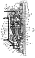
- Fig. 1 illustrates a hub transmission that can be mounted to the rear wheel of a bicycle.
- the hub transmission comprises a hub axle 1 and a driver 2 which is rotatably supported by the hub axle 1.
- the hub transmission further comprises a hub shell 3 which is rotatably supported by hub axle 1.
- a power transmission mechanism 4 is disposed between the driver 2 and the hub shell 3 for transmitting rotational power from driver 2 to the hub shell 3 through a plurality of power transmission paths that can be selected to change the gear ratio as desired by the rider.
- a shift mechanism 5 is provided to select one of the plurality of power transmission paths.
- the shift mechanism 5 corresponds to the shift mechanism which is described in detail in EP 1 323 627 A2 and US 6,607,465 B1 mentioned therein.
- the power transmission mechanism 4 comprises a plurality of planetary gear mechanisms 6, 7, 8, 9 including a downstream planetary gear mechanism and an upstream planetary gear mechanism wherein the upstream planetary gear mechanism is arranged closer to the driver 2 than the downstream planetary gear mechanism.
- the downstream planetary gear mechanism is arranged after the upstream planetary gear mechanism.
- the downstream planetary gear mechanism comprises the first planetary gear mechanism 6
- the upstream planetary gear mechanism comprises the third planetary gear mechanism 8.
- the plurality of planetary gear mechanisms 6, 7, 8, 9 is arranged in series and comprises at least four planetary gear mechanisms 6, 7 ,8, 9.
- the downstream planetary gear mechanism comprises a planetary gear carrier 31, and the upstream planetary gear mechanism comprises planetary gears 43 wherein the planetary gear carrier 31 of the downstream or first planetary gear mechanism 6 meshes with planetary gears 43 of the upstream or third planetary gear mechanism 8.
- the planetary gear carrier 31 has a longitudinally extending shape that is adapted to overlap components of power transmission mechanism 4 that are arranged upstream of the first planetary gear mechanism 6 and, thus, more proximate to the driver 2 than the downstream planetary gear mechanism 6.
- the planetary gear carrier 31 of the downstream planetary gear mechanism 6 axially extends from the area of the downstream or first planetary gear mechanism 6 to the area of the upstream or third planetary gear mechanism 8.
- the planetary gear carrier 31 axially extends over more than 1/3 to 1/2 of the entire length of the hub transmission.
- the axial extension of the planetary gear carrier 31 is such that the second planetary gear mechanism 7 which is arranged between the downstream planetary gear mechanism 6 and the upstream planetary gear mechanism 8 is overlapped by the planetary gear carrier 31.
- the second planetary gear mechanism 7 is not engaged with the planetary gear carrier 31.
- the planetary gear carrier 31 comprises a stepped shape wherein the inner diameter of the subsequent steps increases towards the driver 2.
- the stepped shape of the planetary gear carrier 31 will be described in more detail in conjunction with the respective components associated thereto.
- the planetary gear carrier 31 further comprises a clutch engaging portion 31 c which is arranged on the axial end of the planetary gear carrier 31 proximate to the driver 2.
- the clutch engaging portion 31c is provided to engage with/disengage from a clutch 53 (third clutch) which will be described in more detail in connection with the fourth planetary gear mechanism 9.
- the planetary gear carrier 31 further comprises a ring gear portion 31b.
- the ring gear portion 31b is integrally connected with the clutch engaging portion 31c and is formed with a smaller inner diameter than clutch engaging portion 31c.
- the ring gear portion 31b meshes with planetary gears 43 of the upstream or third planetary gear mechanism 8.
- the inner diameter of the ring gear portion 31b is larger than the outer diameter of second planetary gears 42 of the second planetary gear mechanism 7 to avoid engagement or collision therewith.
- the ring gear portion 31b is integrally connected with a carrier portion 31a which supports first planetary gears 41 of the first downstream planetary gear mechanism 6.
- the first planetary gears 41 are rotatably supported by first planetary gear shafts 41a which are disposed in a carrier portion 31a of the planetary gear carrier 31.
- first planetary gears 41 are provided in the first planetary gear mechanism 6.
- a further clutch engaging portion 31d is integrally formed with the carrier portion 31a and is provided for engaging with/disengaging from a first clutch 51 to establish/interrupt a power transmission from the planetary gear carrier 31 to the hub shell 3.
- a further or second clutch engaging portion 31d is arranged downstream of the planetary gear mechanism 6.
- the ring gear portion 31b and the (first) clutch engaging portion 31c are located upstream of the planetary gear mechanism 6. Again, the downstream or upstream arrangement of components is seen and to be understood in the direction of the power flow.
- the plurality of planetary gear mechanisms 6, 7, 8, 9 will be described in the following.
- the first planetary gear mechanism 6 is arranged most downstream or most distant from the driver 2 and comprises a first sun gear 11 which is rotatably supported by and lockable with the hub axle 1. Between an inner peripheral surface of the first sun gear 11 and the hub axle 1, a first sun gear guide ring 61 is non-rotatably fixed to the hub axle 1. A first sun gear guide ring 61 allows to lock and unlock the first sun gear 11 by means of the shifting mechanism 5.
- Coaxially arranged in relation to and rotatably supported by the hub axle 1 is a first ring gear 21 wherein the aforementioned plurality of first planetary gears 41 are rotatably supported by the (first) planetary gear carrier 31 and mesh with the first sun gear 11 and the first ring gear 21.
- the first planetary gears 41 comprise two gear stages wherein the large diameter gear stage meshes with the first sun gear 11 and the small diameter gear stage meshes with the ring gear 21.
- Small diameter gear stage of first planetary gears 41 is arranged proximate to the second planetary gear mechanism 7.
- the ring gear 21 can be connected with or disconnected from the hub shell 3 by means of a second (one-way) clutch 52 which is disposed between the first ring gear 21 and the hub shell 3.
- first planetary gear carrier 31 of the first planetary gear mechanism 6 extends axially beyond the planetary gears 41 in a longitudinal direction of the hub transmission thereby overlapping at least the subsequently arranged upstream second and third planetary gear mechanisms 7, 8.
- the outer contour of first planetary gear carrier 31 is adapted to partially accommodate the ring gear 21 and forms a shoulder 31e such that the ring gear 21 is arranged between the shoulder 31e and the large diameter gear stage of the first planetary gears 41.
- the second planetary gear mechanism 7 is located upstream of the first planetary gear mechanism 6 and comprises a second sun gear 12 which is rotatably supported by and lockable with the hub axle 1. Between an inner surface of the second sun gear 12 and the hub axle 1, a second sun gear guide ring 62 is non-rotatably fixed to the hub axle 1.
- a plurality of second planetary gears 42 is rotatably supported by a second planetary gear carrier 32 which is rotatably supported by the hub axle 1.
- the second planetary gears 42 are rotatably supported by a second planetary gear shaft 42a which is supported by a second planetary gear carrier 32.
- Typically three or more second planetary gears 42 are provided.
- the third planetary gear mechanism 8 is arranged upstream of the second planetary gear mechanism 7 and comprises a third sun gear 13 which is rotatably supported by and lockable with the hub axle 1. Between an inner peripheral surface of a third sun gear 13 and the hub axle 1, a third sun gear guide ring 63 is arranged and non-rotatably fixed to hub axle 1. The third sun gear guide ring 63 can be actuated by means of the shifting mechanism 5 to lock/unlock the sun gear 13.
- a plurality of third planetary gears 43 meshes with the third sun gear 13 and is rotatably supported by the second planetary gear carrier 32.
- third planetary gears 43 are arranged on second a planetary gear shaft 42a which, thus, represents a common planetary gear shaft for the second and third planetary gears 42, 43.
- second and third planetary gears are non-rotatably connected and integrally form a stepped planetary gear 402.
- the small diameter gear stage of the stepped planetary gear 402 meshes with the second sun gear 12, and the large diameter gear stage of the stepped planetary gear 402 meshes with the third sun gear 8.
- the large diameter gear stage of the stepped planetary gear 402 meshes with the ring gear portion 31b of the downstream planetary gear carrier 31.
- a fourth planetary gear mechanism 9 is arranged upstream of the third planetary gear mechanism 8 and represents the planetary gear mechanism closest to the driver 2.
- the fourth planetary gear mechanism 9 comprises a fourth sun gear 14 which is non-rotatably fixed to the hub axle 1.
- a second ring gear 22 is coaxially arranged with and rotatably supported by the hub axle 1.
- a plurality of fourth planetary gears 44 is arranged which are formed as two-step planetary gears.
- the large diameter gear stage of the planetary gears 44 meshes with the ring gear 22 and the small diameter gear stage of the fourth planetary gears 44 meshes with the fourth sun gear 14.
- Typically three or more fourth planetary gears 44 are provided.
- the fourth planetary gears 44 are rotatably supported by a third planetary gear carrier 33 which can rotate around the hub axle 1.
- the third planetary gear carrier 33 comprises third planetary gear shafts 44a which rotatably support the fourth planetary gears 44.
- the third planetary gear carrier 33 is engaged with the second planetary gear carrier 32 to transmit power from the third planetary gear carrier 33 to the second planetary gear carrier 32.
- the middle axes of the second planetary gear shafts 42a and the third planetary gear shafts 44a are radially spaced apart.
- the middle axes of third planetary gear shafts 44a are arranged on a cylindrical plane having a larger diameter than a cylindrical plane which comprises the middle axes of the second planetary gear shafts 42a.
- the cylindrical plane which comprises the middle axes of first planetary gear shafts 41a corresponds to the cylindrical plane of the middle axes of third planetary gear shafts 44a.
- the middle axes of the second planetary gear shafts 42a which are arranged between the first and fourth planetary gear mechanisms 6 and 9 are closer to the hub axle 1 than the middle axes of the first and third planetary gear shafts 41a, 44a, respectively.
- the third planetary gear carrier 33 of the fourth planetary gear mechanism 9 can be connected to the downstream planetary gear carrier 31.
- the third clutch 53 mentioned above is provided between the third planetary gear carrier 33 and the first planetary gear carrier 31.
- the third clutch 53 is arranged at an end of the third planetary gear carrier 33 distant from the driver 2 and engages with/disengages from the clutch engaging portion 31c of downstream of the first planetary gear carrier 31.
- fourth and fifth clutches 54and 55 are provided for the power transmission from the driver 2 to the fourth planetary gear mechanism 9.
- the fourth clutch 54 is a one-way clutch disposed between the driver 2 and the second ring gear 22.
- the second ring gear 22 comprises an axial projection 22a which extends towards the driver 2.
- the axial projection 22a comprises on its inner peripheral surface a clutch engaging portion 22b which cooperates with the fourth clutch 54 to lock or unlock the second ring gear 22 with the driver 2.
- the fourth clutch 54 is supported by an axial projection 2a of the driver 2 that extends in parallel with the axial projection 22a of the ring gear 22.
- the fourth clutch 54 is engaged with the ring gear 22 to transmit power from the driver 2 to the ring gear 22.
- a fifth clutch 55 is provided which is disposed between the driver 2 and the third planetary gear carrier 33 for transmitting rotational power from the driver 2 to the third planetary gear driver 33.
- the fifth clutch 55 is formed as a clutch ring and is axially movable in a longitudinal direction of the hub axle 1.
- the fifth clutch 55 comprises two engaging portions 55a, 55b which are adapted to engage with clutch engaging portions 2band 33a which are provided on the driver 2 and the third planetary gear carrier 33, respectively.
- the clutch engaging portion 2b of the driver 2 is formed on the inner peripheral surface of the axial projection 2a and engages with the upper or radial engaging portion 55b of the fifth clutch 55.
- the clutch engaging portion 33a of the third planetary gear carrier 33 is adapted to engage with/disengage from the lower or axial engaging portion 55a of the fifth clutch 55.
- FIG. 1 The function of the hub transmission according to Fig. 1 is explained with reference to Figures 2 to 12 in which the coupling of the various components for each speed stage and the specific power transmission path realized thereby are illustrated.
- the bold lines and arrows indicated in Figures 2 to 12 illustrate the rotational power flow through the power transmission mechanism 4.
- the coupling of the various components as well as the power transmission paths are indicated in the following Tables 1 and 2 wherein Table 1 concerns the coupling of the components and Table 2 concerns the specific power transmission path.
- the hub transmission according to the described embodiment of the invention allows the realization of an 11 speed internal hub transmission wherein the diameter of the hub shell 2 is similar to the diameter of a currently available 8 speed hub transmission.
- the hub transmission of the invention provides more speed stages than the conventional hub transmission without increasing the hub diameter.
- the hub transmission according to Fig. 1 provides the advantage that all transmission paths are simple which leads to a efficient power transmission.
- the planetary gear carrier 31 of the downstream planetary gear mechanism 6 has an axially elongated shape adapted to mesh with the planetary gears 43 of the upstream planetary gear mechanism 8. Moreover, the axially elongated shape of the planetary gear carrier 31 allows for coupling/uncoupling the planetary gear carrier 31 with/from a planetary gear carrier 33 of a further upstream planetary gear mechanism 9.
- the axially elongated planetary gear carrier 31 of the downstream planetary gear mechanism 6 is adapted to selectively transmit rotational power from the planetary gears 43 of an upstream planetary gear mechanism 8 and to selectively transmit rotational power from the planetary gear carrier 33 of the further upstream planetary gear mechanism 9.
- the axially elongated shape of the downstream planetary gear carrier 31 allows for a compact, small diameter internal hub transmission for a bicycle with highly efficient transmission paths.
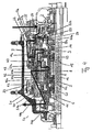
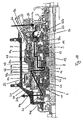
- Embodiments of the hub transmission with coaster brake according to the invention are illustrated in Figures 13 to 17 wherein the gear mechanism of the hub transmissions is substantially the same as in Figures 1 to 12 .
- the hub transmission according to Figures 1 to 12 is modified in Figures 13 to 17 insofar as clutches 53a, 54b are used that allow transmitting a reverse rotational force from driver 2 to the brake unit 80 which is coupled with the gear mechanism.
- the brake unit is explained with reference to Figures 13 and 15 .
- the same brake unit is also used in the embodiment according to Fig. 14 .
- the brake unit 80 is disposed distant from the driver 2 and is operatively connected with the driver 2 by means of the planetary gear mechanisms arranged therebetween.
- the brake unit 80 comprises a cup 81 which is non-rotatably connected with the hub shell 3 and, therefore, allows to transmit a rotational force to the hub shell 3.
- the cup 81 forms a circumferentially disposed braking surface 82 against which brake elements 83 can be pressed to transmit a reverse braking torque to the hub shell 3.
- Brake elements 83 comprise a plurality of circumferentially disposed arcuate brake shoes which are biased radially inwardly from the braking surface 82 by means of a brake spring 86. This arrangement is shown in Fig. 13 .
- Fig. 15 schematically shows the brake element 83 as one ring.
- the brake elements 82 are actuated by means of control elements 84 in the form of rollers which are disposed circumferentially on an axial end 31g of the planetary gear carrier 31 of the downstream planetary gear mechanism 6.
- the axial end 31g of the planetary gear carrier 31 comprises on its outer peripheral surface cam portions or cam surfaces 31f which cooperate with the plurality of rollers or control elements 84 to move same in a radially outward direction for actuating brake elements 83 if the planetary gear carrier 31 rotates in a reverse direction.
- the control elements 84 or the rollers, respectively, are held by a retaining element 85 which is designed as a roller cage supporting the plurality of circumferentially disposed rollers.
- the retaining element 85 is engaged with the planetary gear carrier 31 of the downstream planetary gear mechanism 6.
- the retaining element 85 comprises a radially extending projection 85a which is disposed between the brake unit 80 and the first planetary gear carrier 31 of the downstream planetary gear mechanism 6.
- a projection 85a of the retaining element 85 forms a circumferential support surface 85b.
- the first clutch 51 which couples the retaining element 85 and the cup 81.
- the clutch 51 comprises a plurality of circumferentially supposed pawls which are mounted to the retaining element 85 and the roller cage, respectively, and are biased radially outwardly by pawl springs for engaging an inner peripheral gear 81a formed on an inner side of cup 81.
- the pawls of the clutch 51 transmit a forward rotation of the first planetary gear carrier 31 to the cup 81 and hence to the hub shell 3.
- third and fourth one-way clutches 53, 54 are replaced in the embodiment according to Fig. 13 by third and fourth two-way clutches 53b, 54b.
- two-way clutches 53a, 54a are designed to transmit both a forward driving torque and a reverse braking torque.
- the design of the clutches 53a, 54a corresponds to the design disclosed in EP 1 413 509 B1 which is owned by the applicant.
- the fourth clutch 54a comprises a plurality of circumferentially disposed pawls 54b which engage with an inner peripheral gear portion of the second ring gear 22, in particular the clutch engaging portion 22b.
- Pawls 54b are biased radially outwardly by a pawl spring and thus function as a one-way clutch between the driver 2 and the second ring gear 22.
- a plurality of (braking) pawls 54c is circumferentially disposed for driving the second ring gear 22 in a rearward direction.
- the third clutch 53a is designed correspondingly to fourth clutch 54a.
- third clutch 53a As pawl control cage and ring spring of third clutch 53a disposed between third carrier 33 and first planetary gear carrier 31, the pawl control cage and the ring spring of third clutch 53a rotate in a reverse direction with the third carrier 33 within play.
- the pawl control cage of the third clutch 53a causes the driving pawls 53b to disengage and to engage the braking pawls 53c with the first planetary gear carrier 31. Accordingly, the first planetary gear carrier 31 rotates in a reverse direction.
- control elements 84 are outwardly forced by means of the cam surfaces 31f thereby applying a braking torque to the cup 81 and, hence, to the hub shell 3.
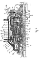
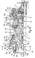
- the further embodiment according to Fig. 14 corresponds to the embodiment according to Fig. 13 except for the third clutch 53a which is replaced with an arrangement comprising a linking member 70 and a one way clutch 53.
- the function of the linking member 70 is to control the driving pawls of the third clutch 53, to control the braking pawls 53c between the linking member 70 and the third planetary gear carrier 33 and to transmit a braking rotation (reverse rotation) from the third planetary gear carrier 33 to the first planetary gear carrier 31.
- the linking member 70 controls to bring up or bring down the driving pawls and the braking pawls which are responsible for the forward or reverse rotation of the first planetary gear carrier 31.
- the linking member 70 has the form of a ring gear which meshes with the planetary gears 43 of the third planetary gear mechanism 8 without play and connects with the first planetary gear carrier 31 with play.
- the linking member 70 and the first planetary gear carrier 31 can rotate relative to each other within the predetermined play.
- EP 06 008 957 which is owned by the applicant.
- the hub transmission is in a driving stage
- the third planetary gear carrier 33 also rotates in a forward direction.
- the forward rotational force is transmitted from the third planetary gear carrier 33 to the first planetary gear carrier 31 via the driving pawls 53b of the third clutch 53.
- the first planetary gear carrier 31 rotates with the same speed as the linking member 70 in a forward direction.
- the forward rotational force is transmitted from the third planetary gear carrier 33 to the first planetary gear carrier 31 via the second or the third planetary gear mechanisms 7, 8 and the linking member 70.
- the first planetary gear carrier 31 rotates faster than the linking member 70 in a forward direction.
- the linking member 70 rotates relatively to the planetary gear carrier 31 within the play in the forward direction.
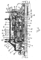
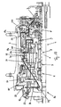
- the braking torque path in the embodiment according to Fig. 13 is indicated by the arrow in Fig. 16 and comprises the following elements:
- the braking path (reverse rotation path) of the embodiment according to Fig. 14 comprises the following elements:
Landscapes
- Engineering & Computer Science (AREA)
- Chemical & Material Sciences (AREA)
- Combustion & Propulsion (AREA)
- Transportation (AREA)
- Mechanical Engineering (AREA)
- Structure Of Transmissions (AREA)
Description
- The present invention relates to a hub transmission for a bicycle.
- Internally mounted multi-speed hub transmissions are mounted to the rear wheel of a bicycle and allow a rider of the bicycle to select different gear ratios to change the pedaling force. Typically a hub transmission comprises a hub axle that is mounted to the bicycle frame. The hub axle rotatably supports a driver for transmitting a pedaling force to the hub transmission through a sprocket and a chain. The hub transmission further comprises a hub shell which is likewise rotatably supported by the hub axle.
- The hub shell accommodates a power transmission mechanism which is disposed between the driver and the hub shell for transmitting rotational power from the driver to the hub shell. The power transmission mechanism provides a plurality of power transmission paths with different gear ratios that can be selected by means of a shift mechanism wherein each power transmission path typically produces a specific gear ratio. To establish the plurality of power transmission paths the power transmission mechanism ordinarily comprises several planetary gear mechanisms.
- Current internal hub transmissions are designed to provide 10 or more speed stages. The hub transmission according to
DE 10 2004 011 052 A1 allows a selection between 9 speed stages which are provided by a plurality of planetary gear mechanisms. The known hub transmission comprises three planetary gear mechanisms that allow to combine three speed stages with another five speed stages for a total of nine speed stages with a gear ration of 340%. The hub transmission includes a first planetary gear mechanism comprising a first sun gear that is non-rotatably mounted to the hub axle, a first planetary gear rotatably supported by a first planetary gear carrier and a first ring gear. The first planetary gears are disposed between the first sun gear and the first ring gear and meshing with the same. - A second planetary gear mechanism includes a second sun gear which is arranged on the first planetary gear carrier. Second planetary gears are mounted on the first ring gear.
- A third planetary gear mechanism is formed similar to the second planetary gear mechanism and includes a third sun gear mounted on the first planetary gear carrier. The third sun gear meshes with third planetary gears each of which are non-rotatably joined to the respective second planetary gears. Thereby a two-step planetary gear is formed. The third planetary gears mesh with a second ring gear to transmit the torque of the third planetary gear mechanism to the second planetary gear mechanism. The shifting mechanism of this hub transmission comprises a pawl carrier which allows coupling the driver selectively with components of the respective planetary gear mechanisms to produce different gear ratios. To this end the pawl carrier comprises a plurality of controllable pawls, namely six pawls that are actuated by means of three shifting cams.
- The arrangement of the two-step planetary gear on the first ring gear in combination with the second ring gear that meshes with the two-step planetary gears leads to a pile type of internal hub transmission. Since the second ring gear overlaps the other components of the three planetary gear mechanisms, the diameter of the second ring gear and, thus, the diameter of the internal hub transmission is increased. Moreover, the pile type construction of the internal hub transmission leads to an increased total weight of the hub.
- As described before, the second and third sun gears are each mounted on the first planetary gear carrier. Therefore, the second and third sun gears each rotate together with the first planetary gear carrier around the hub axle. In particular, the power transmission path for
speed stages speed stage 8, the third planetary gear rotates around the third sun gear and inspeed stage 9 the second planetary gear rotates around the second sun gear. - Due to this differential rotational type of the planetary gear mechanism the power transmission paths are complicated, in particular the power transmission paths for
speed stages - A similar hub transmission is known from
DE 197 20 796 A1 which discloses a multiple speed hub having a plurality of planetary gear mechanisms arranged in series. The hub transmission disclosed therein enables either a 7 speed shifting or a 14 speed shifting. The 14 speed hub transmission comprises five planetary gear mechanisms the components of which can be selectively locked to establish the desired power transmission paths. A first planetary gear mechanism comprises a first sun gear rotatably supported by a hub axle which can be locked with the same. The first sun gear meshes with the smaller diameter of a two-step planetary gear which is rotatably supported by a first planetary gear carrier. The first planetary gear carrier is non-rotatably connected with the hub shell. - The large diameter of the two-step planetary gear meshes with a ring gear that can be locked either with the hub axle or the first sun gear.
- A second planetary gear mechanism comprises a second sun gear rotatably supported by and lockable with the hub axle. Second planetary gears mesh with the sun gear and a second ring gear wherein the second ring gear is non-rotatably connected with the first sun gear.
- A third planetary gear mechanism comprises a third sun gear which is rotatably supported by and lockable with the hub axle. Third planetary gears mesh with the third sun gears which are non-rotatably connected with the second planetary gears with the respective second planetary gears. The second sun gear meshes with the small diameter stage of the stepped planetary gears, and the third sun gear meshes with the large diameter stage of the stepped planetary gears.
- The fourth and fifth planetary gear mechanisms are similar to the second and third planetary gear mechanisms and are symmetrically formed and arranged. The fourth and fifth planetary gear mechanisms therefore likewise comprise two-stage planetary gears wherein the planetary gears of the second and third planetary gear mechanism and the planetary gears of the fourth and fifth planetary gear mechanisms are rotatably supported by means of a common planetary gear carrier. The small diameter stage of the stepped planetary gears of the fourth and fifth planetary gear mechanisms mesh with a ring gear that is non-rotatably connected with a driver.
- A further embodiment of the 14-speed hub transmission is based on a modified embodiment of the afore described hub transmission and comprises a second ring gear which meshes with both small diameter stages of the symmetrically arranged stepped planetary gears. The common planetary gear carrier is replaced with two separate plantetary gear carriers wherein the planetary gear carrier of the second and third planetary gear mechanisms is non-rotatably connected with the first sun gear. The planetary gear carrier of the fourth and fifth planetary gear mechanisms is non-rotatably connected with the driver.
- Due to the increased number of clutches required for locking the separate components of the planetary gear mechanisms, for example the ring gears with the sun gears, the hub transmission according to
DE 197 20 796 A1 is complicated and comparatively expensive. - Document
DE 197 45 419 discloses another bicycle transmission, comprising: - a hub axle;
- a driver rotatably supported by the hub axle;
- a hub shell rotatably supported by the hub axle;
- a power transmission mechanism disposed between the driver and the hub shell for transmitting rotational power from the driver to the hub shell through a plurality of power transmission paths; and
- a shift mechanism for selecting one of the plurality of power transmission paths;
- It is an object of the invention to provide a hub transmission for a bicycle comprising a plurality of speed stages and enabling a lightweight and compact construction.
- According to the invention, this object is accomplished by a hub transmission for a bicycle comprising the features of
claim 1. - The invention is based on the idea to provide a hub transmission for a bicycle that comprises a hub axle, a driver and a hub shell each of which are rotatably supported by the hub axle. The hub transmission further comprises a power transmission mechanism that is disposed between the driver and the hub shell for transmitting rotational power from the driver to the hub shell through a plurality of power transmission paths and a shift mechanism for selecting one of the plurality of power transmission paths. The power transmission mechanism comprises a plurality of planetary gear mechanisms wherein a planetary gear carrier of a downstream planetary gear mechanism meshes with planetary gears of an upstream planetary gear mechanism or with a linking member which is coupled with the planetary gears of the upstream planetary gear mechanism.
- The planetary gear carrier of the downstream planetary gear mechanism is coupled with a brake unit for transmitting a reverse rotational power from the driver to the brake unit.
- The downstream planetary gear mechanism comprises at least a first planetary gear mechanism, and the upstream planetary gear mechanism comprises at least second, third and fourth planetary gear mechanisms.
- A hub transmission structure with an integrated brake unit is known, for example, from
EP 1849699 which is owned by the applicant. However, the known hub transmissions lack the specific coupling of the downstream planetary gear carrier with the upstream planetary gear carrier or with the linking member wherein the brake unit is coupled with the downstream planetary gear carrier. - A hub transmission formed in accordance with the invention has a plurality of advantages. Since the planetary gear carrier of the downstream planetary gear mechanism meshes with planetary gears of the upstream planetary gear mechanism, a compact design is achieved that allows providing a plurality of power transmission paths while maintaining a small diameter of the hub. The aforementioned coupling of the downstream planetary gear carrier with upstream planetary gears further allows realizing the plurality of power transmission paths by means of a comparatively simple structure that reduces the risk of a failure of components of the transmission. Due to the surprisingly simple structure of the inventive hub transmission it is possible to produce a hub transmission that enables a comparatively great number of gear ratios at relatively low costs. The invention has the further advantage that the planetary gear carrier of the downstream planetary gear mechanism can be coupled with a brake unit to provide a hub transmission with an integrated brake.
- In a preferred embodiment the power transmission mechanism comprises at least four planetary gear mechanisms that are arranged in series. Thereby it is possible to realize a 11-speed hub transmission with a compact design and a relatively small hub diameter.
- The first planetary gear mechanism may comprise the planetary gear carrier of the downstream planetary gear mechanism. The third gear mechanism may comprise the planetary gears of the upstream planetary gear mechanism. This means that the first and third planetary gear mechanisms are coupled by means of the downstream or first planetary gear mechanism which meshes with the upstream or third planetary gears.
- Preferably the planetary gear carrier of the downstream planetary gear mechanism comprises a carrier portion and a ring gear portion which meshes with the planetary gears of the upstream planetary gear mechanism or with the linking member which is coupled with the planetary gears of the upstream planetary gear mechanism, wherein the carrier portion and the ring gear portion are non-rotatably connected, in particular integrally formed. Hence. it is to be emphasised that the planetary gear carrier of the downstream planetary gear mechanism fulfils two functions, namely a support function for the planetary gears of the first planetary gear mechanism and a power transmission function for the planetary gears of the upstream planetary gear mechanism.
- Due to the non-rotatable connection between the carrier portion and the ring gear portion the compact design of the hub transmission is optimized. Moreover, it is possible to directly mesh the ring gear portion with the planetary gears of the upstream planetary gear mechanism or alternatively to provide, as an intermediate component between the upstream planetary gear mechanism and the ring gear portion a linking member which is coupled with the planetary gears of the upstream planetary gear mechanism. Thereby, it is possible to use different braking clutch means with the aforementioned embodiments.
- Preferably the planetary gear carrier of the downstream planetary gear mechanism is connectable with the fourth planetary gear mechanism. Thereby, a number of further power transmission paths can be realized.
- The connection of the planetary gear carrier and the downstream planetary gear mechanism with the fourth planetary gear mechanism can be realized, for example, by means of a preferred embodiment wherein the planetary gear carrier of the downstream planetary gear mechanism comprises a clutch engaging portion which is connectable with a planetary gear carrier of the fourth planetary gear mechanism.
- To enable a transmission of a rotational force from the planetary gear carrier of the downstream planetary gear mechanism to the hub shell, the planetary gear carrier of the downstream planetary gear mechanism is connectable with the hub shell by means of a first clutch.
- The first planetary gear mechanism further comprises a first sun gear rotatably supported by and lockable with the hub axle, a first ring gear coaxially arranged with the first sun gear and a plurality of first planetary gears meshing with the first sun gear and the first ring gear, wherein the first planetary gears are rotatably supported by the planetary gear carrier of the first planetary gear mechanism. The first planetary gear mechanism corresponds to the downstream planetary gear mechanism.
- The first ring gear is connectable with the hub shell by a second clutch for transmitting a rotational force from the first ring gear to the hub shell.
- The second planetary gear mechanism comprises a second sun gear rotatably supported by and lockable with the hub axle. Preferably the second planetary gear mechanism also comprises a second planetary gear carrier rotatably supported relative to the hub axle and a plurality of second planetary gears rotatably supported by the second planetary gear carrier and meshing with the second sun gear.
- The third planetary gear mechanism comprises a third sun gear rotatably supported by and lockable with the hub axle. Preferably the planetary gears of the third planetary gear mechanism are rotatably supported by the second planetary gear carrier and mesh with the third sun gear.
- The planetary gears of the third planetary gear mechanism and the second planetary gears of the second planetary gear mechanism may be non-rotatably connected, in particular integrally formed to form stepped planetary gears respectively.
- In a further preferred embodiment the fourth planetary gear mechanism comprises a fourth sun gear non-rotatably fixed to the hub axle, a second ring gear co-axially arranged with the fourth sun gear and a plurality of fourth planetary gears rotatably supported by a third planetary gear carrier wherein the fourth planetary gears mesh with the fourth sun gear and the second ring gear.
- The third planetary gear carrier can engage with the second planetary gear carrier.
- A third clutch may be disposed between the third planetary gear carrier and the first planetary gear carrier, in particular the clutch engaging portion for transmitting a rotational force from the third planetary gear carrier to the first planetary gear carrier. A fourth clutch can be disposed between the driver and the second ring gear for transmitting a rotational force from the driver to the second ring gear. A fifth clutch may be disposed between the driver and the third planetary gear carrier for transmitting a rotational force from the driver to the third planetary gear carrier.
- In a further preferred embodiment, the brake unit comprises a cup which is non-rotatably connected with the hub shell and forms a circumferentially disposed braking surface.
- The brake unit comprises brake elements which are adapted to cooperate with the braking surface for applying a braking torque and control elements for actuating the brake elements. The control elements are coupled with the planetary gear carrier of the downstream planetary gear mechanism such that an actuation of the brake elements is effected by a reverse rotation of the planetary gear carrier of the downstream planetary gear mechanism. This embodiment provides a reliable and compact brake unit which is coupled with the planetary gear carrier of the downstream planetary gear mechanism to actuate the brake unit. As the planetary gear carrier of the downstream planetary gear mechanism operatively connects the brake unit with the upstream planetary gear mechanism an optimal transmission of the reverse rotational force from the driver to the brake unit is accomplished.
- The first clutch can be disposed between the cup and the planetary gear carrier of the downstream planetary gear mechanism. Thereby it is possible to transmit a forward rotational force from the planetary gear carrier of the downstream planetary gear to the hub shell via the cup which is non-rotatably connected with the hub shell. This arrangement allows to reduce the length of the hub transmission and improves the compact design thereof.
- The first clutch can be supported by a retaining element for the control elements. This embodiment further minimizes the space used for the brake unit.
- In a further embodiment, the control elements comprise a plurality of rollers which cooperate with a plurality of cam surfaces provided on the planetary gear carrier on the downstream planetary gear. The retaining element comprises a roller cage supporting the rollers wherein the roller cage is engaged with the planetary gear carrier of the downstream planetary gear mechanism. The engagement of the roller cage with the planetary gear carrier of the downstream planetary gear mechanism enables a simple and efficient actuation of the brake units if the planetary gear carrier is rotated in a reverse direction and, thus, also the roller cage. Thereby, the rollers contained in the roller cage cooperate with the cam surfaces such that the rollers push the brake elements against the braking surface for applying a braking torque.
- Preferably, the fourth clutch can be disposed between the driver and the second ring gear and comprises driving pawls and braking pawls which are adapted to be selectively activated by a forward or reverse rotation of the driver to rotate the second ring gear in a forward or reverse direction.
- The invention will now be described by way of example with reference to the accompanying drawings in which:
- Fig. 1
- is a longitudinal cross-sectional view of a hub transmission without brake unit to describe the principles of the design in the gear mechanisms of a hub transmission suitable for the invention;
- Fig. 2
- is a longitudinal cross-sectional view of the hub transmission according to
Fig. 1 inspeed stage 1; - Fig. 3
- is a longitudinal cross-sectional view of the hub transmission according to
Fig. 1 inspeed stage 2; - Fig. 4
- is a longitudinal cross-sectional view of the hub transmission according to
Fig. 1 inspeed stage 3; - Fig. 5
- is a longitudinal cross-sectional view of the hub transmission according to
Fig. 1 inspeed stage 4; - Fig. 6
- is a longitudinal cross-sectional view of the hub transmission according to
Fig. 1 inspeed stage 5; - Fig. 7
- is a longitudinal cross-sectional view of the hub transmission according to
Fig. 1 inspeed stage 6; - Fig. 8
- is a longitudinal cross-sectional view of the hub transmission according to
Fig. 1 inspeed stage 7; - Fig. 9
- is a longitudinal cross-sectional view of the hub transmission according to
Fig. 1 inspeed stage 8; - Fig. 10
- is a longitudinal cross-sectional view of the hub transmission according to
Fig. 1 inspeed stage 9; - Fig. 11
- is a longitudinal cross-sectional view of the hub transmission according to
Fig. 1 in speed stage 10; and - Fig. 12
- is a longitudinal cross-sectional view of the hub transmission according to
Fig. 1 inspeed stage 11; - Fig. 13
- is a longitudinal cross sectional view of a hub transmission according to an embodiment of the invention with a brake unit;
- Fig. 14
- is a longitudinal cross sectional view of a hub transmission according to a further embodiment of the invention;
- Fig. 15
- is a cross sectional view of the brake unit along the line A-A in
Fig. 13 ; - Fig. 16
- is a view of the hub transmission according to
Fig. 13 wherein the braking torque path through the hub transmission is illustrated; and - Fig. 17
- is a view of the hub transmission according to
Fig. 14 wherein the braking torque path through the hub transmission is illustrated. -
Figures 1 to 12 refer to a hub transmission without brake unit to explain the design and function of the gear mechanisms provided in the hub transmission. The hub transmission according toFigures 1 and12 is supplemented inFigures 13 to 17 by a brake unit which is coupled with the most downstream planetary gear mechanism to produce a braking force if the planetary gear mechanism is rotated in a reverse direction. The planetary gear mechanisms shown inFigures 1 to 12 and explained in the following in detail correspond to the planetary gear mechanisms of the hub transmissions according toFigures 13 to 17 . -
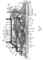
Fig. 1 illustrates a hub transmission that can be mounted to the rear wheel of a bicycle. The hub transmission comprises ahub axle 1 and adriver 2 which is rotatably supported by thehub axle 1. The hub transmission further comprises ahub shell 3 which is rotatably supported byhub axle 1. Apower transmission mechanism 4 is disposed between thedriver 2 and thehub shell 3 for transmitting rotational power fromdriver 2 to thehub shell 3 through a plurality of power transmission paths that can be selected to change the gear ratio as desired by the rider. To select one of the plurality of power transmission paths, ashift mechanism 5 is provided. - The
shift mechanism 5 corresponds to the shift mechanism which is described in detail inEP 1 323 627 A2US 6,607,465 B1 mentioned therein. - The
power transmission mechanism 4 comprises a plurality ofplanetary gear mechanisms driver 2 than the downstream planetary gear mechanism. As seen in the direction of the rotational power flow, the downstream planetary gear mechanism is arranged after the upstream planetary gear mechanism. For example, the downstream planetary gear mechanism comprises the firstplanetary gear mechanism 6 and the upstream planetary gear mechanism comprises the thirdplanetary gear mechanism 8. - The plurality of
planetary gear mechanisms planetary gear mechanisms - As is evident from
Fig. 1 , the downstream planetary gear mechanism comprises aplanetary gear carrier 31, and the upstream planetary gear mechanism comprisesplanetary gears 43 wherein theplanetary gear carrier 31 of the downstream or firstplanetary gear mechanism 6 meshes withplanetary gears 43 of the upstream or thirdplanetary gear mechanism 8. - In general, the
planetary gear carrier 31 has a longitudinally extending shape that is adapted to overlap components ofpower transmission mechanism 4 that are arranged upstream of the firstplanetary gear mechanism 6 and, thus, more proximate to thedriver 2 than the downstreamplanetary gear mechanism 6. - In particular, the
planetary gear carrier 31 of the downstreamplanetary gear mechanism 6 axially extends from the area of the downstream or firstplanetary gear mechanism 6 to the area of the upstream or thirdplanetary gear mechanism 8. As illustrated inFig. 1 , theplanetary gear carrier 31 axially extends over more than 1/3 to 1/2 of the entire length of the hub transmission. The axial extension of theplanetary gear carrier 31 is such that the secondplanetary gear mechanism 7 which is arranged between the downstreamplanetary gear mechanism 6 and the upstreamplanetary gear mechanism 8 is overlapped by theplanetary gear carrier 31. In the embodiment according toFig. 1 , the secondplanetary gear mechanism 7 is not engaged with theplanetary gear carrier 31. - The
planetary gear carrier 31 comprises a stepped shape wherein the inner diameter of the subsequent steps increases towards thedriver 2. The stepped shape of theplanetary gear carrier 31 will be described in more detail in conjunction with the respective components associated thereto. - The
planetary gear carrier 31 further comprises a clutch engaging portion 31 c which is arranged on the axial end of theplanetary gear carrier 31 proximate to thedriver 2. The clutch engaging portion 31c is provided to engage with/disengage from a clutch 53 (third clutch) which will be described in more detail in connection with the fourthplanetary gear mechanism 9. - The
planetary gear carrier 31 further comprises aring gear portion 31b. Thering gear portion 31b is integrally connected with the clutch engaging portion 31c and is formed with a smaller inner diameter than clutch engaging portion 31c. Thering gear portion 31b meshes withplanetary gears 43 of the upstream or thirdplanetary gear mechanism 8. The inner diameter of thering gear portion 31b is larger than the outer diameter of secondplanetary gears 42 of the secondplanetary gear mechanism 7 to avoid engagement or collision therewith. - The
ring gear portion 31b is integrally connected with a carrier portion 31a which supports firstplanetary gears 41 of the first downstreamplanetary gear mechanism 6. The firstplanetary gears 41 are rotatably supported by first planetary gear shafts 41a which are disposed in a carrier portion 31a of theplanetary gear carrier 31. Typically, three ore more firstplanetary gears 41 are provided in the firstplanetary gear mechanism 6. - A further
clutch engaging portion 31d is integrally formed with the carrier portion 31a and is provided for engaging with/disengaging from a first clutch 51 to establish/interrupt a power transmission from theplanetary gear carrier 31 to thehub shell 3. A further or secondclutch engaging portion 31d is arranged downstream of theplanetary gear mechanism 6. Thering gear portion 31b and the (first) clutch engaging portion 31c are located upstream of theplanetary gear mechanism 6. Again, the downstream or upstream arrangement of components is seen and to be understood in the direction of the power flow. - The plurality of
planetary gear mechanisms - The first
planetary gear mechanism 6 is arranged most downstream or most distant from thedriver 2 and comprises afirst sun gear 11 which is rotatably supported by and lockable with thehub axle 1. Between an inner peripheral surface of thefirst sun gear 11 and thehub axle 1, a first sungear guide ring 61 is non-rotatably fixed to thehub axle 1. A first sungear guide ring 61 allows to lock and unlock thefirst sun gear 11 by means of theshifting mechanism 5. Coaxially arranged in relation to and rotatably supported by thehub axle 1 is afirst ring gear 21 wherein the aforementioned plurality of firstplanetary gears 41 are rotatably supported by the (first)planetary gear carrier 31 and mesh with thefirst sun gear 11 and thefirst ring gear 21. - As illustrated in
Fig. 1 , the firstplanetary gears 41 comprise two gear stages wherein the large diameter gear stage meshes with thefirst sun gear 11 and the small diameter gear stage meshes with thering gear 21. Small diameter gear stage of firstplanetary gears 41 is arranged proximate to the secondplanetary gear mechanism 7. Thering gear 21 can be connected with or disconnected from thehub shell 3 by means of a second (one-way) clutch 52 which is disposed between thefirst ring gear 21 and thehub shell 3. - As described above, the
ring gear carrier 31 of the firstplanetary gear mechanism 6 extends axially beyond theplanetary gears 41 in a longitudinal direction of the hub transmission thereby overlapping at least the subsequently arranged upstream second and thirdplanetary gear mechanisms planetary gear carrier 31 is adapted to partially accommodate thering gear 21 and forms ashoulder 31e such that thering gear 21 is arranged between theshoulder 31e and the large diameter gear stage of the first planetary gears 41. - The second
planetary gear mechanism 7 is located upstream of the firstplanetary gear mechanism 6 and comprises asecond sun gear 12 which is rotatably supported by and lockable with thehub axle 1. Between an inner surface of thesecond sun gear 12 and thehub axle 1, a second sungear guide ring 62 is non-rotatably fixed to thehub axle 1. A plurality of secondplanetary gears 42 is rotatably supported by a secondplanetary gear carrier 32 which is rotatably supported by thehub axle 1. To this end, the secondplanetary gears 42 are rotatably supported by a secondplanetary gear shaft 42a which is supported by a secondplanetary gear carrier 32. Typically three or more secondplanetary gears 42 are provided. - The third
planetary gear mechanism 8 is arranged upstream of the secondplanetary gear mechanism 7 and comprises athird sun gear 13 which is rotatably supported by and lockable with thehub axle 1. Between an inner peripheral surface of athird sun gear 13 and thehub axle 1, a third sungear guide ring 63 is arranged and non-rotatably fixed tohub axle 1. The third sungear guide ring 63 can be actuated by means of theshifting mechanism 5 to lock/unlock thesun gear 13. A plurality of thirdplanetary gears 43 meshes with thethird sun gear 13 and is rotatably supported by the secondplanetary gear carrier 32. In particular, thirdplanetary gears 43 are arranged on second aplanetary gear shaft 42a which, thus, represents a common planetary gear shaft for the second and thirdplanetary gears - As is evident from
Fig. 1 , second and third planetary gears are non-rotatably connected and integrally form a stepped planetary gear 402. The small diameter gear stage of the stepped planetary gear 402 meshes with thesecond sun gear 12, and the large diameter gear stage of the stepped planetary gear 402 meshes with thethird sun gear 8. Moreover, the large diameter gear stage of the stepped planetary gear 402 meshes with thering gear portion 31b of the downstreamplanetary gear carrier 31. Thus, it is possible to establish a transmission path connecting thethird sun gear 8 with the firstplanetary gear carrier 31. - A fourth
planetary gear mechanism 9 is arranged upstream of the thirdplanetary gear mechanism 8 and represents the planetary gear mechanism closest to thedriver 2. The fourthplanetary gear mechanism 9 comprises afourth sun gear 14 which is non-rotatably fixed to thehub axle 1. Asecond ring gear 22 is coaxially arranged with and rotatably supported by thehub axle 1. Between thesecond ring gear 22 and the fourth sun gear 14 a plurality of fourthplanetary gears 44 is arranged which are formed as two-step planetary gears. The large diameter gear stage of theplanetary gears 44 meshes with thering gear 22 and the small diameter gear stage of the fourthplanetary gears 44 meshes with thefourth sun gear 14. Typically three or more fourthplanetary gears 44 are provided. - The fourth
planetary gears 44 are rotatably supported by a thirdplanetary gear carrier 33 which can rotate around thehub axle 1. The thirdplanetary gear carrier 33 comprises third planetary gear shafts 44a which rotatably support the fourth planetary gears 44. The thirdplanetary gear carrier 33 is engaged with the secondplanetary gear carrier 32 to transmit power from the thirdplanetary gear carrier 33 to the secondplanetary gear carrier 32. - As is readily apparent from
Fig. 1 , the middle axes of the secondplanetary gear shafts 42a and the third planetary gear shafts 44a are radially spaced apart. The middle axes of third planetary gear shafts 44a are arranged on a cylindrical plane having a larger diameter than a cylindrical plane which comprises the middle axes of the secondplanetary gear shafts 42a. The cylindrical plane which comprises the middle axes of first planetary gear shafts 41a corresponds to the cylindrical plane of the middle axes of third planetary gear shafts 44a. Thus, the middle axes of the secondplanetary gear shafts 42a which are arranged between the first and fourthplanetary gear mechanisms hub axle 1 than the middle axes of the first and third planetary gear shafts 41a, 44a, respectively. - The third
planetary gear carrier 33 of the fourthplanetary gear mechanism 9 can be connected to the downstreamplanetary gear carrier 31. For this purpose, the third clutch 53 mentioned above is provided between the thirdplanetary gear carrier 33 and the firstplanetary gear carrier 31. In particular, the third clutch 53 is arranged at an end of the thirdplanetary gear carrier 33 distant from thedriver 2 and engages with/disengages from the clutch engaging portion 31c of downstream of the firstplanetary gear carrier 31. For the power transmission from thedriver 2 to the fourthplanetary gear mechanism 9, fourth andfifth clutches 54and 55 are provided. - The fourth clutch 54 is a one-way clutch disposed between the
driver 2 and thesecond ring gear 22. Thesecond ring gear 22 comprises anaxial projection 22a which extends towards thedriver 2. Theaxial projection 22a comprises on its inner peripheral surface aclutch engaging portion 22b which cooperates with the fourth clutch 54 to lock or unlock thesecond ring gear 22 with thedriver 2. The fourth clutch 54 is supported by an axial projection 2a of thedriver 2 that extends in parallel with theaxial projection 22a of thering gear 22. - For
speed stages 1 to 6, the fourth clutch 54 is engaged with thering gear 22 to transmit power from thedriver 2 to thering gear 22. - For
speed stages 7 to 11, a fifth clutch 55 is provided which is disposed between thedriver 2 and the thirdplanetary gear carrier 33 for transmitting rotational power from thedriver 2 to the thirdplanetary gear driver 33. The fifth clutch 55 is formed as a clutch ring and is axially movable in a longitudinal direction of thehub axle 1. The fifth clutch 55 comprises twoengaging portions driver 2 and the thirdplanetary gear carrier 33, respectively. - The clutch
engaging portion 2b of thedriver 2 is formed on the inner peripheral surface of the axial projection 2a and engages with the upper orradial engaging portion 55b of thefifth clutch 55. The clutch engaging portion 33a of the thirdplanetary gear carrier 33 is adapted to engage with/disengage from the lower or axialengaging portion 55a of thefifth clutch 55. - For
speed stages 7 to 11, the axial engagingportion 55a of the fifth clutch 55 and the clutch engaging portion 33a of the thirdplanetary gear carrier 33 are coupled and the fourth clutch 54 is uncoupled. - A more detailed description of the aforementioned clutch mechanism including the fourth and
fifth clutches EP 1 323 627 A2EP 1 947 003 - The function of the hub transmission according to
Fig. 1 is explained with reference toFigures 2 to 12 in which the coupling of the various components for each speed stage and the specific power transmission path realized thereby are illustrated. The bold lines and arrows indicated inFigures 2 to 12 illustrate the rotational power flow through thepower transmission mechanism 4. The coupling of the various components as well as the power transmission paths are indicated in the following Tables 1 and 2 wherein Table 1 concerns the coupling of the components and Table 2 concerns the specific power transmission path.Table 1 Speed Stage Clutch ring 55 (Driver and 3rd Planetary gear carrier 33) First Sun gear 11 Second Sun gear 12 Third Sun gear 13 Gear ratio 1 Disengaged Free Free Free 0.527 2 Disengaged Locked Free Free 0.681 3 Disengaged Free Free Locked 0.770 4 Disengaged Free Locked Free 0.873 5 Disengaged Locked Free Locked 0.995 6 Disengaged Locked Locked Free 1.127 7 Engaged Locked Free Free 1.292 8 Engaged Free Free Locked 1.462 9 Engaged Free Locked Free 1.656 10 Engaged Locked Free Locked 1.888 11 Engaged Locked Locked Free 2.139 Table 2 Speed Stage Power Transmission Path 1 Driver - 4th clutch 54 - 2nd ring gear 22 - (4th planet gear 44 rotates around 4th sun gear 14) - 3rd planetary gear carrier 33 - 3rd clutch 53 - 1st planetary carrier 31 - 1st clutch 51 - Hub Shell 2 Driver - 4th clutch 54 - 2nd ring gear 22 - (4th planet gear 44 rotates around 4th sun gear 14) - 3rd planetary gear carrier 33 - 3rd clutch 53 - 1st planetary carrier 31 - (1st planet gear 41 rotates around 1st sun gear 11) - 1st ring gear 21 - 2nd clutch 52 - Hub Shell 3 Driver - 4th clutch 54 - 2nd ring gear 22 - (4th planet gear 44 rotates around 4th sun gear 14) - 3rd planetary gear carrier 33 - 2nd planetary gear carrier 32 - (3rd planet gear 43 rotates around 3rd sun gear 13) - 1st planetary gear carrier 31 - 1st clutch 51 - Hub Shell 4 Driver - 4th clutch 54 - 2nd ring gear 22 - (4th planet gear 44 rotates around 4th sun gear 14) - 3rd planetary gear carrier 33 - 2nd planetary gear carrier 32 - (2nd planet gear 42 rotates around 2nd sun gear 12) - 1st planetary gear carrier 31 - 1st clutch 51 - Hub Shell 5 Driver - 4th clutch 54 - 2nd ring gear 22 - (4th planet gear 44 rotates around 4th sun gear 14) - 3rd planetary gear carrier 33 - 2nd planetary gear carrier 32 - (3rd planet gear 43 rotates around 3rd sun gear 13) - 1st planetary carrier 31 - (1st planet gear 41 rotates around 1st sun gear 11) - 1st ring gear 21 - 2nd clutch 52 - Hub Shell 6 Driver - 4th clutch 54 - 2nd ring gear 22 - (4th planet gear 44 rotates around 4th sun gear 14) - 3rd planetary gear carrier 33 - 2nd planetary gear carrier 32 - (2nd planet gear 42 rotates around 2nd sun gear 12) - 1st planetary carrier 31 - (1st planet gear 41 rotates around 1st sun gear 11) - 1st ring gear 21 - 2nd clutch 52 - Hub Shell 7 Driver - 5th clutch 55 - 3rd planetary gear carrier 33 - 3rd clutch 53 - 1st planetary carrier 31 - (1st planet gear 41 rotates around 1st sun gear 11) - 1 st ring gear 21 - 2nd clutch 52 - Hub Shell 8 Driver - 5th clutch 55 - 3rd planetary gear carrier 33 - 2nd planetary gear carrier 32 - (3rd planet gear 43 rotates around 3rd sun gear 13) - 1st planetary gear carrier 31 - 1st clutch 51 - Hub Shell 9 Driver - 5th clutch 55 - 3rd planetary gear carrier 33 - 2nd planetary gear carrier 32 - (2nd planet gear 42 rotates around 2nd sun gear 12) - 1st planetary gear carrier 31 - 1st clutch 51 - Hub Shell 10 Driver - 5th clutch 55 - 3rd planetary gear carrier 33 - 2nd planetary gear carrier 32 - (3rd planet gear 43 rotates around 3rd sun gear 13) - 1st planetary carrier 31 - (1st planet gear 41 rotates around 1st sun gear 11) - 1 st ring gear 21 - 2nd clutch 52 - Hub Shell 11 Driver - 5th clutch 55 - 3rd planetary gear carrier 33 - 2nd planetary gear carrier 32 - (2nd planet gear 42 rotates around 2nd sun gear 12) - 1st planetary carrier 31 - (1st planet gear 41 rotates around 1st sun gear 11) - 1st ring gear 21 - 2nd clutch 52 - Hub Shell - In summary, the hub transmission according to the described embodiment of the invention allows the realization of an 11 speed internal hub transmission wherein the diameter of the
hub shell 2 is similar to the diameter of a currently available 8 speed hub transmission. This means that the hub transmission of the invention provides more speed stages than the conventional hub transmission without increasing the hub diameter. Moreover, the hub transmission according toFig. 1 provides the advantage that all transmission paths are simple which leads to a efficient power transmission. - In general, the
planetary gear carrier 31 of the downstreamplanetary gear mechanism 6 has an axially elongated shape adapted to mesh with theplanetary gears 43 of the upstreamplanetary gear mechanism 8. Moreover, the axially elongated shape of theplanetary gear carrier 31 allows for coupling/uncoupling theplanetary gear carrier 31 with/from aplanetary gear carrier 33 of a further upstreamplanetary gear mechanism 9. In particular, the axially elongatedplanetary gear carrier 31 of the downstreamplanetary gear mechanism 6 is adapted to selectively transmit rotational power from theplanetary gears 43 of an upstreamplanetary gear mechanism 8 and to selectively transmit rotational power from theplanetary gear carrier 33 of the further upstreamplanetary gear mechanism 9. - The axially elongated shape of the downstream
planetary gear carrier 31 allows for a compact, small diameter internal hub transmission for a bicycle with highly efficient transmission paths. - Embodiments of the hub transmission with coaster brake according to the invention are illustrated in
Figures 13 to 17 wherein the gear mechanism of the hub transmissions is substantially the same as inFigures 1 to 12 . The hub transmission according toFigures 1 to 12 is modified inFigures 13 to 17 insofar asclutches 53a, 54b are used that allow transmitting a reverse rotational force fromdriver 2 to thebrake unit 80 which is coupled with the gear mechanism. The brake unit is explained with reference toFigures 13 and15 . The same brake unit is also used in the embodiment according toFig. 14 . - The
brake unit 80 is disposed distant from thedriver 2 and is operatively connected with thedriver 2 by means of the planetary gear mechanisms arranged therebetween. Thebrake unit 80 comprises acup 81 which is non-rotatably connected with thehub shell 3 and, therefore, allows to transmit a rotational force to thehub shell 3. Thecup 81 forms a circumferentially disposedbraking surface 82 against whichbrake elements 83 can be pressed to transmit a reverse braking torque to thehub shell 3. -
Brake elements 83 comprise a plurality of circumferentially disposed arcuate brake shoes which are biased radially inwardly from thebraking surface 82 by means of abrake spring 86. This arrangement is shown inFig. 13 .Fig. 15 schematically shows thebrake element 83 as one ring. Thebrake elements 82 are actuated by means ofcontrol elements 84 in the form of rollers which are disposed circumferentially on anaxial end 31g of theplanetary gear carrier 31 of the downstreamplanetary gear mechanism 6. Theaxial end 31g of theplanetary gear carrier 31 comprises on its outer peripheral surface cam portions orcam surfaces 31f which cooperate with the plurality of rollers or controlelements 84 to move same in a radially outward direction for actuatingbrake elements 83 if theplanetary gear carrier 31 rotates in a reverse direction. - The
control elements 84 or the rollers, respectively, are held by a retainingelement 85 which is designed as a roller cage supporting the plurality of circumferentially disposed rollers. The retainingelement 85 is engaged with theplanetary gear carrier 31 of the downstreamplanetary gear mechanism 6. The retainingelement 85 comprises aradially extending projection 85a which is disposed between thebrake unit 80 and the firstplanetary gear carrier 31 of the downstreamplanetary gear mechanism 6. Aprojection 85a of the retainingelement 85 forms a circumferential support surface 85b. - On the support surface 85b, the first clutch 51 is provided which couples the retaining
element 85 and thecup 81. The clutch 51 comprises a plurality of circumferentially supposed pawls which are mounted to the retainingelement 85 and the roller cage, respectively, and are biased radially outwardly by pawl springs for engaging an inner peripheral gear 81a formed on an inner side ofcup 81. The pawls of the clutch 51 transmit a forward rotation of the firstplanetary gear carrier 31 to thecup 81 and hence to thehub shell 3. - To effect the reverse rotation of the
planetary gear mechanisms hub shell 3, third and fourth one-way clutches Figures 1 to 12 are replaced in the embodiment according toFig. 13 by third and fourth two-way clutches 53b, 54b. Also, two-way clutches clutches EP 1 413 509 B1second ring gear 22, in particular the clutch engagingportion 22b. Pawls 54b are biased radially outwardly by a pawl spring and thus function as a one-way clutch between thedriver 2 and thesecond ring gear 22. A plurality of (braking)pawls 54c is circumferentially disposed for driving thesecond ring gear 22 in a rearward direction. The third clutch 53a is designed correspondingly to fourth clutch 54a. - The embodiment according to
Fig. 13 functions as follows: - The
driver 2 rotates relative to thesecond ring gear 22 with small angles as play. Thepawls 54b, 54c are supported by a pawl control cage and a ring spring disposed between thedriver 2 and thesecond ring gear 22. When thedriver 2 rotates in a reverse direction, a relative rotation between thedriver 2 and thesecond ring gear 22 occurs at small angles and, at the same time, the ring spring rotates with thedriver 2 in a reverse direction. The reverse rotation of the ring spring causes a reverse rotation of pawl control cage which, in turn, provides for bringing down the driving pawls 54b and bringing up thebraking pawls 54c. Since thebraking pawls 54c engage with the inner teeth of theclutch engaging portion 22b of thesecond ring gear 22, a reverse rotational force of thedriver 2 is transmitted to thesecond ring gear 22 via thebraking pawls 54c. Accordingly thesecond ring gear 22 rotates in a reverse direction. - As
fourth sun gear 14 meshes with the fourthplanetary gear 44, the reverse rotational force of thesecond ring gear 22 is transmitted to thirdplanetary gear carrier 33. - As pawl control cage and ring spring of third clutch 53a disposed between
third carrier 33 and firstplanetary gear carrier 31, the pawl control cage and the ring spring of third clutch 53a rotate in a reverse direction with thethird carrier 33 within play. The pawl control cage of the third clutch 53a causes the driving pawls 53b to disengage and to engage thebraking pawls 53c with the firstplanetary gear carrier 31. Accordingly, the firstplanetary gear carrier 31 rotates in a reverse direction. - Thus, the
control elements 84 are outwardly forced by means of thecam surfaces 31f thereby applying a braking torque to thecup 81 and, hence, to thehub shell 3. - The further embodiment according to
Fig. 14 corresponds to the embodiment according toFig. 13 except for the third clutch 53a which is replaced with an arrangement comprising a linkingmember 70 and a oneway clutch 53. - The function of the linking
member 70 is to control the driving pawls of the third clutch 53, to control thebraking pawls 53c between the linkingmember 70 and the thirdplanetary gear carrier 33 and to transmit a braking rotation (reverse rotation) from the thirdplanetary gear carrier 33 to the firstplanetary gear carrier 31. Thus, the linkingmember 70 controls to bring up or bring down the driving pawls and the braking pawls which are responsible for the forward or reverse rotation of the firstplanetary gear carrier 31. The linkingmember 70 has the form of a ring gear which meshes with theplanetary gears 43 of the thirdplanetary gear mechanism 8 without play and connects with the firstplanetary gear carrier 31 with play. Thus, the linkingmember 70 and the firstplanetary gear carrier 31 can rotate relative to each other within the predetermined play. A more detailed description of the linkingmember 70 is contained inEP 06 008 957 - The embodiment according to
Fig. 14 functions as follows: - If the
driver 2 rotates in a reverse or backward direction, the thirdplanetary gear carrier 33 also rotates in a backward direction. Then, the linkingmember 70 rotates relative to the firstplanetary gear carrier 31 within the play in a reverse direction. Then, the drivingpawls 53 will take the inner teeth of the firstplanetary gear carrier 31 with the result that a reverse rotational force is transmitted from the thirdplanetary gear carrier 33 to the firstplanetary gear carrier 31 via thebraking pawls 53c of the third clutch 53. Therefore, in all speed stages, the transmission path of the reverse rotation force is the same path with the result that the brake power (torque) is always constant. - As regards the forward rotation the hub transmission is in a driving stage, it should be noted that, if the
driver 2 rotates in a forward direction, the thirdplanetary gear carrier 33 also rotates in a forward direction. In the first, the second and the seventh speed stage, the forward rotational force is transmitted from the thirdplanetary gear carrier 33 to the firstplanetary gear carrier 31 via the driving pawls 53b of the third clutch 53. Thus, the firstplanetary gear carrier 31 rotates with the same speed as the linkingmember 70 in a forward direction. - In the other speed stages, the forward rotational force is transmitted from the third
planetary gear carrier 33 to the firstplanetary gear carrier 31 via the second or the thirdplanetary gear mechanisms member 70. In these speed stages, the firstplanetary gear carrier 31 rotates faster than the linkingmember 70 in a forward direction. In this case, the linkingmember 70 rotates relatively to theplanetary gear carrier 31 within the play in the forward direction. - The braking torque path in the embodiment according to
Fig. 13 is indicated by the arrow inFig. 16 and comprises the following elements: - Driver 2 -
braking pawl 54c of the fourth clutch 54a - second ring gear 22 - (the fourthplanetary gears 44 rotate around the fourth sun gear 14) - third planetary gear carrier 33 -braking pawls 53c of the third clutch 53a - first planetary gear carrier 31 - control elements (brake rollers) 84 - braking element (brake shoe) 83 - braking surface 82 - cub 81 -hub shell 3. - The braking path (reverse rotation path) of the embodiment according to
Fig. 14 comprises the following elements: - Driver 2 -
braking pawl 54c of the fourth clutch 54a - second ring gear 22 - (the fourthplanetary gears 44 rotate around the fourth sun gear 14) - third planetary gear carrier 33 -braking pawls 53c of the third clutch 53 - linking member 70 - first planetary gear carrier 31 - control elements (brake rollers) 84 - braking elements (brake shoes) 83 - braking surface 82 - cup 81 -hub shell 3. -
1 hub axle 2 driver 3 hub shell 4 mechanism 5 shift mechanism 6, 7, 8,9 planetary gear mechanisms 11 1st sun gear 12 2nd sun gear 13 3rd sun gear 14 4th sun gear 21 1st ring gear 22 2nd ring gear 22a axial projection 22b clutch engaging portion 31 1st planetary gear carrier 31a carrier portion 31b ring gear portion 31c clutch engaging portion 31d clutch engaging portion 31e shoulder 31f cam portions 31g axial end 32 2nd planetary gear carrier 33 3rd planetary gear carrier 33a clutch engaging portion 41 1st planetary gear 41a 1st planetary gear shaft 42 2nd planetary gear 42a 2nd planetary gear shaft 43 3rd planetary gear 44 4th planetary gear 44a 3rd planetary gear shaft 51 1st one-way clutch 52 2nd one-way clutch 53 3rd one-way clutch 53a 3rd two-way clutch 53b, c pawls 54 4th one-way clutch 54a 4th two-way clutch 54b, c pawls 55 5th clutch 61 1st sun gear guide ring 62 2nd sun gear guide ring 63 3rd sun gear guide ring 70 linking member 80 brake unit 81 cup 81a gears 82 braking surface 83 brake elements 84 control elements 85 retaining element 85a projection 86 brake spring 402 stepped planetary gears
wherein a planetary gear carrier of a downstream planetary gear mechanism meshes with planetary gears of an upstream planetary gear mechanism,
wherein the downstream planetary gear mechanism comprises at least a first planetary gear mechanism,
wherein the first planetary gear mechanism comprises a first sun gear rotatably supported by and lockable with the hub axle, a first ring gear coaxially arranged with the first sun gear and a plurality of first planetary gears meshing with the first sun gear and the first ring gear,
wherein the first planetary gears are rotatably supported by the planetary gear carrier of the first planetary gear mechanism,
wherein the planetary gear carrier is connectable with the hub shell by means of a first clutch for transmitting a rotational force from the planetary gear carrier to the hub shell, and
wherein the first ring gear is connectable with the hub shell by a second clutch for transmitting a rotational force from the first ring gear to the hub shell.
Claims (21)
- A hub transmission for a bicycle comprising:- a hub axle (1);- a driver (2) rotatably supported by the hub axle (1);- a hub shell (3) rotatably supported by the hub axle (1);- a power transmission mechanism (4) disposed between the driver (2) and the hub shell (3) for transmitting rotational power from the driver (2) to the hub shell (3) through a plurality of power transmission paths; and- a shift mechanism (5) for selecting one of the plurality of power transmission paths;wherein the power transmission mechanism (4) comprises a plurality of planetary gear mechanisms (6, 7, 8, 9)
wherein a planetary gear carrier (31) of a downstream planetary gear mechanism meshes with planetary gears (43) of an upstream planetary gear mechanism or with a linking member (70) which is coupled with the planetary gears (43) of the upstream planetary gear mechanism,
wherein the planetary gear carrier (31) of the downstream planetary gear mechanism is coupled with a brake unit (80) for transmitting a reverse rotational power from the driver (2) to the brake unit (80),
wherein the downstream planetary gear mechanism comprises at least a first planetary gear mechanism (6) and the upstream planetary gear mechanism comprises at least second, third and fourth planetary gear mechanisms
wherein (7,8,9,), the first planetary gear mechanism (6) comprises a first sun gear (11) rotatably supported by and lockable with the hub axle (1), a first ring gear (21) coaxially arranged with the first sun gear (11) and a plurality of first planetary gears (41) meshing with the first sun gear (11) and the first ring gear (21),
wherein the first planetary gears (41) are rotatably supported by the planetary gear carrier (43) of the first planetary gear mechanism (6),
wherein the planetary gear carrier (31) is connectable with the hub shell (3) by means of a first clutch (51) for transmitting a rotational force from the planetary gear carrier (31) to the hub shell (3),
wherein the first ring gear (21) is connectable with the hub shell (3) by a second clutch (52) for transmitting a rotational force from the first ring gear (21) to the hub shell (3),
and wherein each of the first, second and third planetary gear mechanisms (6, 7, 8) comprises a sun gear (11, 12, 13) which is rotatably supported by and lockable with the hub axle (1). - The hub transmission according to claim 1,
wherein the power transmission mechanism (4) comprises at least four planetary gear mechanisms (6, 7, 8, 9) that are arranged in series. - The hub transmission according to claim 1 or 2,
wherein the first planetary gear mechanism (6) comprises the planetary gear carrier (31) of the downstream planetary gear mechanism and the third gear mechanism (8) comprises the planetary gears (43) of the upstream planetary gear mechanism. - The hub transmission according to any of claims 1 to 3,
wherein the planetary gear carrier (31) of the downstream planetary gear mechanism comprises a carrier portion (31a) and a ring gear portion (31b) which meshes with the planetary gears (43) of the upstream planetary gear mechanism or with the linking member (70) which is coupled with the planetary gears (43) of the upstream planetary gear mechanism, wherein the carrier portion (31a) and the ring gear portion (31 b) are non-rotatably connected, in particular integrally formed. - The hub transmission according to any of claims 1 to 4,
wherein the planetary gear carrier (31) is connectable with the fourth planetary gear mechanism (9). - The hub transmission according to claim 5,
wherein the planetary gear carrier (31) comprises a clutch engaging portion (31c) which is connectable with a planetary gear carrier (33) of the fourth planetary gear mechanism (9). - The hub transmission according to any of claims 1 to 6,
wherein the second planetary gear mechanism (7) comprises a second sun gear (12) rotatably supported by and lockable with the hub axle (1), a second planetary gear carrier (32) rotatably supported relative to the hub axle (1) and a plurality of second planetary gears (42) rotatably supported by the second planetary gear carrier (32) and meshing with the second sun gear (12). - The hub transmission according to any of claims 1 to 7,
wherein the third planetary gear mechanism (8) comprises a third sun gear (13) rotatably supported by and lockable with the hub axle (1) wherein the planetary gears (43) are rotatably supported by the second planetary gear carrier (32) and mesh with the third sun gear (13). - The hub transmission according to claim 8,
wherein the planetary gears (43) of the third planetary gear mechanism (8) and the second planetary gears (42) of the second planetary gear mechanism (7) are non-rotatably connected, in particular integrally formed, to form stepped planetary gears (402) respectively. - The hub transmission according to at least one of claims 1 to 9,
wherein the fourth planetary gear mechanism (9) comprises a fourth sun gear (14) non-rotatably fixed to the hub axle (11), a second ring gear (22) coaxially arranged with the fourth sun gear (14) and a plurality of fourth planetary gears (44) rotatably supported by a third planetary gear carrier (33) wherein the fourth planetary gears (44) mesh with the fourth sun gear (14) and the second ring gear (22). - The hub transmission according to claim 10,
wherein the third planetary gear carrier (33) engages with the second planetary gear carrier (32). - The hub transmission according to claim 10 or 11,
wherein a third clutch (53) is disposed between the third planetary gear carrier (33) and the first planetary gear carrier (31), in particular the clutch engaging portion (31 c) for transmitting a rotational force from the third planetary gear carrier (33) to the first planetary gear carrier (31). - The hub transmission according to any of claims 7 to 12,
wherein a fourth clutch (54) is disposed between the driver (2) and the second ring gear (22) for transmitting a rotational force from the driver (2) to the second ring gear (22). - The hub transmission according to any of claims 8 to 13,
wherein a fifth clutch (55) is disposed between the driver (2) and the third planetary gear carrier (33) for transmitting a rotational force from the driver (2) to the third planetary gear carrier (33). - The hub transmission according to any of claims 1 to 14,
wherein the brake unit (80) comprises a cup (81) which is non-rotatably connected with the hub shell (3) and forms a circumferentially disposed braking surface (82), brake elements (83) adapted to co-operate with the braking surface (82) for applying a braking torque, and control elements (84) for actuating the brake elements (82),
wherein the control elements (84) are coupled with the planetary gear carrier (31) of the downstream planetary gear mechanism such that an actuation of the brake elements (82) is effected by a reverse rotation of the planetary gear carrier (31) of the downstream planetary gear mechanism. - The hub transmission according to claim 15,
wherein the first clutch (51) is disposed between the cup (81) and the planetary gear carrier (31) of the downstream planetary gear mechanism. - The hub transmission according to claim 15 or 16,
wherein the first clutch (51) is supported by a retaining element (85) for the control elements (84). - The hub transmission according to claim 17,
wherein the control elements (84) comprise a plurality of rollers which co-operate with a plurality of cam surfaces (31f) provided on the planetary gear carrier (31) of the downstream planetary gear mechanism, and wherein the retaining element (85) comprises a roller cage supporting the rollers wherein the roller cage is engaged with the planetary gear carrier (31) of the downstream planetary gear mechanism. - The hub transmission according to any of claims 13 to 18,
wherein the fourth clutch (54) disposed between the driver (2) and the second ring gear (22) comprises driving pawls and braking pawls which are adapted to be selectively activated by a forward or reverse rotation of the driver (2) to rotate the second ring gear (22) in a forward or reverse direction. - The hub transmission according to any of claims 12 to 18,
wherein the third clutch (53) disposed between the third planetary gear carrier (33) and the first planetary gear carrier (31) comprises driving pawls and braking pawls which are adapted to be selectively activated by a forward or reverse rotation of the third planetary gear carrier (33) to rotate the first planetary gear carrier (31) in a forward or reverse direction. - The hub transmission according to any of claims 12 to 18,
wherein the third clutch (53) disposed between the third planetary gear carrier (33) and the first planetary gear carrier (31) comprises driving pawls, and
wherein the linking member (70) comprises braking pawls, wherein the third clutch (53) and the linking member (70) are coupled such that the driving pawls of the third clutch (53) are disengaged and the braking pawls of the linking member (70) are engaged by a reverse rotation of the third planetary gear carrier (33).
Priority Applications (6)
| Application Number | Priority Date | Filing Date | Title |
|---|---|---|---|
| EP07014097A EP2017175B1 (en) | 2007-07-18 | 2007-07-18 | Hub transmission for a bicycle |
| DE602007013202T DE602007013202D1 (en) | 2007-07-18 | 2007-07-18 | Hub gear for a bicycle |
| TW097103515A TWI361780B (en) | 2007-07-18 | 2008-01-30 | Hub transmission for a bicycle |
| CN2008100852487A CN101348159B (en) | 2007-07-18 | 2008-03-10 | Bicycle hub transmission |
| US12/103,083 US8052568B2 (en) | 2007-07-18 | 2008-04-15 | Bicycle hub transmission |
| JP2008181793A JP4705131B2 (en) | 2007-07-18 | 2008-07-11 | Internal gear shifting hub for bicycles |
Applications Claiming Priority (1)
| Application Number | Priority Date | Filing Date | Title |
|---|---|---|---|
| EP07014097A EP2017175B1 (en) | 2007-07-18 | 2007-07-18 | Hub transmission for a bicycle |
Publications (2)
| Publication Number | Publication Date |
|---|---|
| EP2017175A1 EP2017175A1 (en) | 2009-01-21 |
| EP2017175B1 true EP2017175B1 (en) | 2011-03-16 |
Family
ID=38432896
Family Applications (1)
| Application Number | Title | Priority Date | Filing Date |
|---|---|---|---|
| EP07014097A Active EP2017175B1 (en) | 2007-07-18 | 2007-07-18 | Hub transmission for a bicycle |
Country Status (6)
| Country | Link |
|---|---|
| US (1) | US8052568B2 (en) |
| EP (1) | EP2017175B1 (en) |
| JP (1) | JP4705131B2 (en) |
| CN (1) | CN101348159B (en) |
| DE (1) | DE602007013202D1 (en) |
| TW (1) | TWI361780B (en) |
Families Citing this family (21)
| Publication number | Priority date | Publication date | Assignee | Title |
|---|---|---|---|---|
| EP2008927B1 (en) * | 2007-06-29 | 2010-01-13 | Shimano Inc. | Hub transmission for a bicycle |
| US8074530B2 (en) * | 2009-04-10 | 2011-12-13 | Shimano Inc. | Hub transmission assembly |
| JP5545520B2 (en) * | 2009-05-22 | 2014-07-09 | Ntn株式会社 | Electric assist bicycle with regenerative mechanism |
| WO2010137881A2 (en) * | 2009-05-26 | 2010-12-02 | Byun Donghwan | Multistage transmission |
| US20120172171A1 (en) * | 2009-05-26 | 2012-07-05 | Donghwan Byun | Multistage transmission |
| US20110177911A1 (en) * | 2010-01-20 | 2011-07-21 | Alexander Serkh | Planetary gear mechanism for a bicycle |
| US8439792B2 (en) * | 2010-01-20 | 2013-05-14 | The Gates Corporation | Planetary gear mechanism for a bicycle |
| US8794651B2 (en) | 2010-04-06 | 2014-08-05 | The Gates Corporation | Bicycle planetary gear transmission arrangement |
| DE102010047165A1 (en) * | 2010-09-30 | 2012-04-05 | Sram Deutschland Gmbh | Move backwards without pedal movement |
| JP2012086625A (en) * | 2010-10-18 | 2012-05-10 | Ntn Corp | Power-assisted bicycle |
| JP2012086633A (en) * | 2010-10-18 | 2012-05-10 | Ntn Corp | Power-assisted bicycle |
| DE102012200829A1 (en) * | 2012-01-20 | 2013-07-25 | Sram Deutschland Gmbh | Bicycle transmission, in particular in the form of a multi-gearbox hub |
| KR101422135B1 (en) * | 2012-08-09 | 2014-07-22 | (주)엠비아이 | Automatic transmission |
| WO2014072344A1 (en) * | 2012-11-06 | 2014-05-15 | Technische Universität München | Hub transmission for a bicycle |
| JP2018532645A (en) | 2015-08-28 | 2018-11-08 | アドバンシング テクノロジーズ ビー.ヴィー.Advancing Technologies B.V. | Transmission element for transmitting torque from sprocket to wheel hub |
| JP7125894B2 (en) * | 2015-08-28 | 2022-08-25 | アドバンシング テクノロジーズ ビー.ヴィー. | A transmission for use between a bicycle chainwheel carrier and a wheel hub, and a rear axle and rear wheel with the transmission |
| JP6756640B2 (en) * | 2017-02-23 | 2020-09-16 | 株式会社シマノ | Bicycle transmission and bicycle assist system equipped with it |
| DE102018208380A1 (en) * | 2018-05-28 | 2019-11-28 | Zf Friedrichshafen Ag | Multi-stage planetary gearbox for a bicycle or pedelec |
| CN108974243B (en) * | 2018-09-12 | 2024-02-13 | 昆山唐泽新能源科技有限公司 | Automatic speed-changing hub |
| NL2021891B1 (en) * | 2018-10-26 | 2020-05-13 | Advancing Tech B V | Transmission system |
| NO345740B1 (en) * | 2018-12-21 | 2021-07-12 | Ca Tech Systems As | Clutch and multispeed gear |
Family Cites Families (20)
| Publication number | Priority date | Publication date | Assignee | Title |
|---|---|---|---|---|
| GB738338A (en) * | 1953-05-09 | 1955-10-12 | Sturmey Archer Gears Ltd | Improvements in or relating to epicyclic change speed gears |
| JPS60179590U (en) * | 1984-05-09 | 1985-11-28 | 株式会社シマノ | Internal transmission with coaster brake |
| JP3184230B2 (en) * | 1990-12-28 | 2001-07-09 | 株式会社シマノ | Interior transmission |
| DE69202657T4 (en) * | 1991-09-09 | 2009-09-17 | Shimano Inc., Sakai | Independent bicycle gearshift. |
| JP3457688B2 (en) * | 1992-04-08 | 2003-10-20 | 株式会社シマノ | Internal transmission hub |
| DE4342347C1 (en) * | 1993-12-11 | 1995-02-09 | Fichtel & Sachs Ag | Multispeed hub for bicycles |
| JP3423756B2 (en) * | 1993-12-16 | 2003-07-07 | 株式会社シマノ | Operation structure of bicycle motion device |
| JPH0972393A (en) * | 1995-06-27 | 1997-03-18 | Matsushita Electric Works Ltd | Planetary gear transmission |
| JP2983173B2 (en) * | 1996-04-22 | 1999-11-29 | 株式会社シマノ | Interior hub |
| JP3086180B2 (en) * | 1996-09-24 | 2000-09-11 | 株式会社シマノ | Bicycle interior transmission |
| DE19745419A1 (en) | 1996-10-16 | 1998-04-23 | Schievelbusch Ulrich Univ Prof | Multispeed gear hub for bicycles |
| DE19720796B4 (en) | 1997-05-16 | 2005-10-20 | Bernhard Rohloff | Multi-speed gear hub for bicycles |
| US6607465B1 (en) * | 2000-03-10 | 2003-08-19 | Shimano, Inc. | Bicycle hub transmission with a guiding member for a sun gear |
| GB0012873D0 (en) * | 2000-05-27 | 2000-07-19 | Sturmey Archer Ltd | A multi speed hub gear |
| ATE402065T1 (en) * | 2000-06-22 | 2008-08-15 | Jen-Chih Liu | INTERNAL HUB GEARS FOR BICYCLES |
| US6875150B2 (en) | 2001-12-27 | 2005-04-05 | Shimano, Inc. | Multiple piece planet gear carrier for a bicycle hub transmission |
| US6641500B2 (en) | 2001-12-27 | 2003-11-04 | Shimano, Inc. | Bicycle hub transmission with a power control mechanism for a shift assist mechanism |
| DE102004011052A1 (en) | 2004-03-06 | 2005-09-22 | Sram Deutschland Gmbh | Bicycle hub with planetary gear |
| JP4073893B2 (en) * | 2004-05-13 | 2008-04-09 | 株式会社シマノ | Internal gear shifting hub for bicycles |
| DE502006002194D1 (en) * | 2006-04-28 | 2009-01-08 | Shimano Kk | Multi-speed hub with coaster brake |
-
2007
- 2007-07-18 EP EP07014097A patent/EP2017175B1/en active Active
- 2007-07-18 DE DE602007013202T patent/DE602007013202D1/en active Active
-
2008
- 2008-01-30 TW TW097103515A patent/TWI361780B/en active
- 2008-03-10 CN CN2008100852487A patent/CN101348159B/en active Active
- 2008-04-15 US US12/103,083 patent/US8052568B2/en not_active Expired - Fee Related
- 2008-07-11 JP JP2008181793A patent/JP4705131B2/en not_active Expired - Fee Related
Also Published As
| Publication number | Publication date |
|---|---|
| CN101348159A (en) | 2009-01-21 |
| CN101348159B (en) | 2012-04-25 |
| US20090023542A1 (en) | 2009-01-22 |
| DE602007013202D1 (en) | 2011-04-28 |
| JP2009024873A (en) | 2009-02-05 |
| JP4705131B2 (en) | 2011-06-22 |
| US8052568B2 (en) | 2011-11-08 |
| TWI361780B (en) | 2012-04-11 |
| TW200904701A (en) | 2009-02-01 |
| EP2017175A1 (en) | 2009-01-21 |
Similar Documents
| Publication | Publication Date | Title |
|---|---|---|
| EP2017175B1 (en) | Hub transmission for a bicycle | |
| EP2020375B1 (en) | Hub transmission for a bicycle | |
| EP2008927B1 (en) | Hub transmission for a bicycle | |
| EP1947003B1 (en) | Hub transmission for a bicycle and method for shifting such a hub transmission | |
| US20220402574A1 (en) | Transmission system | |
| US7621842B2 (en) | Bicycle hub assembly | |
| EP2062810B1 (en) | A bicycle hub transmission with a power control mechanism for a shift assist mechanism | |
| US8388490B2 (en) | Fixed gear internal gear hub | |
| US7192379B2 (en) | Planetary gear mechanism for a bicycle hub | |
| US20070254767A1 (en) | Bicycle hub gearbox | |
| EP1452438B1 (en) | An internal hub transmission for a bicycle | |
| US7670251B2 (en) | Bicycle hub gearbox | |
| EP1970300B2 (en) | Hub transmission for a bicycle | |
| EP1452437A1 (en) | An internal hub transmission for a bicycle |
Legal Events
| Date | Code | Title | Description |
|---|---|---|---|
| PUAI | Public reference made under article 153(3) epc to a published international application that has entered the european phase |
Free format text: ORIGINAL CODE: 0009012 |
|
| AK | Designated contracting states |
Kind code of ref document: A1 Designated state(s): AT BE BG CH CY CZ DE DK EE ES FI FR GB GR HU IE IS IT LI LT LU LV MC MT NL PL PT RO SE SI SK TR |
|
| AX | Request for extension of the european patent |
Extension state: AL BA HR MK RS |
|
| 17P | Request for examination filed |
Effective date: 20090220 |
|
| 17Q | First examination report despatched |
Effective date: 20090319 |
|
| AKX | Designation fees paid |
Designated state(s): DE NL |
|
| GRAP | Despatch of communication of intention to grant a patent |
Free format text: ORIGINAL CODE: EPIDOSNIGR1 |
|
| RIN1 | Information on inventor provided before grant (corrected) |
Inventor name: HINO, TETSUYAC/O SHIMANO INC. |
|
| GRAS | Grant fee paid |
Free format text: ORIGINAL CODE: EPIDOSNIGR3 |
|
| GRAA | (expected) grant |
Free format text: ORIGINAL CODE: 0009210 |
|
| RAP1 | Party data changed (applicant data changed or rights of an application transferred) |
Owner name: SHIMANO INC. |
|
| AK | Designated contracting states |
Kind code of ref document: B1 Designated state(s): DE NL |
|
| REF | Corresponds to: |
Ref document number: 602007013202 Country of ref document: DE Date of ref document: 20110428 Kind code of ref document: P |
|
| REG | Reference to a national code |
Ref country code: DE Ref legal event code: R096 Ref document number: 602007013202 Country of ref document: DE Effective date: 20110428 |
|
| REG | Reference to a national code |
Ref country code: NL Ref legal event code: T3 |
|
| PLBE | No opposition filed within time limit |
Free format text: ORIGINAL CODE: 0009261 |
|
| STAA | Information on the status of an ep patent application or granted ep patent |
Free format text: STATUS: NO OPPOSITION FILED WITHIN TIME LIMIT |
|
| 26N | No opposition filed |
Effective date: 20111219 |
|
| REG | Reference to a national code |
Ref country code: DE Ref legal event code: R097 Ref document number: 602007013202 Country of ref document: DE Effective date: 20111219 |
|
| PGFP | Annual fee paid to national office [announced via postgrant information from national office to epo] |
Ref country code: NL Payment date: 20160610 Year of fee payment: 10 |
|
| REG | Reference to a national code |
Ref country code: NL Ref legal event code: MM Effective date: 20170801 |
|
| PG25 | Lapsed in a contracting state [announced via postgrant information from national office to epo] |
Ref country code: NL Free format text: LAPSE BECAUSE OF NON-PAYMENT OF DUE FEES Effective date: 20170801 |
|
| P01 | Opt-out of the competence of the unified patent court (upc) registered |
Effective date: 20230503 |
|
| PGFP | Annual fee paid to national office [announced via postgrant information from national office to epo] |
Ref country code: DE Payment date: 20250528 Year of fee payment: 19 |