EP1849699B1 - Multispeed bicycle hub having back pedal brake - Google Patents
Multispeed bicycle hub having back pedal brake Download PDFInfo
- Publication number
- EP1849699B1 EP1849699B1 EP06008957A EP06008957A EP1849699B1 EP 1849699 B1 EP1849699 B1 EP 1849699B1 EP 06008957 A EP06008957 A EP 06008957A EP 06008957 A EP06008957 A EP 06008957A EP 1849699 B1 EP1849699 B1 EP 1849699B1
- Authority
- EP
- European Patent Office
- Prior art keywords
- gear
- braking
- ring gear
- gearbox according
- ring
- Prior art date
- Legal status (The legal status is an assumption and is not a legal conclusion. Google has not performed a legal analysis and makes no representation as to the accuracy of the status listed.)
- Active
Links
Images


Classifications
-
- B—PERFORMING OPERATIONS; TRANSPORTING
- B62—LAND VEHICLES FOR TRAVELLING OTHERWISE THAN ON RAILS
- B62L—BRAKES SPECIALLY ADAPTED FOR CYCLES
- B62L5/00—Brakes, or actuating mechanisms therefor, controlled by back-pedalling
- B62L5/10—Brakes, or actuating mechanisms therefor, controlled by back-pedalling the brakes being actuated through coacting cams and balls or rollers located in the rear wheel hub
-
- B—PERFORMING OPERATIONS; TRANSPORTING
- B62—LAND VEHICLES FOR TRAVELLING OTHERWISE THAN ON RAILS
- B62M—RIDER PROPULSION OF WHEELED VEHICLES OR SLEDGES; POWERED PROPULSION OF SLEDGES OR SINGLE-TRACK CYCLES; TRANSMISSIONS SPECIALLY ADAPTED FOR SUCH VEHICLES
- B62M11/00—Transmissions characterised by the use of interengaging toothed wheels or frictionally-engaging wheels
- B62M11/04—Transmissions characterised by the use of interengaging toothed wheels or frictionally-engaging wheels of changeable ratio
- B62M11/14—Transmissions characterised by the use of interengaging toothed wheels or frictionally-engaging wheels of changeable ratio with planetary gears
- B62M11/18—Transmissions characterised by the use of interengaging toothed wheels or frictionally-engaging wheels of changeable ratio with planetary gears with a plurality of planetary gear units
Definitions
- the present invention relates to a transmission assembly for a multi-speed hub, for example, for a bicycle, and more particularly to a transmission assembly having at least a first and a second planetary gear and a coaster brake mechanism.
- a bicycle transmission for a three-speed hub with a planetary gear and a sudlingerbremsmechanismus is for example in the EP 795 461 B1 disclosed.
- the known from this document arrangement essentially comprises a fixed shaft, a drive member, a hub sleeve, a coaster brake unit and a mechanism for transmitting the drive torque from the drive member to the hub shell.
- the transmission mechanism comprises in particular a planetary gear and a longitudinally displaceable operable clutch assembly, which is connected upstream of the planetary gear.
- a drive torque can be transmitted in three different gear ratios by controlling the clutch assembly.
- a braking torque applied by the driver can be transmitted, wherein the resulting braking force is not significantly influenced by the switched gear.
- the interconnection of the clutch mechanism, a planetary gear and the coaster brake unit is designed for a three-speed hub.
- a bicycle transmission for a five-speed hub with a coaster brake mechanism is for example from the EP-0 383 350 known.
- This bicycle transmission essentially comprises a fixed shaft, a drive part, a hub shell, a coaster brake unit and a mechanism for transmitting the drive torque from the drive part to the hub shell.
- the transmission mechanism comprises a planetary gear which can be controlled by means of sun gear clutches and a complicated clutch arrangement which is connected upstream of the planetary gear, whereby a drive torque in different gear ratios can be transmitted from the drive part to the hub shell.
- the disadvantage is that a braking effect resulting from a brake torque applied by the driver, depending on the time of braking switched gear is. The resulting braking effect may consequently be greater or smaller than intended by the driver.
- the gear assembly for this multi-speed hub discloses all the features of the preamble of claim 1.
- the clutch mechanisms of the multi-speed hub consist essentially of an end pawl carrier, a drive pawl, a first brake pawl, a second ring gear, a window sleeve, drive pawls, a brake pawl and a drive-side pawl carrier.
- the multi-speed hub brake mechanism is controlled by the second ring gear, which encloses the entire transmission and connects the brake mechanism to the driver, thus providing a direct transfer path for the brake torque from the driver to the hub shell, bypassing the planetary gears.
- the drive and brake pawls of the clutch mechanisms are arranged in front of the planetary gears, whereas the drive pawls are arranged behind the Planeterigetrieben.
- no clutch mechanism is provided which comprises at least two counter-active pawls.
- the braking process for a driver should be safer and more pleasant and a simple, compact, slim design having gear assembly to be created, which is still reliable in operation.
- the gear change for a driver should be made more pleasant and thus the driving feeling during the gear change can be improved.
- a transmission arrangement for a multi-speed hub with coaster brake mechanism in particular for a bicycle, which has substantially at least a first planetary gear and a second planetary gear, and a remindblemsmechanismus.
- the at least first planetary gear can be coupled to the second planetary gear.
- a clutch mechanism is provided, which is the output side of the first planetary gear coupled to this and is adapted, on the one hand applied by the driver in the drive direction drive torque in response to a selected gear ratio, i.
- the clutch mechanism further comprises at least two counter-active pawls which are provided on a planet carrier of the first planetary gear.
- a planetary gear includes, but is not limited to, at least one sun gear disposed about a fixed shaft of a multi-speed hub, planetary gears engaging at least one sun gear, a planet carrier supporting the planet gears, and usually one with the planetary gears Engaging ring gear and optionally at least one arranged between the at least one sun gear and the fixed shaft sun gear, which is arranged and designed so that it can be actuated by means of a control device.
- the inventive gear assembly may be involved in a multi-speed hub which includes, but is not limited to, the aforementioned fixed shaft, a driver and a hub shell, both of which are rotatably supported on the fixed shaft.
- the gear arrangement on two planetary gear which are spaced apart from each other in the axial direction.
- the first planetary gear is formed in two stages, wherein the drive-side planetary gears have a larger diameter than the output-side planetary gears.
- the clutch mechanism includes a ring gear having a drive side sprocket provided on an inner peripheral surface of the ring gear and adapted to engage at least one output side planetary gear of the first planetary gear and an output side sprocket assembly comprising two axially offset gear rings includes, which are provided on an inner circumferential surface of the ring gear.
- the clutch mechanism comprises a tubular coupling element that can make an operative connection to the second planetary gear.
- the coupling member has a first sprocket provided on an outer peripheral surface at the drive side end of the coupling member and adapted to engage with a first sprocket of the sprocket assembly of the ring gear.
- the coupling member has a second sprocket provided on an inner peripheral surface at the drive-side end of the coupling member.
- the clutch mechanism comprises a driven-side part of a planet carrier of the first planetary gear, which is adapted to be by means of at least one drive pawl and / or at least one brake pawl in selective torque-transmitting connection with the second ring gear of the coupling element.
- both the at least one drive pawl and the at least one brake pawl can each comprise a steep surface, which is adapted to engage with the second ring gear of the coupling element, and a flattened surface, which does not come into torque-transmitting engagement.
- annular spring is preferably provided in such a way that the output-side part of the planetary gear carrier of the first planetary gear can be brought into operative connection with the ring gear by means of this annular spring.
- the annular spring is provided in an inner circumferential groove of the ring gear.
- the drive-side part of the planet carrier of the first planetary gear is adapted to act as a drive part.
- recesses of the first ring gear of the ring gear arrangement of the ring gear in the circumferential direction are greater than in these recesses engaging projections of the first ring gear of the coupling element, so that there is a gap. Consequently, they can move these elements relative to each other in the circumferential direction.
- the ring gear in particular the second ring gear of the ring gear arrangement of the ring gear is adapted to rotate in dependence on the direction of rotation relative to the coupling element, in particular to the second ring gear of the coupling element, thereby alignment of the two elements can be achieved.
- the second ring gear of the ring gear arrangement of the ring gear has projections which are adapted to deactivate the at least one brake pawl, which are arranged, adapted and alignable, that the at least one brake pawl is prevented from, during a drive torque transmission via a path P2 with the second sprocket of the coupling element in torque transfer engagement, wherein during a braking torque transmission via a path P1 engagement of the at least one brake pawl with the second sprocket of the coupling element is possible.
- the projections for deactivating the at least one brake pawl are arranged, adapted and alignable such that during a drive or torque transmission via a path P1 the at least one drive pawl and / or the at least one brake pawl is capable of engaging with the second cogwheel of the coupling element in FIG Moment transfer intervention.
- the above ring spring is by means of a hook, which is arranged with play in a peripheral recess on the output side part of the planet carrier of the first planetary gear, with this recess mutually engaged.
- the annular spring is adapted, depending on a direction of rotation, optionally to expand or to expand or contract or contract, wherein a friction between the annular spring and the ring gear can be increased or decreased. This can be done for an alignment process of the ring gear with the coupling element, in particular for an alignment of the second ring gear of the ring gear arrangement of the ring gear with the second ring gear arrangement of the coupling element.
- the transmission arrangement can have an output selection device which can be longitudinally displaceably actuated by means of a control device, so that the output takes place either via a first output clutch or via a second output clutch.
- a sun gear between the planetary gears of the planetary gear and the fixed shaft can be arranged.
- a sun gear between the fixed shaft and the sun gears of the first planetary gear is arranged in each case.
- the coupling element is suitable for coupling the at least two planetary transmissions with one another or for enabling an operative connection between the at least two planetary transmissions so that a permanent synchronization between the at least two planetary transmissions is achieved.
- the control device may be actuated to provide a plurality of speeds by controlling the preferably two sun gear clutches on the first planetary gear and the output selector.
- the first planetary gear is two-stage and the second planetary gear formed in one stage, so that there is a five-speed gearbox.
- the one brake torque transmission path preferably corresponds essentially to the transmission path of the first gear, but does not lead via the second output clutch to the hub shell, but via the brake mechanism.
- FIGS. 1 to 20 a preferred embodiment of the present invention described in more detail.
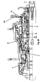
- FIG. 1 shows a multi-speed hub with a gear assembly and a remindsetzbremsmechanismus according to the present invention, which is suitable for use in a bicycle.
- the illustrated construction includes, but is not limited to, a fixed shaft 1 fixed to a bicycle frame, a rotatable drive member 2, a rotatable hub shell 3, a first output clutch 26, a second output clutch 28, an output selector 27, a sprocket 35, a first one Planetary gear 4, a second planetary gear 5 and a coupling element 60th
- the first planetary gear 4 comprises a preferably integrally formed planet carrier, which has a drive-side part 4a and a driven-side part 4b.
- the drive-side part 4a of the planet carrier 4a, 4b acts as a drive part 2.
- the first planetary gear 4 has a first sun gear 23 and a second sun gear 24, both of which are mounted non-displaceably on the fixed shaft 1 in the longitudinal direction.
- the first sun gear 23 may be engaged with at least one first planetary gear 51 and the second sun gear 24 may be engaged with at least one second planetary gear 52, wherein the first planetary gear 51 has a larger diameter than the second planetary gear 52.
- a sun gear clutch 21 and 22 are arranged in each case.
- the sun gear clutches 21 and 22 can be selectively engaged with the fixed shaft 1 so that a drive torque is transmitted or not transmitted.
- the sun gear clutches 21 and 22 and thus the first planetary gear 4 can be operated by means of a control device 8 so that it results in a plurality of gear stages.
- the planetary gear 4 is formed in two stages, that is, has Planetenradpare having planetary gears 51, 52 with different diameters.
- the second planetary gear 5 has at least one planetary gear 55 and a planetary gear carrier, which comprises a drive-side part 5a and a driven-side part 5b.
- the second planetary gear 5 is formed in one stage, so has no planetary gears with different diameters. In addition, it is not controlled by means of a sun gear clutch.
- a roller housing 81 is arranged, which is connected to an output coupling 28, which may be effective on one side, and brake parts 82.
- the output clutch 28 is active, that is, a Drive torque is transmitted, or the brake members 82 are active, that is, a braking torque is transmitted, wherein the brake members 82 are pressed radially outward and thus a braking operation takes place.
- the planet 4a, 4b of the first planetary gear 4 and the planet 5a, 5b of the second planetary gear 5 are preferably formed integrally.
- a clutch mechanism is provided, which is coupled on the output side with the first planetary gear 4 and is adapted to transmit on the one hand a drive torque applied by the driver in the drive direction in response to a selected gear ratio and forward, and on the other hand applied by the driver in the braking direction braking torque regardless of a selected gear stage via a path P1 or BP to transmit and forward to the brake mechanism, so that the resulting braking effect, regardless of the selected gear stage is substantially equal.
- the clutch mechanism comprises a ring gear 10, which in more detail in the FIGS. 2 and 3 is shown, with a drive-side sprocket 9, which is provided on an inner peripheral surface of the ring gear 10 and is adapted to engage at least one driven-side planetary gear 52 of the first planetary gear 4, and a driven-side sprocket assembly 11 a, 11 b, the two axially offset sprockets 11 a, 11 b provided on an inner peripheral surface of the ring gear 10.
- the first ring gear 11 a is provided at the output side end of the ring gear 10, wherein the second ring gear 11 b is the drive side adjacent thereto.
- the projections and the recesses of the sprockets 11a, 11b and 9 of the ring gear 10 are respectively arranged substantially uniformly in the circumferential direction.
- the coupling mechanism comprises the tubular, preferably integrally formed coupling element 60, which can establish an operative connection to the second planetary gear 5 or transmission parts arranged on the output side with respect to the clutch mechanism.
- the coupling element 60 has a first ring gear 12 a, which is provided on an outer peripheral surface at the drive-side end of the coupling member 60 and is adapted to, with the first ring gear 11 a of the ring gear assembly 11 a, 11 b of the ring gear 10 is engaged to step.
- the coupling member 60 has a second ring gear 12 b provided on an inner circumferential surface at the driving-side end of the coupling member 60.
- the projections and the recesses of the sprockets 12a and 12b of the coupling member 60 are respectively disposed substantially uniformly in the circumferential direction.
- the clutch 19 comprises at least one drive pawl DP and / or at least one brake pawl BP.
- the reference numeral 19a denotes a drive pawl DP and a brake pawl BP
- the reference numeral 19b denotes only a brake pawl BP.
- the part 19b of the brake pawls BP is operatively connected to the second ring gear 11b of the ring gear assembly 11a, 11b of the ring gear 10, while the other part is operatively connected to the second ring gear 12b of the coupling member 60.
- the drive pawls DP and the brake pawls BP are active in opposite directions and in the radial direction to the second sprocket 12b of the coupling member 60 strained out.
- a drive pawl DP comprises a steep surface for engagement with the second ring gear 12b of the coupling element 60 in a drive torque transmission.
- the brake pawl BP includes a steep surface for engagement with the second ring gear 12b of the coupling member 60 at a braking torque transmission.
- the steep surface of the drive pawls DP comes in torque-transmitting engagement with rotation of the driven-side part 4b of the Planetenradlys 4a, 4b in the drive direction, that is at a drive torque transmission via the path P1, with the second ring gear 12b of the coupling member 60, while a flattened surface of the brake pawls BP over the second ring gear 12b of the coupling member 60 slides (see FIG FIG. 7 ).
- the steep surface of the brake pawls BP comes with rotation of the output-side part 4b of the planet carrier 4a, 4b in the braking direction with the second Sprocket 12b of the coupling member 60 in moment-transmitting engagement, while a flattened surface of the drive pawls DP slides over the second sprocket 12b of the coupling member 60 (see FIG. 10 ).
- the drive pawls DP and the brake pawls BP are spaced from each other in the circumferential direction and accommodated in respective recesses in the driven-side part 4b of the planetary gear carrier 4a, 4b of the first planetary gear 4. Consequently, a compact and slim construction is possible.
- the path P1 leads from the drive part 2 to the output-side part 4a of the planet carrier 4a, 4b and from there via the coupling 19 to the coupling element 60.
- the path P2 leads from the drive part 2 to the planetary gear 4 and including the planet gears 51, 52, to the ring gear 10 and from this to the coupling element 60th
- Recesses 30 of the first sprocket 11a of the sprocket assembly 11a, 11b of the ring gear 10 are circumferentially larger than in these recesses 30 engaging projections 31 of the first ring gear 12a of the coupling element 60, so that there is a gap d1, as for example in the FIG. 7 is shown.
- the ring gear 10 is thus able to move relative to the coupling member 60 in the circumferential direction. Consequently, in particular, the second toothed rim 11b of the sprocket assembly 11a, 11b can move relative to the second sprocket 12b of the coupling element 60 and align accordingly.
- the second sprocket 11b of the sprocket assembly 11a, 11b of the ring gear 10 has protrusions 45 adapted to deactivate the drive pawls DP and / or the brake pawls BP.
- These projections 45 are arranged, adapted and circumferentially alignable, that the drive pawls DP and / or the brake pawls BP are prevented from momentarily engaging during a drive torque transmission via a path P2 with the second ring gear 12b of the coupling element 60, wherein during a Braking torque transmission via a path P1 engagement of the brake pawls BP with the second ring gear 12b of the coupling element 60 and thus a forwarding of the braking torque to the brake mechanism 8 out is possible.
- the deactivation protrusions 45 are further arranged, adapted and circumferentially alignable such that during drive or braking torque transmission via the path P 1, the drive pawls DP or the brake pawls BP are capable of the second ring gear 12b of the coupling member 60 to engage, so that consequently the transmission of a drive or braking torque is possible.
- annular spring 40 is inserted into an inner circumferential groove on the ring gear 10.
- the annular spring 40 is by means of a hook 41 which is arranged with play in a peripheral recess 42 on the output side part 4b of the planet 4a, 4b of the first planetary gear 4, with this recess 42 mutually engaged.
- the hook 41 extends radially inward from one end of the ring spring 40.
- the annular spring 40 can be in selective operative connection with the ring gear 10 by means of a friction or friction torque which can be built up and removed therebetween.
- the ring gear 10 may be rotated relative to the coupling member 60 by means of the friction torque occurring between the ring gear 10 and the ring spring 40.
- the annular spring 40 rotates due to the arranged in the recess 42 hook 41 with the driving output side part 4b of the planet carrier 4a, 4b of the first planetary gear 4th
- the annular spring 40 operates in the following manner, the function of the annular spring 40 further with reference to FIGS FIGS. 14 to 19 becomes clear.
- the annular spring 40 When the planet carrier 4a, 4b rotates in the drive direction, the annular spring 40 also rotates in the drive direction. Then, the ring gear 10 rotates in the driving direction relative to the coupling member 60 by means of the ring spring 40. In this case, the ring spring 40 widens to the ring gear 10, whereby the friction between the ring spring 40 and the ring gear 10 becomes larger.
- the annular spring 40 When the planet carrier 4a, 4b of the first planetary gear 4 rotates in a direction opposite to the drive direction braking direction, the annular spring 40 also rotates in the braking direction. Then, the ring gear 10 rotates in the braking direction relative to the coupling element 60 by means of the annular spring 40. In this case, the annular spring 40 contracts or contracts, the friction between the annular spring 40 and the ring gear 10 is reduced compared to the drive case.
- the second ring gear 11b of the ring gear 10 may rotate relative to the second ring gear 12b of the coupling member 60 Align the circumferential direction.
- the brake pawls BP may be momentarily engaged with the second ring gear 12b of the coupling member 60.
- the ring gear 10 can rotate relative to the coupling member 60 by friction by means of a friction torque that can be formed between the ring gear 10 and the ring spring 40.
- the coupling element 60 is connected to a shaft of a first output coupling 26 between its drive-side end and its output side end on both sides in engagement.
- the first output coupling 26, which is effective on one side, can for this purpose in a peripheral recess or a passage 61, which is located in the coupling element 60, be arranged, as for example in the FIGS. 4 and 6 is shown.
- Adjacent to the first output coupling 26 is a pawl housing 29.
- the pawl housing 29 is arranged on the output side of the first output coupling 26 and is in operative connection with an inner ring gear of the hub shell 3, the first output coupling 26 and the output end of the coupling element 60.
- the pawl housing 29 engages with the corresponding inner ring gear of the hub shell 3 and is rotated with the hub shell 3.
- the mode of action of such a pawl housing 29 is known to those skilled in the art.
- the coupling member 60 further includes at its driven-side end a ring gear 12 c, which is provided on an inner peripheral surface of the coupling member 60 and is engaged with planetary gears 55 of the second planetary gear 5.
- the coupling element 60 couples the first planetary gear 4 with the second planetary gear 5 or with the clutch mechanism located on the output side of the first planetary gear 4 such that a permanent synchronization between the two planetary gears 4, 5 is achieved.
- the coupling element 60 comprises two different outer diameters R1, R2, which result from an oblique Abtreppung or an oblique offset, wherein the drive-side outer diameter R1 is greater than the output-side outer diameter R2. It will be apparent to those skilled in the art that a large outer diameter corresponds to a large inner diameter and a small outer diameter corresponds to a small inner diameter.
- the gear arrangement has an output selector 27, which can be actuated longitudinally displaceable by means of a control device 8, so that the output takes place either via the first output coupling 26 or via the second output coupling 28.
- FIGS. 7 to 10 schematically show the parts involved in the clutch mechanism, starting from a drive torque transmission with respect to the first gear to a braking torque transmission.
- the FIGS. 7 to 10 are cross sections along a line AA in FIG. 1 ,
- the FIG. 7 shows the clutch mechanism in the state of a drive torque transmission with respect to the first gear.
- the driving output side part 4b of the planet carrier 4a, 4b rotates in the direction of the arrow A.
- the steep surfaces of the drive pawls DP are engaged with the second ring gear 12b of the coupling member 60, while the brake pawls BP with their flattened surfaces on the second ring gear 12b of the Slide coupling element 60, that is, the drive pawls DP are active and the brake pawls BP are not active.
- the hook 41 of the ring spring 40 is engaged with a left wall of the recess 42.
- the annular spring 40 rotates, widening toward the ring gear 10 and expanding toward the ring gear 10.
- the ring gear 10 rotates by means of friction or by means of a friction torque which is built up between the ring gear 10 and the annular spring 40. Since the projections 31 of the first ring gear 12a of the coupling element 60 in the circumferential direction is smaller than the recesses 30 of the first ring gear 11a of the ring gear 10th are, results in each case a gap d1 between them.
- FIG. 8 shows the clutch mechanism, wherein a state of a drive torque transmission with respect to the first gear, that is, starting from the FIG. 7 , a braking torque is applied by a driver.
- the driving output-side part 4b of the planet carrier 4a, 4b now rotates in a direction opposite to the drive direction braking direction, as indicated by the arrow A.
- the drive pawls DP are disengaged from the second sprocket 12b of the coupling element 60.
- the hook 41 of the annular spring 40 engages with a right wall of the recess 42 into engagement.
- the annular spring 40 rotates together with the driven-side part 4b of the planet carrier 4a, 4b.
- FIG. 9 shows the clutch mechanism in a state similar to that in the FIG. 8 shown state follows.
- the ring gear 10 rotates by means of friction between the annular spring 40 and the ring gear 10 relative to the coupling element 60.
- the projections 31 of the coupling element 60 are located in the recesses 30 of the first ring gear assembly 11 a in an intermediate position, that is, are not connected to walls of Recesses 30 in contact.
- FIG. 10 shows the clutch mechanism in a state similar to that in the FIG. 9 shown state follows. Since the ring gear 10 and thus its second ring gear 11b of the sprocket assembly 11a, 11b has rotated and aligned relative to the coupling element 60 and the second ring gear 12b of the coupling element 60, the brake pawls BP now engage with the second ring gear 12b of the coupling element 60 while the drive pawls DP slide with their flattened surfaces over the second sprocket 12b of the coupling element 60, that is, the pawls are active and the drive pawls are not active.
- the projections 31 of the first ring gear 12a of the coupling element 60 are now right-justified in the recesses 30. Since the projections 31 are smaller in the circumferential direction than the recesses 30, there is in each case a gap d2, which corresponds in its order of magnitude d1.
- FIGS. 11 to 14 schematically show the parts involved in the clutch mechanism, starting from a drive torque transmission with respect to the second, third fourth or fifth gear to a braking torque transmission.
- the FIGS. 11 to 14 are cross sections along the line AA in FIG. 1 ,
- the FIG. 11 shows the clutch mechanism in the state of a drive torque transmission. This state corresponds to the drive torque transmission of the second, third, fourth or fifth gear.
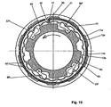
- the driving ring gear 10 rotates in the direction of the arrow A and faster than the output-side part 4b of the planet carrier 4a, 4b.
- the drive torque with respect to the gear stages reaches two to five of the drive part 2 and the drive-side part 4a of the Planetenradlys 4a, 4b via the first planetary gear 4 based on the second planetary gears 52 on the ring gear 10.
- the first sprocket 11a of the sprocket assembly 11a, 11b of the ring gear 10 is left-justified with the first ring gear 12a of the coupling element 60 in drive torque transmission engagement. Since, as already mentioned, the projections 31 of the first ring gear 12a of the coupling element 60 are smaller in the circumferential direction than the recesses 30 of the first ring gear 11a of the ring gear 10, a gap d1 also results here.
- the hook 41 of the annular spring 40 is engaged with the right wall of the recess 42 in engagement.
- both the driving pawls DP nor the brake pawls BP are in torque-transmitting communication with the second ring gear 12b of the coupling member 60, that is, both the driving pawls DP and the brake pawls BP are not active.
- the FIG. 12 shows the clutch mechanism, wherein a state of a drive torque transmission with respect to the second, third, fourth or fifth gear, that is, starting from the FIG. 11 , a braking torque is applied by a driver.
- the driving output side part 4 b of the planet carrier 4 a, 4 b is rotated in the braking direction, which is indicated by the arrow A.
- the ring gear 10 rotates faster than the output side part 4b of the planet carrier 4a, 4b.
- the hook 41 of the annular spring 40 engages with the left wall of the recess 42, since the output side part 4b of the planet 4a, 4b with respect FIG. 12 turns counterclockwise. Now, the annular spring 40 rotates with the output-side part 4b of the planet carrier 4a, 4b.
- FIG. 13 shows the clutch mechanism in a state similar to that in the FIG. 12 shown state follows.
- the ring gear 10 rotates counterclockwise relative to the coupling member 60 by friction between the ring spring 40 and the ring gear 10.
- the pawls BP begin to engage the second ring gear 12b of the coupling member 60.
- the drive pawls DP slide with their flattened surfaces over the second ring gear 12b of the coupling element 60, without entering into a drive torque transmission with this.
- the projections 31 of the coupling element 60 are still in an intermediate position in the recesses 30 of the ring gear 10th
- FIG. 14 shows the clutch mechanism in a state similar to that in the FIG. 13 shown state follows. Since the ring gear 10 rotates faster than the output-side part 4b of the planet carrier 4a, 4b, the projections 31 of the coupling element 60 now come into contact with the right-hand walls of the recesses 30 of the ring gear. The ring gear 10 rotates with the ring spring 40. The ring gear 10 rotates relative to the coupling member 60, and thus the second ring gear 11b of the ring gear assembly 11a, 11b of the ring gear 10 rotates relative to the second ring gear 12b of the coupling member 60.
- the brake pawls BP stand now engaged with the second ring gear 12b of the coupling member 60 so that the braking torque can be forwarded by means of the coupling element 60.
- the drive pawls DP slide over the second ring gear 12b of the coupling member 60 without engaging in torque transfer engagement therewith.
- a path DP1 in the FIG. 15 represents the transmission path of the drive torque with respect to the first gear from the sprocket 35 via the gear assembly to the hub shell 3.
- a path DP2 in the FIG. 16 represents the transmission path of the drive torque with respect to the second gear from the sprocket 35 via the gear assembly to the hub shell 3.
- a path DP3 in the FIG. 17 represents the transmission path of the drive torque with respect to the third gear from the sprocket 35 via the gear assembly to the hub shell 3.
- a path DP4 in the FIG. 18 represents the transmission path of the drive torque with respect to the fourth gear from the sprocket 35 via the gear assembly to the hub shell 3.
- a path DP5 in the FIG. 19 represents the transmission path of the drive torque with respect to the fifth gear from the sprocket 35 via the gear assembly to the hub shell 3.
- the character "-" denotes a state in which the clutches are not in the operating position, that is, transmit no drive torque.
- the character “0” indicates a state in which the clutches are in the operating position, that is, transmitting a drive torque.
- the second output clutch 28 transmits a drive torque whenever the drive torque takes a path via the second planetary gear 5.
- the character "X” denotes a state in which the second output clutch 28 transmits the drive torque
- the character “n” denotes a state in which the second output clutch 28 transmits no drive torque.
- the clutch mechanism makes it possible that regardless of the selected gear stage, the braking torque is always transmitted to the brake mechanism 8 via the same path P1 or BP1.
- the resulting braking effect is thus not influenced by the gear, from which the driver applies a braking torque. Consequently, the braking process for the driver is more comfortable and safer.
- the entire braking torque transmission path BP1 from the sprocket 35 to the brake mechanism 8 is shown in FIG FIG. 20 shown.
- the braking torque transmission path BP 1 substantially corresponds to the torque transmission path of the first speed stage, but does not lead via the second output clutch 28 to the hub shell 3, but via the brake mechanism 8.
- the structure described above further enables the first planetary gear 4 and the second planetary gear 5 and the clutch mechanism operatively connected to the planetary gear 5 to be coupled together so as to achieve permanent synchronization between the two. Consequently, the gear change is more comfortable for a driver, which at the same time improves the driving feeling during the gear change. It is also advantageous that the second planetary gear 5 does not have to be controlled consuming by means of a mechanism that usually consists of controlled by a control device Sonnenradkupplept or a drive side of this planetary gear complicated coupling mechanism. All this is possible, although the structure described is simple, compact, slim and still reliable in operation.
- the embodiment described above comprises two planetary gears.
- the invention is not limited to two planetary gears, but may be applied to three or more planetary gears.
- the invention is not limited to a first two-stage and a second single-stage planetary gear. Rather, the number, the frequency and the positioning of the planetary gear can be adapted to the respective requirements, such as the number of gear ratios, ratio / reduction gear, etc. Consequently, the braking torque path may be other than that of the first speed stage.
- the components described as preferably in one piece can also be designed in several parts, if this should be necessary.
Description
Die vorliegende Erfindung bezieht sich auf eine Getriebeanordnung für eine Mehrgangnabe, beispielsweise für ein Fahrrad, und insbesondere auf eine Getriebeanordnung mit zumindest einem ersten und einem zweiten Planetengetriebe sowie einem Rücktrittbremsmechanismus.The present invention relates to a transmission assembly for a multi-speed hub, for example, for a bicycle, and more particularly to a transmission assembly having at least a first and a second planetary gear and a coaster brake mechanism.
Ein Fahrradgetriebe für eine Dreigangnabe mit einem Planetengetriebe und einem Rücktrittbremsmechanismus ist beispielsweise in der
Ein Fahrradgetriebe für eine Fünfgangnabe mit einem Rücktrittbremsmechanismus ist beispielsweise aus der
Aus der
Es ist eine Aufgabe der vorliegenden Erfindung, eine Getriebeanordnung mit einem Rücktrittbremsmechanismus für eine Mehrgangnabe zu verbessern. Insbesondere soll der Bremsvorgang für einen Fahrer sicherer und angenehmer erfolgen und eine einfache, kompakte, einen schlanken Aufbau aufweisende Getriebeanordnung geschaffen werden, die trotzdem zuverlässig im Betrieb ist.It is an object of the present invention to improve a transmission assembly with a multi-speed hub coaster brake mechanism. In particular, the braking process for a driver should be safer and more pleasant and a simple, compact, slim design having gear assembly to be created, which is still reliable in operation.
Des Weiteren soll der Gangwechsel für einen Fahrer angenehmer erfolgen und somit das Fahrgefühl während des Gangwechsels verbessert werden.Furthermore, the gear change for a driver should be made more pleasant and thus the driving feeling during the gear change can be improved.
Die Aufgabe wird durch eine Getriebeanordnung, wie durch den unabhängigen Anspruch 1 beschrieben ist, gelöst, wobei zweckmäßige Ausführungsformen durch die Merkmale der Unteransprüche beschrieben sind.The object is achieved by a gear arrangement as described by the independent claim 1, wherein expedient embodiments are described by the features of the subclaims.
Vorgesehen ist eine Getriebeanordnung für eine Mehrgangnabe mit Rücktrittbremsmechanismus, insbesondere für ein Fahrrad, die im Wesentlichen zumindest ein erstes Planetengetriebe und ein zweites Planetengetriebe, sowie einen Rücktrittbremsmechanismus aufweist. Das zumindest erste Planetengetriebe kann mit dem zweiten Planetengetriebe gekoppelt werden. Außerdem ist ein Kupplungsmechanismus bereitgestellt, der abtriebsseitig von dem ersten Planetengetriebe mit diesem koppelbar ist und dazu geeignet ist, einerseits ein vom Fahrer in Antriebsrichtung aufgebrachtes Antriebsmoment in Abhängigkeit einer gewählten Gangstufe, d.h. eines gewählten Ganges zu übertragen und weiterzuleiten, und andererseits ein vom Fahrer in Bremsrichtung aufgebrachtes Bremsmoment unabhängig von einer gewählten Gangstufe über einen einzigen Pfad (BP 1) zu übertragen und zu dem Bremsmechanismus hin weiterzuleiten, so dass die resultierende Bremswirkung unabhängig von der gewählten Gangstufe im Wesentlichen gleich ist. Der Kupplungsmechanismus umfasst ferner zumindest zwei gegenläufig aktive Klinken, welche an einem Planetenradträger des ersten Planetengetriebes bereitgestellt sind.Provided is a transmission arrangement for a multi-speed hub with coaster brake mechanism, in particular for a bicycle, which has substantially at least a first planetary gear and a second planetary gear, and a Rücktrittbremsmechanismus. The at least first planetary gear can be coupled to the second planetary gear. In addition, a clutch mechanism is provided, which is the output side of the first planetary gear coupled to this and is adapted, on the one hand applied by the driver in the drive direction drive torque in response to a selected gear ratio, i. a selected gear to transmit and forward, and on the other hand to transmit a brake applied by the driver in the braking direction regardless of a selected gear on a single path (BP 1) and forward to the braking mechanism, so that the resulting braking effect regardless of the selected gear in Is essentially the same. The clutch mechanism further comprises at least two counter-active pawls which are provided on a planet carrier of the first planetary gear.
Wie es Fachleuten ersichtlich ist, umfasst ein Planetengetriebe im Wesentlichen, aber nicht einschränkend, zumindest ein um eine feststehende Welle einer Mehrgangnabe herum angeordnetes Sonnenrad, mit dem zumindest einen Sonnenrad in Eingriff tretende Planetenräder, einen die Planetenräder tragenden Planetenradträger und üblicherweise ein mit den Planetenrädern in Eingriff stehendes Hohlrad und optional zumindest eine zwischen dem zumindest einen Sonnenrad und der feststehenden Welle angeordnete Sonnenradkupplung, die so angeordnet und ausgelegt ist, dass sie mittels einer Steuereinrichtung betätigbar ist. Die erfmdungsgemäße Getriebeanordnung kann in eine Mehrgangnabe involviert werden, die im Wesentlichen, aber nicht einschränkend, die vorstehend genannte feststehende Welle, einen Antreiber und eine Nabenhülse umfasst, die beide drehbar auf der feststehenden Welle abgestützt sind.As will be appreciated by those skilled in the art, a planetary gear includes, but is not limited to, at least one sun gear disposed about a fixed shaft of a multi-speed hub, planetary gears engaging at least one sun gear, a planet carrier supporting the planet gears, and usually one with the planetary gears Engaging ring gear and optionally at least one arranged between the at least one sun gear and the fixed shaft sun gear, which is arranged and designed so that it can be actuated by means of a control device. The inventive gear assembly may be involved in a multi-speed hub which includes, but is not limited to, the aforementioned fixed shaft, a driver and a hub shell, both of which are rotatably supported on the fixed shaft.
Bei einer vorteilhaften Ausgestaltung weist die Getriebeanordnung zwei Planetengetriebe auf, die in axialer Richtung voneinander beanstandet sind. Dabei ist das erste Planetengetriebe zweistufig ausgebildet, wobei die antriebsseitigen Planetenräder einen größeren Durchmesser als die abtriebsseitigen Planetenräder aufweisen.In an advantageous embodiment, the gear arrangement on two planetary gear, which are spaced apart from each other in the axial direction. In this case, the first planetary gear is formed in two stages, wherein the drive-side planetary gears have a larger diameter than the output-side planetary gears.
Vorzugsweise umfasst der Kupplungsmechanismus ein Hohlrad mit einem antriebsseitigen Zahnkranz, der an einer inneren Umfangsfläche des Hohlrads bereitgestellt ist und dazu geeignet ist, mit zumindest einem abtriebsseitigen Planetenrad des ersten Planetengetriebes in Eingriff zu treten, und einer abtriebsseitigen Zahnkranzanordnung, die zwei in axialer Richtung versetzte Zahnkränze umfasst, die an einer inneren Umfangsfläche des Hohlrads bereitgestellt sind.Preferably, the clutch mechanism includes a ring gear having a drive side sprocket provided on an inner peripheral surface of the ring gear and adapted to engage at least one output side planetary gear of the first planetary gear and an output side sprocket assembly comprising two axially offset gear rings includes, which are provided on an inner circumferential surface of the ring gear.
Des Weiteren umfasst der Kupplungsmechanismus ein röhrenförmiges Kopplungselement, das eine Wirkverbindung zum zweiten Planetengetriebe herstellen kann. Das Kopplungselement weist einen ersten Zahnkranz auf, der auf einer äußeren Umfangsfläche am antriebsseitigen Ende des Kopplungselements bereitgestellt ist und dazu geeignet ist, mit einem ersten Zahnkranz der Zahnkranzanordnung des Hohlrads in Eingriff zu treten. Außerdem hat das Kopplungselement einen zweiten Zahnkranz, der auf einer inneren Umfangsfläche am antriebsseitigen Ende des Kopplungselements bereitgestellt ist.Furthermore, the clutch mechanism comprises a tubular coupling element that can make an operative connection to the second planetary gear. The coupling member has a first sprocket provided on an outer peripheral surface at the drive side end of the coupling member and adapted to engage with a first sprocket of the sprocket assembly of the ring gear. In addition, the coupling member has a second sprocket provided on an inner peripheral surface at the drive-side end of the coupling member.
Außerdem umfasst der Kupplungsmechanismus einen abtriebsseitigen Teil eines Planetenradträgers des ersten Planetengetriebes, der dazu geeignet ist, mittels zumindest einer Antriebsklinke und/oder zumindest einer Bremsklinke in selektiver Momentübertragungsverbindung mit dem zweiten Zahnkranz des Kopplungselements zu stehen.In addition, the clutch mechanism comprises a driven-side part of a planet carrier of the first planetary gear, which is adapted to be by means of at least one drive pawl and / or at least one brake pawl in selective torque-transmitting connection with the second ring gear of the coupling element.
Vorzugsweise sind die zumindest eine Antriebsklinke und die zumindest eine Bremsklinke in jeweiligen peripheren Aussparungen am abtriebsseitigen Teil des Planetenradträgers des ersten Planetengetriebes gegenläufig bereitgestellt und in radialer Richtung zu dem zweiten Zahnkranz des Kopplungselements hin gespannt. Bei einer vorteilhaften Ausgestaltung können sowohl die zumindest eine Antriebsklinke als auch die zumindest eine Bremsklinke jeweils eine steile Fläche, die dazu geeignet ist, mit dem zweiten Zahnkranz des Kopplungselements in Eingriff zu treten, und eine abgeflachte Fläche umfassen, die nicht in Momentübertragungseingriff gelangt.Preferably, the at least one drive pawl and the at least one brake pawl in respective peripheral recesses on the output-side part of the planet carrier of the first planetary gear provided in opposite directions and stretched in the radial direction to the second ring gear of the coupling element out. In an advantageous embodiment, both the at least one drive pawl and the at least one brake pawl can each comprise a steep surface, which is adapted to engage with the second ring gear of the coupling element, and a flattened surface, which does not come into torque-transmitting engagement.
Des Weiteren ist vorzugsweise eine Ringfeder so bereitgestellt, dass der abtriebsseitige Teil des Planetenradträgers des ersten Planetengetriebes mit dem Hohlrad in mittels dieser Ringfeder Wirkverbindung gebracht werden kann. Die Ringfeder ist in einer inneren Umfangsnut des Hohlrads bereitgestellt.Furthermore, an annular spring is preferably provided in such a way that the output-side part of the planetary gear carrier of the first planetary gear can be brought into operative connection with the ring gear by means of this annular spring. The annular spring is provided in an inner circumferential groove of the ring gear.
Vorzugsweise ist der antriebsseitige Teil des Planetenradträgers des ersten Planetengetriebes dazu geeignet, als Antriebsteil zu wirken.Preferably, the drive-side part of the planet carrier of the first planetary gear is adapted to act as a drive part.
Bei einer vorteilhaften Ausgestaltung sind Vertiefungen des ersten Zahnkranzes der Zahnkranzanordnung des Hohlrads in Umfangsrichtung größer als in diese Vertiefungen eingreifende Vorsprünge des ersten Zahnkranzes des Kopplungselements, so dass sich ein Zwischenraum ergibt. Folglich können sie diese Elemente relativ zu einander in Umfangsrichtung bewegen.In an advantageous embodiment, recesses of the first ring gear of the ring gear arrangement of the ring gear in the circumferential direction are greater than in these recesses engaging projections of the first ring gear of the coupling element, so that there is a gap. Consequently, they can move these elements relative to each other in the circumferential direction.
Das Hohlrad, insbesondere der zweite Zahnkranz der Zahnkranzanordnung des Hohlrads ist dazu geeignet, sich in Abhängigkeit der Drehrichtung relativ zu dem Kopplungselement, insbesondere zu dem zweiten Zahnkranz des Kopplungselements zu drehen, wobei dadurch eine Ausrichtung der beiden Elemente erreicht werden kann.The ring gear, in particular the second ring gear of the ring gear arrangement of the ring gear is adapted to rotate in dependence on the direction of rotation relative to the coupling element, in particular to the second ring gear of the coupling element, thereby alignment of the two elements can be achieved.
Der zweite Zahnkranz der Zahnkranzanordnung des Hohlrads weist Vorsprünge auf, die dazu geeignet sind, die zumindest eine Bremsklinke zu deaktivieren, wobei diese so angeordnet, angepasst und ausrichtbar sind, dass die zumindest eine Bremsklinke davon abgehalten wird, während einer Antriebsmomentübertragung über einen Pfad P2 mit dem zweiten Zahnkranz des Kopplungselements in Momentübertragungseingriff zu gelangen, wobei während einer Bremsmomentübertragung über einen Pfad P1 ein Eingriff der zumindest einen Bremsklinke mit dem zweiten Zahnkranz des Kopplungselements möglich ist.The second ring gear of the ring gear arrangement of the ring gear has projections which are adapted to deactivate the at least one brake pawl, which are arranged, adapted and alignable, that the at least one brake pawl is prevented from, during a drive torque transmission via a path P2 with the second sprocket of the coupling element in torque transfer engagement, wherein during a braking torque transmission via a path P1 engagement of the at least one brake pawl with the second sprocket of the coupling element is possible.
Die Vorsprünge zum Deaktivieren der zumindest einen Bremsklinke sind so angeordnet, angepasst und ausrichtbar, dass während einer Antriebs- oder Momentübertragung über einen Pfad P1 die zumindest eine Antriebsklinke und/oder die zumindest eine Bremsklinke in der Lage ist, mit dem zweiten Zahnkranz des Kopplungselements in Momentübertragungseingriff zu treten.The projections for deactivating the at least one brake pawl are arranged, adapted and alignable such that during a drive or torque transmission via a path P1 the at least one drive pawl and / or the at least one brake pawl is capable of engaging with the second cogwheel of the coupling element in FIG Moment transfer intervention.
Die vorstehend genannte Ringfeder steht mittels eines Hakens, der mit Spiel in einer peripheren Ausnehmung am abtriebsseitigen Teil des Planetenradträgers des ersten Planetengetriebes angeordnet ist, mit dieser Ausnehmung wechselseitig in Eingriff. Bei einer bevorzugen Ausführungsform ist die Ringfeder dazu geeignet, in Abhängigkeit einer Drehrichtung wahlweise zu expandieren bzw. sich auszuweiten oder zu kontrahieren bzw. sich zusammenzuziehen, wobei eine Reibung zwischen der Ringfeder und dem Hohlrad vergrößert oder verkleinert werden kann. Dies kann für einen Ausrichtvorgang des Hohlrades mit dem Kopplungselement erfolgen, insbesondere für eine Ausrichtung des zweiten Zahnkranzes der Zahnkranzanordnung des Hohlrads mit der zweiten Zahnkranzanordnung des Kopplungselements.The above ring spring is by means of a hook, which is arranged with play in a peripheral recess on the output side part of the planet carrier of the first planetary gear, with this recess mutually engaged. In a preferred embodiment, the annular spring is adapted, depending on a direction of rotation, optionally to expand or to expand or contract or contract, wherein a friction between the annular spring and the ring gear can be increased or decreased. This can be done for an alignment process of the ring gear with the coupling element, in particular for an alignment of the second ring gear of the ring gear arrangement of the ring gear with the second ring gear arrangement of the coupling element.
Des Weiteren kann die Getriebeanordnung eine Abtriebswahleinrichtung aufweisen, die mittels einer Steuereinrichtung längsverschieblich betätigbar ist, so dass der Abtrieb entweder über eine erste Abtriebskupplung oder über eine zweite Abtriebskupplung erfolgt.Furthermore, the transmission arrangement can have an output selection device which can be longitudinally displaceably actuated by means of a control device, so that the output takes place either via a first output clutch or via a second output clutch.
Abtriebsseitig von dem zweiten Planetengetriebe sind Bremsteile mit einem Rollengehäuse verbunden, die während eines Bremsvorgangs radial nach Außen gedrückt werden.On the output side of the second planetary gear brake parts are connected to a roller housing, which are pressed radially outward during a braking operation.
Des Weiteren kann jeweils eine Sonnenradkupplung zwischen den Planetenrädern der Planetengetriebe und der feststehenden Welle angeordnet sein. Vorzugsweise ist jeweils eine Sonnenradkupplung zwischen der feststehenden Welle und den Sonnenrädern des ersten Planetengetriebes angeordnet.Furthermore, in each case a sun gear between the planetary gears of the planetary gear and the fixed shaft can be arranged. Preferably, a sun gear between the fixed shaft and the sun gears of the first planetary gear is arranged in each case.
Das Kopplungselement ist dazu geeignet, die zumindest zwei Planetengetriebe so miteinander zu Koppeln bzw. so eine Wirkverbindung zwischen den zumindest zwei Planetengetrieben zu ermöglichen, dass eine permanente Synchronisation zwischen den zumindest zwei Planetengetrieben erreicht wird.The coupling element is suitable for coupling the at least two planetary transmissions with one another or for enabling an operative connection between the at least two planetary transmissions so that a permanent synchronization between the at least two planetary transmissions is achieved.
Die Steuervorrichtung kann so betätigt werden, dass durch Steuern der vorzugsweise zwei Sonnenradkupplungen am ersten Planetengetriebe und der Abtriebswahleinrichtung eine Vielzahl von Gängen zur Verfügung gestellt wird.The control device may be actuated to provide a plurality of speeds by controlling the preferably two sun gear clutches on the first planetary gear and the output selector.
Bei einer vorteilhaften Ausgestaltung ist das erste Planetengetriebe zweistufig und das zweite Planetengetriebe einstufig ausgebildet, so dass sich ein Fünfganggetriebe ergibt.In an advantageous embodiment, the first planetary gear is two-stage and the second planetary gear formed in one stage, so that there is a five-speed gearbox.
Der eine Bremsmomentübertragungspfad entspricht vorzugsweise im Wesentlichen dem Übertragungspfad der ersten Gangstufe, führt jedoch nicht über die zweite Abtriebskupplung zur Nabenhülse, sondern über den Bremsmechanismus.The one brake torque transmission path preferably corresponds essentially to the transmission path of the first gear, but does not lead via the second output clutch to the hub shell, but via the brake mechanism.
Andere Aufgaben, Vorteile und nützliche Merkmale der vorliegenden Erfindung werden Fachleuten aus der nachfolgenden detaillierten Beschreibung ersichtlich, die in Verbindung mit den beigefügten Zeichnungen eine bevorzugte Ausführungsform der vorliegenden Erfindung offenbart.Other objects, advantages and useful features of the present invention will become apparent to those skilled in the art from the following detailed description, which, taken in conjunction with the annexed drawings, discloses a preferred embodiment of the present invention.
- Figur 1FIG. 1
- ist ein Teillängsschnitt einer in eine Mehrgangnabe eines Fahrrads eingebauten Getriebeanordnung mit einem Rücktrittbremsmechanismus gemäß der vorliegenden Erfindung;Figure 11 is a partial longitudinal section of a gear assembly incorporated into a multi-speed hub of a bicycle with a coaster brake mechanism according to the present invention;
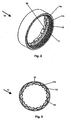
- Figur 2FIG. 2
- ist eine perspektivische Ansicht eines Hohlrads der Getriebeanordnung gemäß der vorliegenden Erfindung;Fig. 12 is a perspective view of a ring gear of the gear assembly according to the present invention;
- Figur 3FIG. 3
- ist eine Draufsicht des Hohlrades der Getriebeanordnung gemäß der vorliegenden Erfindung;Fig. 12 is a plan view of the ring gear of the gear assembly according to the present invention;
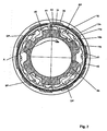
- Figur 4FIG. 4
- ist eine perspektivische Ansicht eines Kopplungselements der Getriebeanordnung gemäß der vorliegenden Erfindung;is a perspective view of a coupling element of the transmission assembly according to the present invention;
- Figur 5FIG. 5
- ist eine Vorderansicht des Kopplungselements der Getriebeanordnung gemäß der vorliegenden Erfindung;is a front view of the coupling element of the transmission assembly according to the present invention;
- Figur 6FIG. 6
- ist eine Seitenansicht des Kopplungselements der Getriebeanordnung gemäß der vorliegenden Erfindung;is a side view of the coupling element of the transmission assembly according to the present invention;
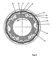
- Figur 7FIG. 7
- ist eine schematische Darstellung eines Querschnitts durch einen Kupplungsmechanismus der Getriebeanordnung gemäß der vorliegenden Erfindung, in einer ersten Gangstufe;is a schematic representation of a cross section through a clutch mechanism of the transmission assembly according to the present invention, in a first gear stage;
- Figur 8FIG. 8
- ist eine schematische Darstellung eines Querschnitts durch den Kupplungsmechanismus der Getriebeanordnung gemäß der vorliegenden Erfindung, wenn ausgehend von der ersten Gangstufe ein Bremsmoment aufgebracht wird;is a schematic representation of a cross section through the clutch mechanism of the transmission assembly according to the present invention, when starting from the first gear stage, a braking torque is applied;
- Figur 9FIG. 9
- ist eine schematische Darstellung eines Querschnitts durch den Kupplungsmechanismus der Getriebeanordnung gemäß der vorliegenden Erfindung, wenn ausgehend von der ersten Gangstufe ein Bremsmoment aufgebracht wird;is a schematic representation of a cross section through the clutch mechanism of the transmission assembly according to the present invention, when starting from the first gear stage, a braking torque is applied;
- Figur 10FIG. 10
- ist eine schematische Darstellung eines Querschnitts durch den Kupplungsmechanismus der Getriebeanordnung gemäß der vorliegenden Erfindung, wenn ausgehend von der ersten Gangstufe ein Bremsmoment aufgebracht wird;is a schematic representation of a cross section through the clutch mechanism of the transmission assembly according to the present invention, when starting from the first gear stage, a braking torque is applied;
- Figur 11FIG. 11
- ist eine schematische Darstellung eines Querschnitts durch den Kupplungsmechanismus der Getriebeanordnung gemäß der vorliegenden Erfindung, in der zweiten, dritten, vierten oder fünften Gangstufe;Fig. 12 is a schematic illustration of a cross section through the clutch mechanism of the transmission assembly according to the present invention, in the second, third, fourth or fifth gear stage;
- Figur 12FIG. 12
- ist eine schematische Darstellung eines Querschnitts durch den Kupplungsmechanismus der Getriebeanordnung gemäß der vorliegenden Erfindung, wenn ausgehend von der zweiten, dritten, vierten oder fünften Gangstufe ein Bremsmoment aufgebracht wird;is a schematic representation of a cross section through the clutch mechanism of the transmission assembly according to the present invention, when starting from the second, third, fourth or fifth gear, a braking torque is applied;
- Figur 13FIG. 13
- ist eine schematische Darstellung eines Querschnitts durch den Kupplungsmechanismus der Getriebeanordnung gemäß der vorliegenden Erfindung, wenn ausgehend von der zweiten, dritten, vierten oder fünften Gangstufe ein Bremsmoment aufgebracht wird;is a schematic representation of a cross section through the clutch mechanism of the transmission assembly according to the present invention Invention, when starting from the second, third, fourth or fifth gear, a braking torque is applied;
- Figur 14FIG. 14
- ist eine schematische Darstellung eines Querschnitts durch den Kupplungsmechanismus der Getriebeanordnung gemäß der vorliegenden Erfindung, wenn ausgehend von der zweiten, dritten, vierten oder fünften Gangstufe ein Bremsmoment aufgebracht wird;is a schematic representation of a cross section through the clutch mechanism of the transmission assembly according to the present invention, when starting from the second, third, fourth or fifth gear, a braking torque is applied;
- Figur 15FIG. 15
- ist ein Teillängsschnitt der Getriebeanordnung gemäß der vorliegenden Erfindung, mit dargestelltem Antriebsmomentübertragungspfad des ersten Gangs;FIG. 12 is a partial longitudinal section of the transmission assembly according to the present invention with the first-speed drive torque transmission path illustrated; FIG.
- Figur 16FIG. 16
- ist ein Teillängsschnitt der Getriebeanordnung gemäß der vorliegenden Erfindung, mit dargestelltem Antriebsmomentübertragungspfad des zweiten Gangs;Figure 11 is a partial longitudinal section of the transmission assembly according to the present invention with the second-speed drive torque transmission path illustrated;
- Figur 17FIG. 17
- ist ein Teillängsschnitt der Getriebeanordnung gemäß der vorliegenden Erfindung, mit dargestelltem Antriebsmomentübertragungspfad des dritten Gangs;Figure 11 is a partial longitudinal section of the transmission assembly according to the present invention, with the third speed drive torque transmission path illustrated;
- Figur 18FIG. 18
- ist ein Teillängsschnitt der Getriebeanordnung gemäß der vorliegenden Erfindung, mit dargestelltem Antriebsmomentübertragungspfad des vierten Gangs;FIG. 12 is a partial longitudinal section of the transmission assembly according to the present invention, with the fourth speed drive torque transmission path illustrated; FIG.
- Figur 19FIG. 19
- ist ein Teillängsschnitt der Getriebeanordnung gemäß der vorliegenden Erfindung, mit dargestelltem Antriebsmomentübertragungspfad des fünften Gangs;FIG. 12 is a partial longitudinal section of the transmission assembly according to the present invention, with the drive gear transmission path of the fifth speed illustrated; FIG.
- Figur 20FIG. 20
- ist ein Teillängsschnitt der Getriebeanordnung gemäß der vorliegenden Erfindung ist, mit dargestelltem Bremsmomentübertragungspfad;Figure 11 is a partial longitudinal section of the transmission assembly according to the present invention, with brake torque transmission path illustrated;
Nachfolgend wird unter Bezugnahme auf die
Die
Das erste Planetengetriebe 4 umfasst einen vorzugsweise einstückig ausgebildeten Planetenradträger, der einen antriebsseitigen Teil 4a und einen abtriebsseitigen Teil 4b aufweist. Im vorliegenden Ausführungsbeispiel wirkt der antriebsseitige Teil 4a des Planetenradträgers 4a, 4b als Antriebsteil 2. Das erste Planetengetriebe 4 weist ein erstes Sonnenrad 23 und ein zweites Sonnenrad 24 auf, die beide auf der feststehenden Welle 1 in Längsrichtung unverschieblich gelagert sind. Das erste Sonnenrad 23 kann mit zumindest einem ersten Planetenrad 51 und das zweite Sonnenrad 24 kann mit zumindest einem zweiten Planetenrad 52 in Eingriff gebracht werden, wobei das erste Planetenrad 51 einen größeren Durchmesser als das zweite Planetenrad 52 aufweist. Zwischen den Sonnenrädern 23 und 24 und der feststehenden Welle 1 ist jeweils eine Sonnenradkupplung 21 und 22 angeordnet. Die Sonnenradkupplungen 21 und 22 können selektiv mit der feststehenden Welle 1 so in Eingriff gebracht werden, dass ein Antriebsmoment übertragen oder nicht übertragen wird. Die Sonnenradkupplungen 21 und 22 und somit das erste Planetengetriebe 4 können mittels einer Steuereinrichtung 8 so betätigt werden, dass daraus eine Vielzahl von Gangstufen resultiert. Das Planetengetriebe 4 ist zweistufig ausgebildet, das heißt, hat Planetenradpaare, die Planetenräder 51, 52 mit unterschiedlichen Durchmessern aufweisen.The first planetary gear 4 comprises a preferably integrally formed planet carrier, which has a drive-
Das zweite Planetengetriebe 5 weist zumindest ein Planetenrad 55 und einen Planetenradträger auf, der einen antriebsseitigen Teil 5a und einen abtriebsseitigen Teil 5b umfasst. Das zweite Planetengetriebe 5 ist einstufig ausgebildet, hat also keine Planetenräder mit unterschiedlichem Durchmesser. Außerdem wird es nicht mittels einer Sonnenradkupplung gesteuert. Zwischen dem abtriebsseitigen Teil 5b des Planetenradträgers 5a, 5b des zweiten Planetengetriebes 5 und der Nabenhülse 3 ist ein Rollengehäuse 81 angeordnet, das mit einer Abtriebskupplung 28, die einseitig wirksam ausgebildet sein kann, und Bremsteilen 82 in Verbindung steht. In Abhängigkeit von der Drehrichtung des Planetenradträgers 5a, 5b ist entweder die Abtriebskupplung 28 aktiv, das heißt, ein Antriebsmoment wird übertragen, oder die Bremsteile 82 sind aktiv, das heißt, ein Bremsmoment wird übertragen, wobei die Bremsteile 82 radial nach Außen gedrückt werden und somit ein Bremsvorgang stattfindet. Der Planetenradträger 4a, 4b des ersten Planetengetriebes 4 sowie der Planetenradträger 5a, 5b des zweiten Planetengetriebes 5 sind vorzugsweise einstückig ausgebildet.The second
Des Weiteren ist ein Kupplungsmechanismus bereitgestellt, der abtriebsseitig mit dem ersten Planetengetriebe 4 gekoppelt ist und dazu geeignet ist, einerseits ein vom Fahrer in Antriebsrichtung aufgebrachtes Antriebsmoment in Abhängigkeit einer gewählten Gangstufe zu übertragen und weiterzuleiten, und andererseits ein vom Fahrer in Bremsrichtung aufgebrachtes Bremsmoment unabhängig von einer gewählten Gangstufe über einen Pfad P1 bzw. BP zu übertragen und zu dem Bremsmechanismus weiterzuleiten, so dass die resultierende Bremswirkung unabhängig von der gewählten Gangstufe im Wesentlichen gleich ist.Furthermore, a clutch mechanism is provided, which is coupled on the output side with the first planetary gear 4 and is adapted to transmit on the one hand a drive torque applied by the driver in the drive direction in response to a selected gear ratio and forward, and on the other hand applied by the driver in the braking direction braking torque regardless of a selected gear stage via a path P1 or BP to transmit and forward to the brake mechanism, so that the resulting braking effect, regardless of the selected gear stage is substantially equal.
Der Kupplungsmechanismus umfasst ein Hohlrad 10, welches detaillierter in den
Des Weiteren umfasst der Kupplungsmechanismus das röhrenförmige, bevorzugt einstückig ausgebildete Kopplungselement 60, das eine Wirkverbindung zu dem zweiten Planetengetriebe 5 bzw. bezüglich des Kupplungsmechanismus abtriebsseitig angeordneten Getriebeteilen herstellen kann. Das Kopplungselement 60, das detaillierter in den
In den Kupplungsmechanismus involviert ist auch der abtriebsseitige Teil 4b des Planetenradträgers 4a, 4b des ersten Planetengetriebes 4, der mittels einer Kupplung 19 in selektiver Momentübertragungsverbindung mit dem zweiten Zahnkranz 12b des Kopplungselements 60 steht. Die Kupplung 19 umfasst zumindest eine Antriebsklinke DP und/oder zumindest eine Bremsklinke BP. Das Bezugszeichen 19a kennzeichnet eine Antriebsklinke DP und eine Bremsklinke BP, wohingegen das Bezugszeichen 19b lediglich eine Bremsklinke BP kennzeichnet. Mit anderen Worten heißt das, dass die Antriebsklinken DP einklinkig ausgebildet sind, während die Bremsklinken BP zweiklinkig ausgebildet sind, vorzugsweise einstückig. Der Teil 19b der Bremsklinken BP steht mit dem zweiten Zahnkranz 11b der Zahnkranzanordnung 11a, 11b des Hohlrads 10 in Wirkverbindung, während der andere Teil mit dem zweiten Zahnkranz 12b des Kopplungselements 60 in Wirkverbindung steht.Also involved in the clutch mechanism is the output-
Die Antriebsklinken DP und die Bremsklinken BP sind gegenläufig aktiv und in radialer Richtung zu dem zweiten Zahnkranz 12b des Kopplungselements 60 hin gespannt. Wie beispielsweise in der
Die steile Fläche der Antriebsklinken DP kommt bei Drehung des abtriebsseitigen Teils 4b des Planetenradträgers 4a, 4b in Antriebsrichtung, das heißt bei einer Antriebsmomentübertragung über den Pfad P1, mit dem zweiten Zahnkranz 12b des Kopplungselements 60 in Momentübertragungseingriff, während eine abgeflachte Fläche der Bremsklinken BP über den zweiten Zahnkranz 12b des Kopplungselements 60 gleitet (vergleiche
Der Pfad P1 führt von dem Antriebsteil 2 zum abtriebsseitigen Teil 4a des Planetenradträgers 4a, 4b und von dort über die Kupplung 19 zum Kopplungselement 60. Der Pfad P2 führt von dem Antriebsteil 2 zum Planetengetriebe 4 und unter Einbeziehung der Planetenräder 51, 52, zum Hohlrad 10 und von diesem zum Kopplungselement 60.The path P1 leads from the drive part 2 to the output-
Vertiefungen 30 des ersten Zahnkranzes 11a der Zahnkranzanordnung 11a, 11b des Hohlrads 10 sind in Umfangsrichtung größer als in diese Vertiefungen 30 eingreifende Vorsprünge 31 des ersten Zahnkranzes 12a des Kopplungselements 60, so dass sich ein Zwischenraum d1 ergibt, wie dies beispielsweise in der
Der zweite Zahnkranz 11b der Zahnkranzanordnung 11a, 11b des Hohlrads 10 hat Vorsprünge 45, die dazu geeignet sind, die Antriebsklinken DP und/oder die Bremsklinken BP zu deaktivieren. Diese Vorsprünge 45 sind so angeordnet, angepasst und in Umfangsrichtung ausrichtbar, dass die Antriebsklinken DP und/oder die Bremsklinken BP davon abgehalten werden, während einer Antriebsmomentübertragung über einen Pfad P2 mit dem zweiten Zahnkranz 12b des Kopplungselements 60 in Momentübertragungseingriff zu gelangen, wobei während einer Bremsmomentübertragung über einen Pfad P1 ein Eingriff der Bremsklinken BP mit dem zweiten Zahnkranz 12b des Kopplungselements 60 und somit eine Weiterleitung des Bremsmoments zum Bremsmechanismus 8 hin möglich ist.The
Die Vorsprünge 45 zum Deaktivieren sind des Weiteren so angeordnet, angepasst und in Umfangsrichtung ausrichtbar, dass während einer Antriebs- oder Bremsmomentübertragung über den Pfad P 1 die Antriebsklinken DP oder die Bremsklinken BP in der Lage sind, mit dem zweiten Zahnkranz 12b des Kopplungselements 60 in Eingriff zu treten, so dass folglich die Weiterleitung eines Antriebs- oder Bremsmoments möglich ist.The deactivation protrusions 45 are further arranged, adapted and circumferentially alignable such that during drive or braking torque transmission via the path P 1, the drive pawls DP or the brake pawls BP are capable of the
Des Weiteren ist eine Ringfeder 40 in eine innere Umfangsnut am Hohlrad 10 eingesetzt. Die Ringfeder 40 steht mittels eines Hakens 41, der mit Spiel in einer peripheren Ausnehmung 42 am abtriebsseitigen Teil 4b des Planetenradträgers 4a, 4b des ersten Planetengetriebes 4 angeordnet ist, mit dieser Ausnehmung 42 wechselseitig in Eingriff. Der Haken 41 erstreckt sich von einem Ende der Ringfeder 40 radial nach Innen. Durch Expansion bzw. Aufweitung in Abhängigkeit der Drehrichtung kann die Ringfeder 40 mit dem Hohlrad 10 mittels einer zwischen diesen auf- und abbaubaren Reibung bzw. Reibmoment in selektiver Wirkverbindung stehen. Das Hohlrad 10 kann mittels des Reibmoments, das zwischen dem Hohlrad 10 und der Ringfeder 40 auftritt, relativ zu dem Kopplungselement 60 gedreht werden. Die Ringfeder 40 dreht sich aufgrund des in der Ausnehmung 42 angeordneten Hakens 41 mit dem antreibend abtriebsseitigen Teil 4b des Planetenradträgers 4a, 4b des ersten Planetengetriebes 4.Furthermore, an
Prinzipiell arbeitet die Ringfeder 40 auf die Folgende Art und Weise, wobei die Funktion der Ringfeder 40 des Weiteren unter Bezugnahme auf die
Wenn sich der Planetenradträger 4a, 4b in Antriebsrichtung dreht, dreht sich die Ringfeder 40 auch in Antriebsrichtung. Dann dreht sich das Hohlrad 10 in Antriebsrichtung relativ zu dem Kopplungselement 60 mittels der Ringfeder 40. In diesem Fall weitet sich die Ringfeder 40 zu dem Hohlrad 10 aus, wobei die Reibung zwischen der Ringfeder 40 und dem Hohlrad 10 größer wird.When the
Wenn sich der Planetenradträger 4a, 4b des ersten Planetengetriebes 4 in einer der Antriebsrichtung entgegengesetzten Bremsrichtung dreht, dreht sich die Ringfeder 40 auch in Bremsrichtung. Dann dreht sich das Hohlrad 10 in Bremsrichtung relativ zu dem Kopplungselement 60 mittels der Ringfeder 40. Da sich in diesem Fall die Ringfeder 40 zusammenzieht bzw. kontrahiert, verringert sich die Reibung zwischen der Ringfeder 40 und dem Hohlrad 10 im Vergleich zum Antriebsfall.When the
Aufgrund des vorstehend beschriebenen Aufbaus kann sich der zweite Zahnkranz 11b des Hohlrads 10 relativ zu dem zweiten Zahnkranz 12b des Kopplungselements 60 drehen bzw. in Umfangsrichtung ausrichten. Wenn sich beispielsweise der zweite Zahnkranz 11b des Hohlrads 10 im Gegenuhrzeigersinn relativ zu dem zweiten Zahnkranz 12b des Kopplungselements 60 dreht bzw. gedreht hat, können die Bremsklinken BP mit dem zweiten Zahnkranz 12b des Kopplungselements 60 in Momentübertragungseingriff gelangen. Folglich kann das Hohlrad 10 sich relativ zu dem Kopplungselement 60 drehen, mittels Reibung bzw. mittels eines Reibmoments, das zwischen dem Hohlrad 10 und der Ringfeder 40 ausgebildet werden kann.Due to the structure described above, the
Das Kopplungselement 60 steht mit einem Schaft einer ersten Abtriebskupplung 26 zwischen seinem antriebsseitigen Ende und seinem abtriebsseitigen Ende beidseitig in Eingriff. Die erste Abtriebskupplung 26, die einseitig wirksam ist, kann dazu in einer peripheren Ausnehmung bzw. einem Durchlass 61, der sich in dem Kopplungselement 60 befindet, angeordnet sein, wie dies beispielsweise in den
Das Kopplungselement 60 umfasst des Weiteren an seinem abtriebseitigen Ende einen Zahnkranz 12c, der an einer inneren Umfangsfläche des Kopplungselements 60 bereitgestellt ist und mit Planetenrädern 55 des zweiten Planetengetriebes 5 in Eingriff steht. Das Kopplungselement 60 koppelt das erste Planetengetriebe 4 so mit dem zweiten Planetengetriebe 5 bzw. mit dem abtriebsseitig von dem ersten Planetengetriebe 4 befindlichen Kupplungsmechanismus, dass eine permanente Synchronisation zwischen den zwei Planetengetrieben 4, 5 erreicht wird. Im vorliegenden Ausführungsbeispiel umfasst das Kopplungselement 60 zwei unterschiedliche Außendurchmesser R1, R2, die aus einer schrägen Abtreppung oder einem schrägen Versatz resultieren, wobei der antriebsseitige Außendurchmesser R1 größer ist als der abtriebsseitige Außendurchmesser R2. Fachleuten ist es ersichtlich, dass ein großer Außendurchmesser einem großen Innendurchmesser entspricht und ein kleiner Außendurchmesser einem kleinen Innendurchmesser entspricht.The
Des Weiteren weist die Getriebeanordnung eine Abtriebswahleinrichtung 27 auf, die mittels einer Steuereinrichtung 8 längsverschieblich betätigbar ist, so dass der Abtrieb entweder über die erste Abtriebskupplung 26 oder über die zweite Abtriebskupplung 28 erfolgt. Durch eine entsprechende Drehbewegung der von Außen beispielsweise mittels eines Seilzugs betätigbaren Steuereinrichtung 8, die sich vorzugsweise von einem antriebsseitigen Endbereich bis zur Abtriebswahleinrichtung 27 erstreckt, wird die Abtriebswahlreinrichtung 27 in Längsrichtung der feststehenden Welle 1 betätigt, was durch einen Pfeil A1 in der
Nachfolgend wird unter Bezugnahme auf die
Die
Die
Die
Die
Die
Die
Die
Die
Die
Die
Wie dies in den
Ein Pfad DP1 in der
Ein Pfad DP2 in der
Ein Pfad DP3 in der
Ein Pfad DP4 in der
Ein Pfad DP5 in der
In der nachfolgenden Tabelle 1 ist mit dem Zeichen "-" ein Zustand bezeichnet, bei dem die Kupplungen nicht in Betriebsstellung sind, das heißt, kein Antriebsmoment übertragen. Mit dem Zeichen "0" ist ein Zustand bezeichnet, bei dem die Kupplungen in Betriebsstellung sind, das heißt, ein Antriebsmoment übertragen. Wie anhand der
Der Kupplungsmechanismus ermöglicht es, dass unabhängig von der gewählten Gangstufe das Bremsmoment immer über den gleichen Pfad P1 bzw. BP1 zu dem Bremsmechanismus 8 hin übertragen wird. Die resultierende Bremswirkung wird also nicht von der Gangstufe beeinflusst, von welcher aus der Fahrer ein Bremsmoment aufbringt. Folglich ist der Bremsvorgang für den Fahrer komfortabler und zugleich sicherer.The clutch mechanism makes it possible that regardless of the selected gear stage, the braking torque is always transmitted to the
Der gesamte Bremsmomentübertragungspfad BP1 vom Kettenrad 35 zum Bremsmechanismus 8 ist in der
Der vorstehend beschriebene Aufbau ermöglicht des Weiteren, dass das erste Planetengetriebe 4 und das zweite Planetengetriebe 5 bzw. der mit dem Planetengetriebe 5 in Wirkverbindung stehende Kupplungsmechanismus so miteinander gekoppelt werden, dass eine permanente Synchronisation zwischen diesen beiden erzielt wird. Folglich ist der Gangwechsel für einen Fahrer angenehmer, wodurch gleichzeitig das Fahrgefühl während des Gangwechsels verbessert wird. Vorteilhaft ist auch, dass das zweite Planetengetriebe 5 nicht aufwendig mittels einer Mechanik gesteuert werden muss, die üblicherweise aus anhand einer Steuereinrichtung gesteuerten Sonnenradkupplungen oder einer antriebsseitig von diesem Planetengetriebe befindlichen komplizierten Kupplungsmechanik besteht. Dies alles ist möglich, obwohl der beschriebene Aufbau einfach, kompakt, schlank und trotzdem zuverlässig im Betrieb ist.The structure described above further enables the first planetary gear 4 and the second
Während lediglich eine bevorzugte Ausführungsform der vorliegenden Erfindung beschrieben und dargestellt worden ist, wird es für Fachleute in Kenntnis dieser Offenbarung ersichtlich sein, dass verschiedene Modifikationen, Änderungen, Verbesserungen und Variationen gemacht werden können, ohne vom Schutzumfang dieser Erfindung, wie dieser in den Ansprüchen definiert, abzuweichen.While only a preferred embodiment of the present invention has been described and illustrated, it will be apparent to those skilled in the knowledge of this disclosure that various modifications, changes, improvements and variations can be made without departing from the scope of this invention as defined in the claims to deviate.
Das vorstehend beschriebene Ausführungsbeispiel umfasst zwei Planetengetriebe. Fachleuten dürfte es jedoch ersichtlich sein, dass die Erfindung nicht auf zwei Planetengetriebe beschränkt ist, sondern auch auf drei oder mehr Planetengetriebe angewendet werden kann. Des Weiteren ist die Erfindung nicht auf ein erstes zweistufiges und ein zweites einstufiges Planetengetriebe beschränkt. Vielmehr können die Anzahl, die Stufigkeit sowie die Positionierung der Planetengetriebe den jeweiligen Erfordernissen, wie beispielsweise der Anzahl der Gangstufen, Übersetzungs-/ Untersetzungsgetriebe, etc., angepasst werden. Folglich kann der Bremsmomentpfad auch ein anderer als der der ersten Gangstufe sein. Außerdem können die als vorzugsweise einstückig beschriebenen Bauteile auch mehrteilig ausgeführt werden, wenn dies erforderlich sein sollte.The embodiment described above comprises two planetary gears. However, it should be apparent to those skilled in the art that the invention is not limited to two planetary gears, but may be applied to three or more planetary gears. Furthermore, the invention is not limited to a first two-stage and a second single-stage planetary gear. Rather, the number, the frequency and the positioning of the planetary gear can be adapted to the respective requirements, such as the number of gear ratios, ratio / reduction gear, etc. Consequently, the braking torque path may be other than that of the first speed stage. In addition, the components described as preferably in one piece can also be designed in several parts, if this should be necessary.
Claims (20)
- Gearbox for a multi-speed hub with a back pedal brake mechanism, in particular for a bicycle, comprising:a first planetary gearing (4) and at least a second planetary gearing (5) which can be coupled with each other;a braking mechanism (8) arranged on the side opposite to a driver part (2) with respect to the first planetary gearing (4); anda clutch mechanism having at least two counter-rotating driving pawls, said clutch mechanism being coupleable to the first planetary gearing (4) on the output side, and adapted to either transmit and forward a driving torque applied by a rider in a driving direction depending on a selected gear ratio or transmit a braking torque applied by the rider to the braking mechanism (8) in a braking direction independent of the selected gear ratio via a path (BP1) and forward this to the braking mechanism (8)characterised in that
the active counter-rotating driving pawls (DP, PB) are provided on a planetary gear carrier (4a, 4b) of the first planetary gearing (4). - Gearbox according to claim 1, wherein the clutch mechanism comprises a ring gear (10) with a toothed ring (9) that is arranged on the driving side and adapted to engage at least one planet gear (52) of the first planetary gearing (4), and a toothed ring arrangement (11a, 11b) that is arranged on the output side and offset in an axial direction.
- Gearbox according to claim 1 or 2, wherein the clutch mechanism comprises a linking member (60) that is operatively connectable with the second planetary gearing (5) and includes a first toothed ring (12a) and a second toothed ring (12b) on the driving side, wherein the first toothed ring (12a) is adapted to engage with a first toothed ring (11a) of the toothed ring arrangement (11a, 11b) of the ring gear (10).
- Gearbox according to any one of the preceding claims, wherein the clutch mechanism comprises an output-side part (4b) of a planet gear carrier (4a, 4b) of the first planetary gearing (4) which can be selectively connected in a torque transferring manner to the second toothed ring (12b) of the linking member (60) by means of at least one driving pawl (DP) and/or at least one braking pawl (BP).
- Gearbox according to any one of the preceding claims, wherein the at least one driving pawl (DP) and the at least one braking pawl (BP) are provided in a counter-rotating manner in respective peripheral recesses at the output-side part (4b) of the planet gear carrier (4a, 4b) of the first planetary gearing (4) and biased in radial direction to the second toothed ring (12b) of the linking member (60).
- Hub gearbox according to any one of the preceding claims, wherein the output-side part (4b) of the planet gear carrier (4a, 4b) of the first planetary gearing (4) is operatively connectable in circumferential direction to the ring gear (10) by means of a ring spring (40).
- Gearbox according to any one of the preceding claims, wherein the driving-side part (4a) of the planet gear carrier (4a, 4b) of the first planetary gearing (4) is adapted to serve as a driver (2).
- Gearbox according to any one of the preceding claims, wherein recesses (30) of the toothed ring (11a) of the toothed ring arrangement (11a, 11b) of the ring gear (10) are in a circumferential direction larger than projections (31) of the first toothed ring (12a) of the linking member (60) engaging the recesses (30) such that an intermediate space (d1) is created.
- Gearbox according to any one of the preceding claims, wherein the ring gear (10) is adapted, depending on a rotation direction, to align relatively to the linking member (60).
- Gearbox according to any one of the preceding claims, wherein the second toothed ring (11b) of the toothed ring arrangement (11a, 11b) of the ring gear (10) comprises
projections (45) adapted to deactivate the at least one braking pawl (BP) and arranged, adapted and alignable in such a manner that the at least one braking pawl (BP) is prevented from a torque transferring engagement with the second toothed ring (12b) of the linking member (60) during a driving torque transmission over path P2, wherein an engagement of the at least one braking pawl (BP) with the second toothed ring (12b) of the linking member (60) is allowable during a braking torque transmission. - Gearbox according to any one of the preceding claims, wherein the projections (45) for deactivating the at least one braking pawl (PB) are arranged, adapted and alignable in such a manner that, during a driving or braking torque transmission over path P1, the at least one driving pawl (DP) and/or the at least one braking pawl (BP) are able to engage the second toothed ring (12b) of the linking member (60).
- Gearbox according to any one of the preceding claims, wherein the ring spring (40) by means of a hook (41) which is arranged with play in a peripheral cavity (42) of the first planetary gearing is mutually engaged with this peripheral cavity (42).
- Gearbox according to any one of the preceding claims, wherein the ring spring (40) is inserted in an inner circumferential groove of the ring gear (10).
- Gearbox according to any one of the preceding claims, wherein an output selector (27) is provided which can be actuated in a longitudinally displacable manner by means of control means (8) such that the output to the hub sleeve (3) takes place either via the first output clutch (26) or via a second output clutch (28).
- Gearbox according to any one of the preceding claims, wherein braking parts (82) are connected to a roller case (81) and are pushed radially outward during braking operation.
- Gearbox according to any one of the preceding claims, wherein at least one sun gear clutch (21, 22) actuatable by means of the control means (8) is arranged between at least one sun gear (23, 24) of the first planetary gearing (4) and a fixed shaft (1).
- Gearbox according to any one of the preceding claims, wherein the linking member (60) is adapted to couple the planetary gearings (4, 5) such that a permanent synchronisation between the planetary gearings (4, 5) is achieved.
- Gearbox according to any one of the preceding claims, wherein the control means (8) is actuatable such that via controlling the at least one sun gear clutch (21, 22) and the output selector means (27) a plurality of gear ratios are provided.
- Gearbox according to any one of the preceding claims, wherein the first planetary gearing (4) has two stages and the second planetary gearing (5) has one stage such that a five-speed gearing is provided.
- Hub gearbox according to any one of the preceding claims, wherein the one braking torque transmission path (BP1) substantially corresponds to the transmission path of the first gear ratio (DP1), however leads via the braking mechanism (8) and not via the second output clutch (28) to the hub shell (3).
Priority Applications (4)
| Application Number | Priority Date | Filing Date | Title |
|---|---|---|---|
| DE502006002194T DE502006002194D1 (en) | 2006-04-28 | 2006-04-28 | Multi-speed hub with coaster brake |
| EP06008957A EP1849699B1 (en) | 2006-04-28 | 2006-04-28 | Multispeed bicycle hub having back pedal brake |
| CN2006101732892A CN101062711B (en) | 2006-04-28 | 2006-12-15 | Bicycle hub gearbox |
| US11/697,338 US7670251B2 (en) | 2006-04-28 | 2007-04-06 | Bicycle hub gearbox |
Applications Claiming Priority (1)
| Application Number | Priority Date | Filing Date | Title |
|---|---|---|---|
| EP06008957A EP1849699B1 (en) | 2006-04-28 | 2006-04-28 | Multispeed bicycle hub having back pedal brake |
Publications (2)
| Publication Number | Publication Date |
|---|---|
| EP1849699A1 EP1849699A1 (en) | 2007-10-31 |
| EP1849699B1 true EP1849699B1 (en) | 2008-11-26 |
Family
ID=36950534
Family Applications (1)
| Application Number | Title | Priority Date | Filing Date |
|---|---|---|---|
| EP06008957A Active EP1849699B1 (en) | 2006-04-28 | 2006-04-28 | Multispeed bicycle hub having back pedal brake |
Country Status (4)
| Country | Link |
|---|---|
| US (1) | US7670251B2 (en) |
| EP (1) | EP1849699B1 (en) |
| CN (1) | CN101062711B (en) |
| DE (1) | DE502006002194D1 (en) |
Families Citing this family (7)
| Publication number | Priority date | Publication date | Assignee | Title |
|---|---|---|---|---|
| EP2017175B1 (en) * | 2007-07-18 | 2011-03-16 | Shimano Inc. | Hub transmission for a bicycle |
| JP5476465B2 (en) * | 2009-05-26 | 2014-04-23 | ビョン、ドンファン | Multi-stage gear transmission |
| JP5405219B2 (en) * | 2009-07-10 | 2014-02-05 | 株式会社シマノ | Internal gear shifting hub for bicycles |
| NL2021891B1 (en) * | 2018-10-26 | 2020-05-13 | Advancing Tech B V | Transmission system |
| US11440346B2 (en) * | 2019-01-11 | 2022-09-13 | Shimano Inc. | Hub assembly and drive train |
| CN111467811A (en) * | 2019-01-23 | 2020-07-31 | 智高实业股份有限公司 | Deformation gear and deformation gear transmission set using same |
| JP7431022B2 (en) * | 2019-11-29 | 2024-02-14 | 株式会社シマノ | Drive unit for human-powered vehicles |
Family Cites Families (18)
| Publication number | Priority date | Publication date | Assignee | Title |
|---|---|---|---|---|
| US3366206A (en) * | 1965-06-15 | 1968-01-30 | Shimano Industrial Co | Bicycle hub having a built-in three-stage speed change mechanism equipped with a coaster brake |
| GB1399442A (en) * | 1973-03-28 | 1975-07-02 | Raleigh Industries Ltd | Epicyclic change speed hubs |
| US4052914A (en) * | 1975-01-25 | 1977-10-11 | Xenoah Co. | Internally accommodated speed change mechanism applicable to a bicycle, etc. |
| DE3930374A1 (en) * | 1988-10-10 | 1990-04-12 | Fichtel & Sachs Ag | MULTI-SPEED DRIVE HUB WITH MORE THAN THREE GEARS |
| JP2930315B2 (en) | 1989-02-17 | 1999-08-03 | 株式会社シマノ | Interior gearbox for bicycle |
| JP3184230B2 (en) * | 1990-12-28 | 2001-07-09 | 株式会社シマノ | Interior transmission |
| EP0531608B1 (en) * | 1991-09-09 | 1995-05-24 | Shimano Inc. | Self-contained change speed apparatus for a bicycle |
| DE4324935C2 (en) | 1992-08-13 | 1996-02-08 | Fichtel & Sachs Ag | Multi-speed drive hub for bicycles or the like |
| DE4342347C1 (en) * | 1993-12-11 | 1995-02-09 | Fichtel & Sachs Ag | Multispeed hub for bicycles |
| JP3423756B2 (en) * | 1993-12-16 | 2003-07-07 | 株式会社シマノ | Operation structure of bicycle motion device |
| DE19518052C1 (en) | 1995-05-17 | 1996-11-28 | Fichtel & Sachs Ag | Multi-speed drive hub for bicycles |
| JP2914909B2 (en) * | 1996-03-15 | 1999-07-05 | 株式会社シマノ | Gearbox for bicycle transmission |
| JP2968204B2 (en) | 1996-03-15 | 1999-10-25 | 株式会社シマノ | Interior hub with reverse braking device |
| JP3086180B2 (en) * | 1996-09-24 | 2000-09-11 | 株式会社シマノ | Bicycle interior transmission |
| US6607465B1 (en) * | 2000-03-10 | 2003-08-19 | Shimano, Inc. | Bicycle hub transmission with a guiding member for a sun gear |
| DE10134842A1 (en) * | 2001-07-17 | 2003-02-06 | Sram De Gmbh | Power shift multi-speed hub |
| DE102004014239A1 (en) * | 2004-03-24 | 2005-10-06 | Sram Deutschland Gmbh | Brake device for multiple-gear hub for bicycles has control sleeve for brake ratchets mounted on driver, and window sleeve for drive ratchets, mounted on take-off ratchet |
| US7448979B2 (en) * | 2006-06-07 | 2008-11-11 | Joy Industrial Co., Ltd. | Bicycle hub speed-change assembly |
-
2006
- 2006-04-28 DE DE502006002194T patent/DE502006002194D1/en active Active
- 2006-04-28 EP EP06008957A patent/EP1849699B1/en active Active
- 2006-12-15 CN CN2006101732892A patent/CN101062711B/en active Active
-
2007
- 2007-04-06 US US11/697,338 patent/US7670251B2/en active Active
Also Published As
| Publication number | Publication date |
|---|---|
| CN101062711B (en) | 2012-07-04 |
| EP1849699A1 (en) | 2007-10-31 |
| US7670251B2 (en) | 2010-03-02 |
| DE502006002194D1 (en) | 2009-01-08 |
| US20070254768A1 (en) | 2007-11-01 |
| CN101062711A (en) | 2007-10-31 |
Similar Documents
| Publication | Publication Date | Title |
|---|---|---|
| DE2819471C2 (en) | Freewheel hub | |
| DE10024658C2 (en) | Synchronizer for a manual transmission | |
| DE10257470B4 (en) | Automatically shiftable transmission | |
| EP1849699B1 (en) | Multispeed bicycle hub having back pedal brake | |
| EP2718174B1 (en) | Selector device and transmission unit | |
| DE102008010064B4 (en) | Automatic transmission with at least one planetary gear set | |
| EP1849700B1 (en) | Multi-speed gear hub with planetary gear mechanism | |
| DE102007000317A1 (en) | Dual clutch transmission apparatus | |
| DE19720796A1 (en) | Multi-speed gear hub for bicycles | |
| DE102004055903B4 (en) | Synchronizer with multiple connections | |
| DE19720794A1 (en) | More gear hub | |
| DE2148974A1 (en) | Change gear | |
| DE4117642A1 (en) | MULTI-SHAFT GEARBOX WITH CONSTANT COMBINATION | |
| DE2754199C3 (en) | Hydraulic control device for an automatically shiftable overdrive planetary gear set of a motor vehicle gearbox | |
| DE19745419A1 (en) | Multispeed gear hub for bicycles | |
| DE112011104878T5 (en) | Transfer case with stationary low-range planetary gearbox | |
| DE2758394C2 (en) | Locking device for a change gear with locking synchronization | |
| DE4121709B4 (en) | Range gearbox for motor vehicles | |
| EP0693419A2 (en) | Multi-speed hub transmission for a bicycle with more than three speeds | |
| DE3729818C2 (en) | ||
| DE102010052746B4 (en) | Compact manual transmission | |
| DE19701767A1 (en) | Auxiliary transmission for motor vehicle | |
| DE4313167C2 (en) | Gearbox switchable under load | |
| DE3048770A1 (en) | GEAR GEAR | |
| DE69730726T2 (en) | REVERSE SWITCHING MECHANISM IN A CROSSFACED FRONT GEARBOX |
Legal Events
| Date | Code | Title | Description |
|---|---|---|---|
| PUAI | Public reference made under article 153(3) epc to a published international application that has entered the european phase |
Free format text: ORIGINAL CODE: 0009012 |
|
| AK | Designated contracting states |
Kind code of ref document: A1 Designated state(s): AT BE BG CH CY CZ DE DK EE ES FI FR GB GR HU IE IS IT LI LT LU LV MC NL PL PT RO SE SI SK TR |
|
| AX | Request for extension of the european patent |
Extension state: AL BA HR MK YU |
|
| 17P | Request for examination filed |
Effective date: 20071113 |
|
| 17Q | First examination report despatched |
Effective date: 20080124 |
|
| AKX | Designation fees paid |
Designated state(s): DE NL |
|
| GRAP | Despatch of communication of intention to grant a patent |
Free format text: ORIGINAL CODE: EPIDOSNIGR1 |
|
| GRAS | Grant fee paid |
Free format text: ORIGINAL CODE: EPIDOSNIGR3 |
|
| GRAA | (expected) grant |
Free format text: ORIGINAL CODE: 0009210 |
|
| AK | Designated contracting states |
Kind code of ref document: B1 Designated state(s): DE NL |
|
| REF | Corresponds to: |
Ref document number: 502006002194 Country of ref document: DE Date of ref document: 20090108 Kind code of ref document: P |
|
| PLBE | No opposition filed within time limit |
Free format text: ORIGINAL CODE: 0009261 |
|
| STAA | Information on the status of an ep patent application or granted ep patent |
Free format text: STATUS: NO OPPOSITION FILED WITHIN TIME LIMIT |
|
| 26N | No opposition filed |
Effective date: 20090827 |
|
| PGFP | Annual fee paid to national office [announced via postgrant information from national office to epo] |
Ref country code: NL Payment date: 20160310 Year of fee payment: 11 |
|
| REG | Reference to a national code |
Ref country code: NL Ref legal event code: MM Effective date: 20170501 |
|
| PG25 | Lapsed in a contracting state [announced via postgrant information from national office to epo] |
Ref country code: NL Free format text: LAPSE BECAUSE OF NON-PAYMENT OF DUE FEES Effective date: 20170501 |
|
| P01 | Opt-out of the competence of the unified patent court (upc) registered |
Effective date: 20230421 |
|
| PGFP | Annual fee paid to national office [announced via postgrant information from national office to epo] |
Ref country code: DE Payment date: 20230228 Year of fee payment: 18 |