EP0531383B1 - Verbesserungen an adaptern für elektrische stecker - Google Patents
Verbesserungen an adaptern für elektrische stecker Download PDFInfo
- Publication number
- EP0531383B1 EP0531383B1 EP91910111A EP91910111A EP0531383B1 EP 0531383 B1 EP0531383 B1 EP 0531383B1 EP 91910111 A EP91910111 A EP 91910111A EP 91910111 A EP91910111 A EP 91910111A EP 0531383 B1 EP0531383 B1 EP 0531383B1
- Authority
- EP
- European Patent Office
- Prior art keywords
- adaptor
- plug
- adaptor according
- lower portion
- pin
- Prior art date
- Legal status (The legal status is an assumption and is not a legal conclusion. Google has not performed a legal analysis and makes no representation as to the accuracy of the status listed.)
- Expired - Lifetime
Links
- 238000003780 insertion Methods 0.000 claims abstract description 8
- 230000037431 insertion Effects 0.000 claims abstract description 8
- 235000014676 Phragmites communis Nutrition 0.000 claims description 9
- 239000000463 material Substances 0.000 claims description 9
- 239000004020 conductor Substances 0.000 claims description 5
- 238000007373 indentation Methods 0.000 claims description 4
- RYGMFSIKBFXOCR-UHFFFAOYSA-N Copper Chemical compound [Cu] RYGMFSIKBFXOCR-UHFFFAOYSA-N 0.000 claims description 2
- 239000011324 bead Substances 0.000 claims description 2
- 229910052802 copper Inorganic materials 0.000 claims description 2
- 239000010949 copper Substances 0.000 claims description 2
- 239000002184 metal Substances 0.000 claims description 2
- 229910052751 metal Inorganic materials 0.000 claims description 2
- 239000004033 plastic Substances 0.000 claims description 2
- 229920003023 plastic Polymers 0.000 claims description 2
- 230000000717 retained effect Effects 0.000 abstract description 13
- 238000000926 separation method Methods 0.000 abstract description 4
- 230000008901 benefit Effects 0.000 description 6
- 239000000853 adhesive Substances 0.000 description 1
- 230000001070 adhesive effect Effects 0.000 description 1
- 230000008859 change Effects 0.000 description 1
- 238000004891 communication Methods 0.000 description 1
- 230000001419 dependent effect Effects 0.000 description 1
- 201000010099 disease Diseases 0.000 description 1
- 208000037265 diseases, disorders, signs and symptoms Diseases 0.000 description 1
- 230000005611 electricity Effects 0.000 description 1
- 238000009413 insulation Methods 0.000 description 1
- 239000012774 insulation material Substances 0.000 description 1
- 238000000034 method Methods 0.000 description 1
- 238000000465 moulding Methods 0.000 description 1
- 230000008569 process Effects 0.000 description 1
- 230000009467 reduction Effects 0.000 description 1
- 210000001364 upper extremity Anatomy 0.000 description 1
- 238000003466 welding Methods 0.000 description 1
Images




Classifications
-
- H—ELECTRICITY
- H01—ELECTRIC ELEMENTS
- H01R—ELECTRICALLY-CONDUCTIVE CONNECTIONS; STRUCTURAL ASSOCIATIONS OF A PLURALITY OF MUTUALLY-INSULATED ELECTRICAL CONNECTING ELEMENTS; COUPLING DEVICES; CURRENT COLLECTORS
- H01R13/00—Details of coupling devices of the kinds covered by groups H01R12/70 or H01R24/00 - H01R33/00
- H01R13/44—Means for preventing access to live contacts
-
- H—ELECTRICITY
- H01—ELECTRIC ELEMENTS
- H01R—ELECTRICALLY-CONDUCTIVE CONNECTIONS; STRUCTURAL ASSOCIATIONS OF A PLURALITY OF MUTUALLY-INSULATED ELECTRICAL CONNECTING ELEMENTS; COUPLING DEVICES; CURRENT COLLECTORS
- H01R31/00—Coupling parts supported only by co-operation with counterpart
- H01R31/06—Intermediate parts for linking two coupling parts, e.g. adapter
Definitions
- This invention relates to adapters for moulded or other electrical plugs of the type which enable moulded or other plugs having a pin arrangement incompatible with that of a mains electricity socket, such as two-pin shaver plugs, to be connected to the mains.
- this invention relates to an adapter, such as is disclosed in EP-A-342942, which is capable of retaining a moulded or other plug within itself comprising: an upper and a lower portion; a plurality of mains pins extending below the lower portion for connecting the adapter to the mains; means for securing a moulded plug, having at least two pins, within the adapter; means for effecting electrical contact between respective plug pins and mains pins; and means for movably securing the upper portion to the lower portion.
- Such adapters shall hereinafter be referred to as "relevant adapters”.
- references herein to a relevant adapter are to such an adapter in which the moulded plug can be retained in any orientation, in which the upper and lower portions may be completely separable or may be hingedly, slidably, rotatably or otherwise movably attached, and which may also include a middle portion retainable between the upper and lower portions. Additionally, the lower portion may comprise a box or frame into which the upper portion is slidable.
- a relevant adapter wherein the upper and lower portions are moveable between a closed position wherein the adapter is compatible with, and may be plugged into, a mains socket and an open position wherein the adapter is incompatible with, and cannot be plugged into, the socket.
- one mains pin preferably the earth pin, may constitute a release means movable between a first, locking, socket-compatible position and a second, releasing, socket-incompatible position.
- the pin may be rotatable, or may form a lever, possibly provided with a pinion or cam as aforesaid.
- one mains pin may be retractable within the adapter and include an internal head portion for contacting the moulded plug.
- the mains pin cannot retract within the adapter.
- any effort to insert the adapter into a socket will result in the pin being pushed into the adapter, thereby displacing the moulded plug from its retained position.
- the upper portion of the adapter may carry at least one of the mains pins and the lower portion the remaining mains pins.
- the upper portion carries the earth pin and the lower portion the remaining pins. In this way, when the upper and lower portions are released from one another, the mains pins are no longer configured to correspond with a mains socket.
- a further alternative is that when the upper and lower portions are in the open position, at least a part of the upper portion projects below the lower surface of the lower portion. This prevents the adapter being re-inserted into a socket until the upper and lower portions return to the closed position.
- the upper and lower portions may, for example, be hingedly connected, or slidably connected by means of arcuate sliding surfaces, e.g. an arcuate groove in one portion co-operating with an arcuate ridge or bead on the other portion.
- Preferably means are provided for securing a moulded plug within the adapter and comprise retaining means adapted to co-operate with features of relief of the moulded plug.
- the retaining means may comprise a moulded recess in either the upper or the lower portion of the adapter.
- a moulded recess it is envisaged that the mass of material, preferably plastics material, in which the recess may be provided may be finned, or comprise a plurality of projecting pegs, with the edges of the fins, or the ends of the pegs, defining the contours of the recess. This arrangement has the attendant advantage of a reduction in the quantity of material required for the moulding.
- the features of relief may comprise projections or indentations in a shoulder portion, a body portion, a pin or pins or a tail portion of the moulded plug, in which case the retaining means may also comprise corresponding indentations or projections.
- the positioning of the features of relief and of the corresponding retaining means may be dependent upon the fuse rating required by the appliance to which the moulded plug is connected and the rating of the fuse carried by the adapter respectively.
- the retaining means may comprise means adapted to receive and locate at least one pin of the moulded plug.
- the retaining means include a hole in, or a groove in an edge of, an internal wall of the plug and conveniently there is one such hole for each pin.
- the internal wall may be integrally formed with the upper or the lower portion of the adapter, or may be part of a separate internal portion which is retained by the upper and lower portions.
- the internal wall may be provided with a further hole for passage of a fuse.
- the retaining means may also include an exit hole or slot in either the upper or lower portion of the adapter which is sufficiently large to permit passage of the cable to which the moulded plug is attached but is not large enough to accommodate any part of the moulded plug. In this way, the moulded plug may be retained between the internal wall and the portion of the adapter surrounding the exit hole or slot.
- the retaining means may comprise a key lockable, for example by rotation, in a recess in the moulded plug.
- bperating means for engaging and disengaging the key are provided on the underside of the lower portion of the adapter. This ensures that the moulded plug can only be disconnected etc. when the adapter is removed from a mains socket.
- the means for securing a moulded plug within the adapter may be such as to permit insertion of a moulded plug when the upper and lower portions are secured to one another but to permit its removal only when the upper and lower portions are separated.
- the means for securing a moulded plug may include one or more inwardly opening flaps in the upper or lower portion movable between a closed and an inwardly opened position.
- the flap or flaps are biassed towards the closed position, for example by a spring or springs.
- the means for effecting electrical contact between respective plug pins and mains pins may comprise contact means whereby such contact is effected upon securement of the upper portion of the adapter to the lower portion.
- the contact means may comprise first contact means in the upper portion for receiving the plug pins in electrical contact and second contact means in the lower portion for effecting electrical contact between the first contact means and the mains pins on securement of the upper portion of the adapter to the lower portion.
- the contact means may comprise means for retaining a fuse or conductor in the upper portion of the adapter and a pair of contacts in the lower portion, the fuse or conductor bridging the pair of contacts on securement of the upper to the lower portion.
- the pair of contacts may include a moulded plug pin, or one end of a fuse, or both.
- the contact means comprises a switch, preferably in the live pin circuit, in the lower portion of the adapter, biassed into an open position, but which is closed by closing means on the upper portion upon securement of the upper portion to the lower.
- the switch may comprise a reed switch and the closing means may comprise a magnet for closing the reed switch on securement of the upper to the lower portion.
- the reed switch may be incorporated into a fuse.
- the switch may comprise a pair of contacts located adjacent, but biassed away from, one another and the closing means comprises a projecting wedge or pin which moves one contact such that it touches the other.
- the closing means comprises a projecting wedge or pin which moves one contact such that it touches the other.
- Release means may be disposed on the lower surface of the lower portion of the adapter operable to permit release of the upper portion from the lower portion. As can readily be seen, in order to release the upper portion from the lower, the adapter must be removed from a socket in order for access to the release means to be obtained.
- the release means may comprise a pin located in one portion and biassed into engagement with a hole or recess in the other portion, the pin being movable out of engagement with the hole or recess.
- the release means may comprise a cam rotatable to release the upper and lower portions of the adapter from one another.
- the cam is biassed into a position in which the two portions are secured to each other.
- the release means is movable between a first, locking position and a second, releasing position wherein it projects below the lower surface of the lower portion, and is capable of adopting the locking position only when the upper and lower portions are in the closed position.
- the release means may comprise a lever provided on the lower portion and pivotable between a locking position flush with the lower surface of the lower portion and a release position.
- the end of the lever remote from its free end may be provided with a pinion for co-operating with a rack on the upper portion or may be provided with a cam for co-operating with a recess therein.
- the adapter and a moulded plug retained therein cannot be separated while the adapter remains plugged into a socket.
- At least the lower surface of the lower portion is provided with an access aperture through which the moulded plug may be inserted or removed.
- the access aperture may be so dimensioned as to conform with the shape of the moulded plug, or may be larger than the plug.
- the adapter may also require removal from a socket not only for change of plug, but also for separation of the upper and lower portions.
- the upper portion may be provided with the gripping handle in order for it more easily to be used by individuals whose grip, for example because of disease, is relatively weak.
- the mains pins and the means for effecting electrical contact between the mains and plug pins may comprise a mains pin, connecting track and plug pin receiver integrally formed from stamped copper sheet or other conductive sheet material.
- the track comprises at least a partial twist to allow for relative movement of the plug and mains pins.
- the adapter may be provided with an internal flap movable between an inwardly swung, closed position and an outwardly swung, open position, and covering the opening through which the moulded plug or its cable passes. This prevents anything being inserted into the adapter without the upper and lower portions first being separated or opened.
- FIG. 1 there is shown a lower portion (2) of a relevant adapter, provided with mains pins (3, 4).
- Mains pin (4) is connected via a conductive track (10) to a plug pin receiver (5).
- This embodiment includes a middle portion (6) which is retained in the lower portion (2) by means of barbs (11) and which includes a moulded recess (not shown) for receiving a moulded plug.
- the middle portion may also be retained by means of ultrasonic welding or by adhesive.
- Fig. 2 shows a relevant adapter whose upper portion (1) forms a partial lid. The remainder of the upper surface of the adapter is provided by a part of the lower portion (2). Once again, mains pins (3, 4) are provided.
- Fig. 4 shows a relevant adapter wherein the edges of a plug (8) having pins (9, 19) project from between the upper (1) and lower (2) portions.
- Fig. 5 shows an adapter wherein the plug (8) is retained at an angle. Also shown is a fuse (14).
- a relevant adapter comprising upper (1) and lower (2) portions and mains pins (3, 4, 7). Both the upper (1) and lower (2) portions are provided with a moulded recess (15) which is so shaped as to co-operate with features of relief of the moulded plug. However, it is envisaged that the moulded recess may be provided in only one of the upper (1) or lower (2) portions.
- Fig. 8 shows a lower portion (2) of a relevant adapter having mains pins (3, 4, 7).
- the contours of a recess (15) are defined by the edges of fins (23).
- Figs. 9a, 9b, 9c and 9d show embodiments of a relevant adapter provided with an internal wall (24) having holes (25a, 25b) for receiving the pins (9, 19) of a moulded plug (8).
- the internal wall is integrally formed with the lower portion (2).
- the embodiment of fig. 9c is one in which a part of the upper surface is provided by the lower portion.
- the pins (9, 19) of a moulded plug pass through holes (25a, 25b) into contact with receivers (5) joined to their respective pins (4) by means of conducting tracks (10).
- An advantage of this embodiment is that the tracks (10) and plug pin receivers (5) can be almost completely enclosed, the only communication with the surroundings being via the holes (25a, 25b).
- the embodiment of fig. 9d is similar to that of fig. 9c, but includes an upper portion (1) which takes the form of a clamp which retains the moulded plug by clamping its tail portion to the lower portion (2) of the adapter.
- the upper portion (1) may comprise a conventional cable clamp, e.g. a strip of flexible material retained by a screw at either end.
- Fig. 11 shows a lower portion (2) of a relevant adapter having an internal wall (24) with holes (25a, 25b) for retaining the pins (9, 19) of a moulded plug (8). Also provided is an exit hole (28) for the cable (27) from the plug (8). In this embodiment, the plug (8) is retained between the internal wall (24) and the surrounds of the exit hole (28). The exit hole is shown chamfered to prevent chafing of the cable (27).
- Fig. 13 shows an embodiment of a relevant adapter having upper (1) and lower (2) portions and mains pins (3, 4).
- the adapter is provided with inwardly opening flaps (31, 32) which are biassed into a closed position shown in the figure.
- Fig. 14 shows an embodiment of a relevant adapter having upper (1) and lower (2) portions slidably attached to one another.
- the lower portion (2) includes tracks (10) communicating the mains pins (4) with plug pin receivers (5).
- the upper portion (1) includes a moulded recess for a plug (8). Only when the upper (1) and lower (2) portions are slid into their closed position do the plug pins (19) make contact with the plug pin receivers (5).
- Fig. 15 shows an adapter in which the upper portion (1) includes plug pin receivers (5), and lower portion (2) includes contacts (31) which are in contact with the mains pins (4, 7) and come into contact with the plug pin receivers (5) on securement of the upper portion (1) to the lower (2).
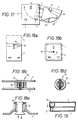
- Figs. 16a and 16b show a relevant adapter wherein the lower portion (2) forms a box or frame for receipt therein of the upper portion (1).
- the upper portion (1) includes plug pin receivers (5) and contacts (31) for contacting the mains pins (4, 7).
- Fig. 17 shows a relevant adapter in which the upper (1) and lower (2) portions are rotatably connected.
- the upper portion (1) carries the plug (8), plug pin receivers (5) and contacts (31); the lower portion (2) carries the mains pins (3, 4, 7).
- Figs. 18a and 18b show other examples of relevant adapters wherein the upper (1) and lower (2) portions are rotatably connected.
- a locking assembly (32) for preventing relative rotation of the upper (1) and lower (2) portions.
- the locking assembly is illustrated in figs. 18c-18e and comprises inner (33) and outer (34) cylinders and a locking clip (35).
- the locking clip (35) is movable between a locking position (as shown) and a releasing position, and is positively located in these positions by means of resilient lugs (36). Relative rotation of the inner (33) and outer (34) cylinders is permitted only when the locking clip (35) is in its releasing position.
- Fig. 19 shows a relevant adapter wherein a fuse (14) is contained in the upper portion (1) and bridges contacts (37) in the lower portion (2) upon securement of the portions together.
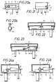
- Fig. 20a shows an adapter wherein the upper portion (1) carries a fuse (14) and the moulded plug (8).
- the lower portion (2) includes a generally w-shaped contact (40) which makes contact between the fuse (14) and plug pin (9) on securement of the two portions to each other.
- the fuse (14) and plug (8) may be carried by the lower portion (2), and a w-shaped contact (40) by the upper portion (1).
- Fig. 21 shows an adapter having a magnet (43) in the upper portion (1), and a fuse (14'), having a reed switch (42) and fuse wire (41), in the lower portion (2). Electrical contact is completed by bringing the magnet (43) close to the reed switch (42) which closes the reed switch (42).
- Fig. 22 shows a relevant adapter wherein a track (10) joining a mains pin (4) to a plug pin receiver (5) is broken and provided with contacts (45) and insulation (46). This arrangement is located in the lower portion (2). In the upper portion (1) is located a pin (44) which moves one contact (45) so as to touch the other upon securement of the upper (1) to the lower (2) portion. As can be seen, much of this circuitry can be enclosed.
- Fig. 23 shows an arrangement equivalent to that of fig. 22 except that it includes a fuse (14) in the broken track (10).
- Figs. 24a and 24b show relevant adapters wherein the upper (1) and lower (2) portions are slidably connected to one another.
- Each upper portion is provided at its forward end with a wedge (146) which, in the case of fig. 24a, raises a plug pin receiver (5) into contact with a plug pin (9) or, in the case of fig. 24b, raises a contact (47) on a track (10) leading from a mains pin (7) so as to touch a contact (47) on a plug pin receiver (5).
- a wedge 146
- Figs. 25a, 25b and 25c show embodiments of a relevant adapter.
- Fig. 25a shows upper (1) and lower (2) portions, the upper portion (1) having a recess (52) with a pin (50) mounted therein and biassed outwardly by means of a spring (51).
- the pin engages with a hole in the lower portion (2), but may be disengaged therefrom against the bias of the spring (51) to permit release of the two portions (1; 2), for example by sliding or rotation, etc.
- Fig. 25b shows a pin (50) mounted in a recess (53) in the lower portion (2) and extending therethrough.
- the pin is biassed into engagement with a hole in the upper portion (1) by means of a spring (51), but may be withdrawn therefrom against the bias to permit separation of the portions (1, 2).
- Fig. 25c shows a lower portion (2) having a cam (54) biassed into a locking position by means of a spring (51) and rotatable against the bias to release an upper portion (not shown) from the lower (2).
- Fig. 26 shows an adapter having a bolt (60) withdrawable from the lower surface of the lower portion (2) and including an enlarged head (62) to prevent its complete withdrawal.
- the upper portion (1) has a recess (61) alignable with the enlarged head (62) of the bolt (60) only when the upper (1) and lower (2) portions are in a closed position.
- Figs. 27a and 27b show lower portions (2) of relevant adapters provided with levers (63).
- the pivoted end of the lever has a pinion (64) for co-operation with a rack (65) on the upper portion (1);
- that end of the lever is provided with a cam (66) for co-operation with a recess (67).
- the lever can only be returned to a position flush with the lower surface of the lower portion (2) when the upper (1) and lower (2) portions are in a closed position, and therefore prevents insertion of the adapter into a socket when the upper and lower portions are in an open position.
- Fig. 28a shows a relevant adapter in which the earth mains pin (3) must be rotated by 90° to allow the upper and lower portions to be separated. Once the pin is rotated, a cam (68) becomes aligned with a groove (69), allowing the two portions to slide relative to one another.
- the pin may be rotated by angles other than 90°, e.g. 80° or 100° etc.
- Fig 28b shows a relevant adapter incorporating a retractable pin (4) having a shaped head (4') for contacting a moulded plug (8).
- a relevant adapter incorporating a retractable pin (4) having a shaped head (4') for contacting a moulded plug (8).
- Fig. 29 shows an adapter in which the upper (1) and lower (2) portions are slidingly connected and in which the lower portion (2) carries two mains pins (4, 7), and the upper portion (1) carries another (3).
- Fig. 36 shows a longitudinal section through a relevant adapter during insertion of a moulded plug (8) which is not shown in section.
- the particular embodiment shown includes a lower portion (2), to which is attached an upper portion (1) at a hinge (96).
- the lower portion carries the usual mains pins (3, 4) and includes an access aperture (90, 92).
- the access aperture consists essentially of two parts: a first part (90) in the lower surface of the lower portion (2) through which the body of the moulded plug (8) is inserted; and a second part (92) in the rear wall of the lower portion (2) through which the moulded plug cable passes once the plug is secured within the adapter.
- a shoulder (94) on the rear of the plug is retained against the surround of the second part (92) of the access aperture to help secure the plug in position.
- the second part of the access aperture is perfectly possible for the second part of the access aperture to be large enough to accommodate the rear of the tail portion of the moulded plug, the shape of the plug preventing it from moving out any further.
- the first part of the access aperture extends to the rear wall of the lower portion, so long as the aperture is closed at its upper extremity by a bridge of material to prevent the moulded plug from being inserted from above.
- the adapter of fig. 36, with a plug retained therein is shown from below in fig. 37.
- the access hole is somewhat larger than the moulded plug since the plug must be inserted at an angle.
- Figs. 31a and 31b show relevant adapters wherein the upper portions (1) are provided with handles (70).
- Fig. 35 shows an adapter provided with an internal flap (82) biassed into an inwardly swung, closed position (as shown) to prevent foreign objects being inserted.
- the flap is movable to an outwardly swung, open position only upon separation of the upper (1) and lower (2) portions.
Landscapes
- Details Of Connecting Devices For Male And Female Coupling (AREA)
- Connector Housings Or Holding Contact Members (AREA)
- Coupling Device And Connection With Printed Circuit (AREA)
Claims (42)
- Adapter, der in der Lage ist, einen im Formverfahren hergestellten oder anderen Stecker (8) in sich selbst zu halten, welcher Adapter folgende Teile aufweist:einen oberen Abschnitt (1) und einen unteren Abschnitt (2), welche gemeinsam eine isolierte Hülle für den Adapter bilden;eine Mehrzahl an Netzstiften (3, 4, 7), die sich unter den unteren Abschnitt (2) erstrecken, um den Adapter am Netz anzuschließen;Mittel zum Festlegen des im Formverfahren hergestellten Steckers (8) innerhalb des Adapters, wobei der im Formverfahren hergestellte Stecker (8) über mindestens zwei Stifte (9, 19) verfügt;Mittel zur Herstellung eines elektrischen Kontaktes zwischen den jeweiligen Steckerstiften (9, 19) und den Netzstiften (3, 4, 7); undMittel zur bewegbaren Festlegung des oberen Abschnittes (1) am unteren Abschnitt (2);dadurch gekennzeichnet, daß der obere und der untere Abschnitt (1, 2) zwischen einer geschlossenen Position, in welcher der Adapter mit einem Netzstecker kompatibel ist und in diesen eingesteckt werden kann; und
einer offenen Position, in welcher der Adapter mit einem Netzstecker nicht kompatibel ist und nicht in diesen eingesteckt werden kann, bewegbar sind. - Adapter nach Anspruch 1, bei welchem ein Netzstift (3), vorzugsweise der Massestift (3), eine Freigabemittel (68, 69) bildet, das zwischen einer ersten, verriegelnden, mit der Steckdose kompatiblen Position, und einer zweiten, freigebenden, mit der Steckdose nicht kompatiblen Position bewegbar ist.
- Adapter nach Anspruch 1, bei welchem ein Netzstift (4) innerhalb des Adapters zurückziehbar ist und einen inneren Kopfabschnitt (4') zur Kontaktherstellung mit dem im Formverfahren hergestellten Stecker (8) umfaßt.
- Adapter nach Anspruch 1, bei welchem der obere Abschnitt (1) des Adapters mindestens einen der Netzstifte (3) und der untere Abschnitt (2) die übrigen Netzstifte (4, 7) trägt.
- Adapter nach Anspruch 4, in welchem der obere Abschnitt (1) den Massestift (3) trägt und der untere Abschnitt (2) die übrigen Stifte (4, 7) trägt.
- Adapter nach Anspruch 1, bei welchem , wenn sich der obere und der untere Abschnitt (1, 2) in der offenen Position befinden, mindestens ein Teil des oberen Abschnittes (1) unter die untere Oberfläche des unteren Abschnittes (2) vorsteht.
- Adapter nach Anspruch 6, bei welchem der obere und der untere Abschnitt (1, 2) mit Hilfe von gekrümmten Schiebeoberflächen verschiebbar miteinander verbunden sind, wie zum Beispiel durch eine gekrümmte Rille in einem Abschnitt, welche mit einer gekrümmten Rippe oder Wulst am anderen Abschnitt kooperiert.
- Adapter nach Anspruch 1, bei welchem die Mittel zum Festlegen eines im Formverfahren hergestellten Steckers (8) innerhalb des Adapters Haltemittel umfaßt, die geeignet sind, mit Entlastungsorganen (21, 18, 17, 22) des im Formverfahren hergestellten Steckers (8) zu kooperieren.
- Adapter nach Anspruch 8, bei welchem die Haltemittel eine eingeformte Aussparung (15) entweder im oberen (1) oder im unteren (2) Abschnitt des Adapters aufweist.
- Adapter nach Anspruch 9, bei welchem die Materialmasse, vorzugsweise Kunststoffmaterial, in welcher die Aussparung (15) ausgebildet wird, gerippt (23) ist, oder eine Mehrzahl an vorspringenden Stiften aufweist, wobei die Kanten der Rippen (23) oder die Enden der Stifte die Umrisse der Aussparung (15) bestimmen.
- Adapter nach einem der Ansprüche 8-10, in welchem die Entlastungsorgane Vorsprünge oder Einzahnungen in einem Schulterabschnitt (18, 17), einem Körperabschnitt, einem Stift oder Stiften oder einem hinteren Abschnitt des im Formverfahren hergestellten Steckers umfassen und die Haltemittel entsprechende Einzahnungen oder Vorsprünge umfaßt.
- Adapter nach Anspruch 8, in welchem die Haltemittel eine Einrichtung umfaßt, die geeignet ist, mindestens einen Stift (9, 19) des im Formverfahren hergestellten Steckers (8) aufzunehmen und festzulegen.
- Adapter nach Anspruch 12, bei welchem die Haltemittel ein Loch oder eine Rille in bzw. eine Kante an einer inneren Wand des Steckers (8) umfaßt.
- Adapter nach einem der Ansprüche 8 bis 13, bei welchem die Haltemittel ein Ausgangsloch (28) oder einen Schlitz entweder im oberen (1) oder im unteren (2) Abschnitt des Adapters umfaßt, das bzw. der groß genug ist, um den Durchgang des Kabels zu ermöglichen, an dem der im Formverfahren hergestellte Stecker (8) befestigt ist, aber nicht groß genug ist, um irgendeinen Teil des im Formverfahren hergestellten Steckers (8) aufzunehmen.
- Adapter nach Anspruch 8, bei welchem die Haltemittel einen Schlüssel (29) umfaßt, der zum Beispiel durch Drehung in einer Aussparung (30) in dem im Formverfahren hergestellten Stecker (8) verriegelbar ist.
- Adapter nach Anspruch 15, bei welchem ein Betätigungsmittel zum Einrücken und Ausrücken des Schlüssels (29) an der Unterseite des unteren Abschnittes (2) des Adapters vorgesehen ist.
- Adapter nach Anspruch 1, bei welchem die Mittel zum Festlegen eines im Formverfahren hergestellten Steckers (8) innerhalb des Adapters dergestalt ist, daß ein im Formverfahren hergestellter Stecker (8) einsetzbar ist, wenn der obere (1) und der untere (2) Abschnitt aneinander befestigt sind, aber nur entfernt werden kann, wenn der obere und der untere Abschnitt (1, 2) voneinander getrennt sind.
- Adapter nach Anspruch 17, in welchem die Mittel zum Festlegen eines im Formverfahren hergestellten Steckers (8) eine oder mehrere nach innen gerichtete Öffnungsklappen (31, 32) im oberen und unteren Abschnitt (1, 2) umfaßt, welche zwischen einer geschlossenen und einer nach innen geöffneten Position beweglich sind.
- Adapter nach Anspruch 18, in welchem die Klappe oder die Klappen (31, 32) zur geschlossenen Position hin vorgespannt sind, und zwar zum Beispiel durch eine Feder oder durch Federn.
- Adapter nach Anspruch 1, bei welchem die Mittel für die Herstellung des elektrischen Kontakts zwischen den jeweiligen Steckerstiften (9, 19) und den Netzstiften (4, 7) Kontaktmittel (31) umfassen, wodurch ein derartiger Kontakt bei Festlegung des oberen Abschnittes (1) des Adapters am unteren Abschnitt (2) herstellbar ist.
- Adapter nach Anspruch 20, bei welchem die Kontaktmittel (31) erste Kontaktmittel (5) im oberen Abschnitt (1) zur Aufnahme der Steckerstifte (9, 19) im elektrischen Kontakt und zweite Kontaktmittel im unteren Abschnitt (2) zur Herstellung des elektrischen Kontakts zwischen den ersten Kontaktmitteln (5) und den Netzstiften (4, 7) beim Festlegen des oberen Abschnittes (1) des Adapters am unteren Abschnitt (2) umfaßt.
- Adapter nach Anspruch 20, bei welchem die Kontaktmittel Organe zum Halten einer Sicherung (14) oder eines Leiters im oberen Abschnitt (1) des Adapters und ein Kontaktpaar (40) im unteren Abschnitt (2) umfaßt, wobei die Sicherung (14) oder der Leiter das Kontaktpaar (40) bei Festlegung des oberen (1) Abschnittes am unteren (2) Abschnitt überbrücken.
- Adapter nach Anspruch 20, bei welchem die Kontaktmittel einen Schalter (42), vorzugsweise im stromführenden Stiftkreis, im unteren Abschnitt (2) des Adapters umfaßt, der in eine offene Position vorgespannt ist, aber bei Befestigung des oberen Abschnittes (1) am unteren (2) durch Schließorgane (43) am oberen Abschnitt (1) geschlossen ist.
- Adapter nach Anspruch 21, bei welchem der Schalter einen Zungenschalter (42) und die Schließvorrichtung einen Magnet (43) zum Schließen des Zungenschalters (42) bei Festlegung des oberen (1) Abschnittes am unteren (2) Abschnitt aufweist.
- Adapter nach Anspruch 21, bei welchem der Schalter ein Paar von Kontakten (45) aufweist, die sich nebeneinander befinden, aber im Sinne einer voneinander weggerichteten Bewegung vorgespannt sind, und wobei die Schließorgane einen vorspringenden Keil oder Stift (44) umfaßt, der geeignet ist, einen Kontakt (45) so zu bewegen, daß er den anderen berührt.
- Adapter nach Anspruch 1, derart daß der Adapter und der darin festgelegte Stecker (8) nicht voneinander getrennt werden können, wenn der Adapter in eine Steckdose eingesteckt ist.
- Adapter nach Anspruch 24, derart daß sich während des Einsetzens des im Formverfahren hergestellten Steckers (8) mindestens ein Abschnitt des im Formverfahren hergestellten Steckers (8) unter eine untere Oberfläche des unteren Abschnittes (2) erstreckt.
- Adapter nach Anspruch 21, bei welchem zumindest die untere Oberfläche des unteren Abschnittes (2) mit einer Zugangsöffnung (90, 92) versehen ist, durch welche der im Formverfahren hergestellte Stecker (8) eingesetzt oder entfernt werden kann.
- Adapter nach Anspruch 26, bei welchem die Mittel zur Festlegung eines im Formverfahren hergestellten Steckers (8) innerhalb des Adapters Haltemittel umfaßt, die geeignet ist, mit Entlastungsorganen des im Formverfahren hergestellten Steckers (8) zu kooperieren.
- Adapter nach Anspruch 29, bei welchem die Haltemittel Mittel umfassen, die geeignet sind, mindestens einen Stift (9, 19) des im Formverfahren hergestellten Steckers (8) aufzunehmen und festzulegen.
- Adapter nach Anspruch 1, derart, daß der obere und der untere Abschnitt (1, 2) nicht voneinander getrennt werden können, solange der Adapter in einer Steckdose eingesteckt ist.
- Adapter nach Anspruch 31, welche Freigabemittel aufweist, die sich an der unteren Oberfläche des unteren Abschnittes (2) des Adapters befinden und so betätigbar sind, daß die Freigabe des oberen Abschnittes (1) vom unteren Abschnitt (2) ermöglicht wird.
- Adapter nach Anspruch 32, bei welchem der obere und der untere Abschnitt (1, 2) verschiebbar oder drehbar aneinander befestigt sind und die Freigabemittel einen Stift (50) umfassen, der sich in einem Abschnitt befindet und im Sinne des Eingriffs mit einem Loch oder einer Aussparung (52) im anderen Abschnitt vorgespannt ist, wobei der Stift (50) aus dem Eingriff mit dem Loch oder der Aussparung (52) heraus bewegbar ist.
- Adapter nach Anspruch 32, bei welchem der obere und der untere Abschnitt (1, 2) verschiebbar oder drehbar aneinander befestigt sind, und die Freigabemittel einen Nocken (54) umfaßt, der. zur Lösung des oberen Abschnittes vom unteren Abschnitt (1, 2) des Adapters drehbar ist
- Adapter nach Anspruch 32, bei welchem der obere und der untere Abschnitt (1, 2) auf schwenkbare, verschiebbare, drehbare oder andere bewegliche Weise aneinander befestigt und zwischen einer geschlossenen und einer offenen Position beweglich sind, und die Freigabemittel zwischen einer ersten, verriegelnden Position und einer zweiten, freigebenden Position beweglich ist, wobei sie unter der unteren Oberfläche des unteren Abschnittes (2) vorstehen und in der Lage sind, die verriegelnde Position nur dann einzunehmen, wenn sich der obere und der untere Abschnitt (1, 2) in der geschlossenen Position befinden.
- Adapter nach Anspruch 35, bei welchem die Freigabevorrichtung einen Stift, eine Schraube oder ähnliches (60) umfaßt, welcher von der unteren Oberfläche des unteren Abschnittes (2) entfernbar ist, aber eine Sicherung (62) umfaßt, um zu verhindern, daß er vollständig entfernt werden kann, und der obere Abschnitt (1) mit einer Aussparung (61) ausgestattet ist, um den Stift, die Schraube oder ähnliches (60) aufzunehmen, wobei die Aussparung (61) nur dann mit dem Stift, der Schraube oder ähnlichem (60) ausgerichtet ist, wenn sich der obere und der untere Abschnitt (1, 2) in der geschlossenen Position befinden.
- Adapter nach Anspruch 35, bei welchem die Freigabeorgane einen Hebel (63) umfassen, der am unteren Abschnitt (2) angebracht ist und schwenkbar zwischen einer Verriegelungsposition, die bündig mit der unteren Oberfläche des unteren Abschnittes (2) ist, und einer Freigabeposition ist.
- Adapter nach einem der vorhergehenden Ansprüche, in welchem die obere Position mit einem Griff versehen ist.
- Adapter nach einem der vorhergehenden Ansprüche, in welchem die Netzstifte (3, 4, 7) und die Mittel zur Herstellung des elektrischen Kontaktes zwischen den Netzstiften (3, 4, 7) und den Steckerstiften (9, 19) einstückig aus gestanztem Kupferblech oder einem anderen leitenden Blechmaterial hergestellt sind.
- Adapter nach einem der vorhergehenden Ansprüche, bei welchem mindestens einer der Netzstifte (3, 4, 7) an einem Steckerstiftaufnehmer durch eine Metallschiene angeschlossen ist, welche mindestens eine teilweise Verdrehung aufweist, um eine relative Bewegung der Steckerstifte (9, 19) und der Netzstifte (3, 4, 7) zu ermöglichen.
- Adapter nach einem der vorhergehenden Ansprüche, bei welchem der obere und der untere Abschnitt (1, 2) zwischen einer geschlossenen und einer offenen Position bewegbar sind und, zum Beispiel durch eine Feder, zur geschlossenen Position hin vorgespannt sind.
- Adapter nach einem der vorhergehenden Ansprüche, der mit einem inneren Element versehen ist, das zwischen einer nach innen geschwungenen, geschlossenen Position und einer nach außen geschwungenen, offenen Position bewegbar ist und die Öffnung abdeckt, durch welche der im Formverfahren hergestellte Stecker (8) oder seine Kabel hindurchtreten.
Applications Claiming Priority (3)
| Application Number | Priority Date | Filing Date | Title |
|---|---|---|---|
| GB9011898 | 1990-05-29 | ||
| GB909011898A GB9011898D0 (en) | 1990-05-29 | 1990-05-29 | Improvements in adapters for electrical plugs |
| PCT/GB1991/000849 WO1991019335A1 (en) | 1990-05-29 | 1991-05-29 | Improvements in adapters for electrical plugs |
Publications (2)
| Publication Number | Publication Date |
|---|---|
| EP0531383A1 EP0531383A1 (de) | 1993-03-17 |
| EP0531383B1 true EP0531383B1 (de) | 1997-05-14 |
Family
ID=10676686
Family Applications (1)
| Application Number | Title | Priority Date | Filing Date |
|---|---|---|---|
| EP91910111A Expired - Lifetime EP0531383B1 (de) | 1990-05-29 | 1991-05-29 | Verbesserungen an adaptern für elektrische stecker |
Country Status (10)
| Country | Link |
|---|---|
| EP (1) | EP0531383B1 (de) |
| AT (1) | ATE153183T1 (de) |
| AU (1) | AU656139B2 (de) |
| DE (1) | DE69126133T2 (de) |
| DK (1) | DK0531383T3 (de) |
| ES (1) | ES2103813T3 (de) |
| GB (1) | GB9011898D0 (de) |
| GR (1) | GR3023416T3 (de) |
| WO (1) | WO1991019335A1 (de) |
| ZA (1) | ZA914090B (de) |
Families Citing this family (6)
| Publication number | Priority date | Publication date | Assignee | Title |
|---|---|---|---|---|
| GB2320982B (en) * | 1996-05-24 | 2001-07-18 | Board Tech Electric Co Ltd | Adapter with interchangeable plug board |
| GB2355865B (en) * | 1999-10-28 | 2001-12-19 | Innovative Power Solutions Ltd | Electrical connecting device |
| GB2399461A (en) * | 2003-03-11 | 2004-09-15 | Sandal Plc | A lockable electrical adapter |
| DE10316528A1 (de) * | 2003-04-10 | 2004-10-21 | Martin Kaiser Gmbh & Co. Kg Elektrotechnische Fabrik | Steckeradapter, insbesondere zum Anschluss von Lampen |
| EP1854183A1 (de) * | 2005-02-09 | 2007-11-14 | Sandal Plc | Elektrischer steckeradapter |
| GB2432465A (en) * | 2005-11-16 | 2007-05-23 | Ep Ind Ltd | Adaptor providing support for electrical plug |
Family Cites Families (4)
| Publication number | Priority date | Publication date | Assignee | Title |
|---|---|---|---|---|
| FR2209230B1 (de) * | 1972-12-05 | 1976-06-04 | Bunker Ramo | |
| DE8009606U1 (de) * | 1980-04-08 | 1980-08-07 | Braun Ag, 6000 Frankfurt | Netz-Steckvorrichtung für elektrische Geräte |
| DE3274038D1 (en) * | 1982-08-04 | 1986-12-04 | Corabelment Ag | Multiple pin electrical plug |
| GB8811664D0 (en) * | 1988-05-17 | 1988-06-22 | Hossack S | Adapters for electrical plugs |
-
1990
- 1990-05-29 GB GB909011898A patent/GB9011898D0/en active Pending
-
1991
- 1991-05-29 DE DE69126133T patent/DE69126133T2/de not_active Expired - Fee Related
- 1991-05-29 AU AU79045/91A patent/AU656139B2/en not_active Ceased
- 1991-05-29 ES ES91910111T patent/ES2103813T3/es not_active Expired - Lifetime
- 1991-05-29 AT AT91910111T patent/ATE153183T1/de not_active IP Right Cessation
- 1991-05-29 ZA ZA914090A patent/ZA914090B/xx unknown
- 1991-05-29 EP EP91910111A patent/EP0531383B1/de not_active Expired - Lifetime
- 1991-05-29 DK DK91910111.3T patent/DK0531383T3/da active
- 1991-05-29 WO PCT/GB1991/000849 patent/WO1991019335A1/en not_active Ceased
-
1997
- 1997-05-15 GR GR970400883T patent/GR3023416T3/el unknown
Also Published As
| Publication number | Publication date |
|---|---|
| GB9011898D0 (en) | 1990-07-18 |
| DE69126133T2 (de) | 1997-12-11 |
| DK0531383T3 (da) | 1997-12-01 |
| DE69126133D1 (de) | 1997-06-19 |
| ZA914090B (en) | 1993-01-27 |
| HK1001577A1 (en) | 1998-06-26 |
| AU656139B2 (en) | 1995-01-27 |
| EP0531383A1 (de) | 1993-03-17 |
| ES2103813T3 (es) | 1997-10-01 |
| AU7904591A (en) | 1991-12-31 |
| ATE153183T1 (de) | 1997-05-15 |
| WO1991019335A1 (en) | 1991-12-12 |
| GR3023416T3 (en) | 1997-08-29 |
Similar Documents
| Publication | Publication Date | Title |
|---|---|---|
| JP3338552B2 (ja) | 電気コネクタ、特に充電用コネクタ | |
| EP0959532B1 (de) | Steckverbinder mit Verriegelungshebel | |
| JP2842145B2 (ja) | コネクタ | |
| JP2762347B2 (ja) | 端子位置保証手段を有するフード付き電気コネクタ | |
| JP2634524B2 (ja) | 暗電流ヒューズの断続機構 | |
| JP2501005Y2 (ja) | コネクタ | |
| US7488195B2 (en) | Transparent insulating enclosure | |
| US5947572A (en) | Hard disk drive drawer | |
| JPH03504548A (ja) | バッテリーハウジング | |
| US5406449A (en) | Pullout type electric disconnect switch | |
| US5816825A (en) | Connector unit provided with magnetically locking mechanism | |
| US4810204A (en) | Battery pack connection | |
| US4932886A (en) | Shockproof electrical outlet | |
| KR100327895B1 (ko) | 하니스커넥터 | |
| US5897402A (en) | Releasable locking connector | |
| AU656139B2 (en) | Improvements in adapters for electrical plugs | |
| EP0898331B1 (de) | Elektrischer Steckverbinder | |
| US6512177B2 (en) | Protection cover for a battery terminal and a battery terminal | |
| US6459354B2 (en) | Breaker apparatus | |
| GB2202096A (en) | 13amp 3 pin electrical connector | |
| US5971789A (en) | Locking angular electrical connecting plug with rotatable release handle | |
| HK1001577B (en) | Improvements in adapters for electrical plugs | |
| GB2381669A (en) | Folding plug | |
| JPH1092535A (ja) | サービスプラグのレバー保持機構 | |
| JPH051175U (ja) | コネクタ |
Legal Events
| Date | Code | Title | Description |
|---|---|---|---|
| PUAI | Public reference made under article 153(3) epc to a published international application that has entered the european phase |
Free format text: ORIGINAL CODE: 0009012 |
|
| 17P | Request for examination filed |
Effective date: 19921229 |
|
| AK | Designated contracting states |
Kind code of ref document: A1 Designated state(s): AT BE CH DE DK ES FR GB GR IT LI LU NL SE |
|
| 17Q | First examination report despatched |
Effective date: 19940607 |
|
| GRAG | Despatch of communication of intention to grant |
Free format text: ORIGINAL CODE: EPIDOS AGRA |
|
| GRAH | Despatch of communication of intention to grant a patent |
Free format text: ORIGINAL CODE: EPIDOS IGRA |
|
| GRAH | Despatch of communication of intention to grant a patent |
Free format text: ORIGINAL CODE: EPIDOS IGRA |
|
| GRAA | (expected) grant |
Free format text: ORIGINAL CODE: 0009210 |
|
| AK | Designated contracting states |
Kind code of ref document: B1 Designated state(s): AT BE CH DE DK ES FR GB GR IT LI LU NL SE |
|
| REF | Corresponds to: |
Ref document number: 153183 Country of ref document: AT Date of ref document: 19970515 Kind code of ref document: T |
|
| REG | Reference to a national code |
Ref country code: CH Ref legal event code: NV Representative=s name: PATENTANWAELTE SCHAAD, BALASS, MENZL & PARTNER AG Ref country code: CH Ref legal event code: EP |
|
| ITF | It: translation for a ep patent filed | ||
| REF | Corresponds to: |
Ref document number: 69126133 Country of ref document: DE Date of ref document: 19970619 |
|
| ET | Fr: translation filed | ||
| REG | Reference to a national code |
Ref country code: GR Ref legal event code: FG4A Free format text: 3023416 |
|
| REG | Reference to a national code |
Ref country code: ES Ref legal event code: FG2A Ref document number: 2103813 Country of ref document: ES Kind code of ref document: T3 |
|
| REG | Reference to a national code |
Ref country code: DK Ref legal event code: T3 |
|
| PLBE | No opposition filed within time limit |
Free format text: ORIGINAL CODE: 0009261 |
|
| STAA | Information on the status of an ep patent application or granted ep patent |
Free format text: STATUS: NO OPPOSITION FILED WITHIN TIME LIMIT |
|
| 26N | No opposition filed | ||
| REG | Reference to a national code |
Ref country code: GB Ref legal event code: 732E |
|
| REG | Reference to a national code |
Ref country code: GB Ref legal event code: IF02 |
|
| PGFP | Annual fee paid to national office [announced via postgrant information from national office to epo] |
Ref country code: DK Payment date: 20080515 Year of fee payment: 18 Ref country code: LU Payment date: 20080604 Year of fee payment: 18 |
|
| PGFP | Annual fee paid to national office [announced via postgrant information from national office to epo] |
Ref country code: AT Payment date: 20080514 Year of fee payment: 18 |
|
| PGFP | Annual fee paid to national office [announced via postgrant information from national office to epo] |
Ref country code: SE Payment date: 20080509 Year of fee payment: 18 |
|
| PGFP | Annual fee paid to national office [announced via postgrant information from national office to epo] |
Ref country code: GR Payment date: 20080410 Year of fee payment: 18 |
|
| PGFP | Annual fee paid to national office [announced via postgrant information from national office to epo] |
Ref country code: ES Payment date: 20090605 Year of fee payment: 19 Ref country code: NL Payment date: 20090504 Year of fee payment: 19 |
|
| PGFP | Annual fee paid to national office [announced via postgrant information from national office to epo] |
Ref country code: FR Payment date: 20090515 Year of fee payment: 19 Ref country code: IT Payment date: 20090516 Year of fee payment: 19 Ref country code: DE Payment date: 20090527 Year of fee payment: 19 |
|
| PGFP | Annual fee paid to national office [announced via postgrant information from national office to epo] |
Ref country code: BE Payment date: 20090525 Year of fee payment: 19 |
|
| PGFP | Annual fee paid to national office [announced via postgrant information from national office to epo] |
Ref country code: CH Payment date: 20090513 Year of fee payment: 19 |
|
| REG | Reference to a national code |
Ref country code: DK Ref legal event code: EBP |
|
| PG25 | Lapsed in a contracting state [announced via postgrant information from national office to epo] |
Ref country code: AT Free format text: LAPSE BECAUSE OF NON-PAYMENT OF DUE FEES Effective date: 20090529 |
|
| PG25 | Lapsed in a contracting state [announced via postgrant information from national office to epo] |
Ref country code: DK Free format text: LAPSE BECAUSE OF NON-PAYMENT OF DUE FEES Effective date: 20090531 |
|
| PG25 | Lapsed in a contracting state [announced via postgrant information from national office to epo] |
Ref country code: GR Free format text: LAPSE BECAUSE OF NON-PAYMENT OF DUE FEES Effective date: 20091202 |
|
| PGFP | Annual fee paid to national office [announced via postgrant information from national office to epo] |
Ref country code: GB Payment date: 20100329 Year of fee payment: 20 |
|
| BERE | Be: lapsed |
Owner name: *HOSSACK SIMON Effective date: 20100531 |
|
| REG | Reference to a national code |
Ref country code: NL Ref legal event code: V1 Effective date: 20101201 |
|
| REG | Reference to a national code |
Ref country code: CH Ref legal event code: PL |
|
| REG | Reference to a national code |
Ref country code: FR Ref legal event code: ST Effective date: 20110131 |
|
| PG25 | Lapsed in a contracting state [announced via postgrant information from national office to epo] |
Ref country code: LI Free format text: LAPSE BECAUSE OF NON-PAYMENT OF DUE FEES Effective date: 20100531 Ref country code: CH Free format text: LAPSE BECAUSE OF NON-PAYMENT OF DUE FEES Effective date: 20100531 |
|
| PG25 | Lapsed in a contracting state [announced via postgrant information from national office to epo] |
Ref country code: BE Free format text: LAPSE BECAUSE OF NON-PAYMENT OF DUE FEES Effective date: 20100531 Ref country code: IT Free format text: LAPSE BECAUSE OF NON-PAYMENT OF DUE FEES Effective date: 20100529 Ref country code: NL Free format text: LAPSE BECAUSE OF NON-PAYMENT OF DUE FEES Effective date: 20101201 |
|
| PG25 | Lapsed in a contracting state [announced via postgrant information from national office to epo] |
Ref country code: DE Free format text: LAPSE BECAUSE OF NON-PAYMENT OF DUE FEES Effective date: 20101201 Ref country code: LU Free format text: LAPSE BECAUSE OF NON-PAYMENT OF DUE FEES Effective date: 20090529 |
|
| PG25 | Lapsed in a contracting state [announced via postgrant information from national office to epo] |
Ref country code: SE Free format text: LAPSE BECAUSE OF NON-PAYMENT OF DUE FEES Effective date: 20090530 Ref country code: FR Free format text: LAPSE BECAUSE OF NON-PAYMENT OF DUE FEES Effective date: 20100531 |
|
| REG | Reference to a national code |
Ref country code: GB Ref legal event code: PE20 Expiry date: 20110528 |
|
| REG | Reference to a national code |
Ref country code: ES Ref legal event code: FD2A Effective date: 20110708 |
|
| PG25 | Lapsed in a contracting state [announced via postgrant information from national office to epo] |
Ref country code: ES Free format text: LAPSE BECAUSE OF NON-PAYMENT OF DUE FEES Effective date: 20110628 |
|
| PG25 | Lapsed in a contracting state [announced via postgrant information from national office to epo] |
Ref country code: GB Free format text: LAPSE BECAUSE OF EXPIRATION OF PROTECTION Effective date: 20110528 |
|
| PG25 | Lapsed in a contracting state [announced via postgrant information from national office to epo] |
Ref country code: ES Free format text: LAPSE BECAUSE OF NON-PAYMENT OF DUE FEES Effective date: 20100530 |