EP0530384B1 - Machine tool control for concurrent machining of sheet material with a plurality of tools - Google Patents
Machine tool control for concurrent machining of sheet material with a plurality of tools Download PDFInfo
- Publication number
- EP0530384B1 EP0530384B1 EP19910113358 EP91113358A EP0530384B1 EP 0530384 B1 EP0530384 B1 EP 0530384B1 EP 19910113358 EP19910113358 EP 19910113358 EP 91113358 A EP91113358 A EP 91113358A EP 0530384 B1 EP0530384 B1 EP 0530384B1
- Authority
- EP
- European Patent Office
- Prior art keywords
- tool
- carrier
- point
- spindle
- control
- Prior art date
- Legal status (The legal status is an assumption and is not a legal conclusion. Google has not performed a legal analysis and makes no representation as to the accuracy of the status listed.)
- Expired - Lifetime
Links
Images

Classifications
-
- G—PHYSICS
- G05—CONTROLLING; REGULATING
- G05B—CONTROL OR REGULATING SYSTEMS IN GENERAL; FUNCTIONAL ELEMENTS OF SUCH SYSTEMS; MONITORING OR TESTING ARRANGEMENTS FOR SUCH SYSTEMS OR ELEMENTS
- G05B19/00—Programme-control systems
- G05B19/02—Programme-control systems electric
- G05B19/18—Numerical control [NC], i.e. automatically operating machines, in particular machine tools, e.g. in a manufacturing environment, so as to execute positioning, movement or co-ordinated operations by means of programme data in numerical form
- G05B19/408—Numerical control [NC], i.e. automatically operating machines, in particular machine tools, e.g. in a manufacturing environment, so as to execute positioning, movement or co-ordinated operations by means of programme data in numerical form characterised by data handling or data format, e.g. reading, buffering or conversion of data
- G05B19/4086—Coordinate conversions; Other special calculations
Definitions
- So-called multiple processing machines are used in the production of plate-shaped workpieces.
- machining technologies are integrated in this machine type, e.g. Drilling, milling, grooving, edge banding.
- all the tools available on the multiple processing machines such as drills, milling cutters, grooving saws, are common attached to a mobile tool carrier. To position a tool at a working position, the entire tool carrier is moved in the plane above the plate-shaped workpiece so that the tool with which a machining operation is to be carried out is located above the machining point.
- the machine tool control must know the position of the respective tool or the respective tool spindle with respect to the tool carrier zero point. Each time a tool selected for machining is specified, the machine tool control must then take into account the position of the machining tool with respect to the tool carrier zero point and move the tool carrier accordingly.
- Drills of the numerical control can be specified individually, so that one command is required for each drill used.
- the first-mentioned document refers to a machine tool controller for machining turned parts, in which only one tool is used to machine a workpiece .
- a symmetrical machining of a workpiece is also known from the latter of the two cited documents, each with its own tool successively machining the workpiece at points symmetrically arranged with respect to one another.
- a mirror-image arrangement of several tools which simultaneously use different tools, for example drills, on a common tool module cannot be derived from this.
- the object of the invention is to obtain a machine tool control with which simple tool module machining is possible.
- a machine tool control for processing plate-shaped workpieces, in particular made of wood or plastic, with a numerical and a programmable control part for controlling the position and the functions of a tool holder in a tool holder coordinate system, with at least one processing unit on the tool holder with at least two using a Gear-driven tool spindles are attached, the tool carrier being assigned a tool carrier reference point and each processing unit an aggregate reference point and being stored in the control system, the position of the tool spindles relative to the aggregate reference points and the position of the aggregate reference points relative to the tool carrier reference point being specified and according to specifications a tool spindle and a position for this in the tool carrier coordinate system, the tool carrier is positioned by the position of a The given tool spindle with regard to the tool carrier reference point is taken into account as a position correction, any tool spindle combinations being specified as tool modules and each tool module being assigned a freely selectable leading tool spindle, with respect to which the positioning in the tool carrier coordinate system takes place.
- Any number of tool modules can be stored once in the memory locations provided for this purpose in the machine tool control system, so that they can be called up at any time for a machining operation.
- the position in the machine tool coordinate system need only be specified for this leading drill.
- the positioning of the tool holder is then carried out by the numerical control with respect to the leading tool spindle as with any other tool spindle.
- the drills involved are automatically selected by the programmable logic controller.
- each tool module can be assigned a mirror-image tool module which is activated by a mirror command.
- a mirror-image tool module which is activated by a mirror command.
- Bores for hinges and fittings can be made at the top and bottom of a plate-shaped workpiece.
- a further advantageous embodiment of the invention wherein a first and a second workpiece zero point are specified in the tool carrier coordinate system, the leading tool spindle being moved to a first point with respect to the first workpiece zero point, whereby after triggering the mirror command, the first point is mirrored with respect to the first workpiece zero point and the mirrored leading spindle is moved to a second point which corresponds to the mirrored point with respect to the second workpiece zero point.
- the machine tool control can be programmed and operated particularly easily by the manufacturer and the user using a graphical user interface in a dialog process.
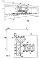
- Fig. 1 shows the schematic representation of a machine tool with a tool holder WT, which is suspended on a machine tool holder 1 movable.
- a tool carrier coordinate system X, Y, Z is assigned to the tool carrier WT, in which it can be positioned using control commands from a machine tool control, not shown.
- Drilling and milling units B are arranged on the tool carrier WT, each of which has at least one, but generally at least two tool spindles, which are generally driven by a gear assigned to each drilling unit.
- the tool spindles hold tools W, for example drills, the tips of which do not necessarily have to be arranged in one plane, as shown in FIG. 1, since tools W of different geometry, for example drills of different diameters and different lengths, can also be used.
- the tool carrier WT can be positioned over a workpiece support 2.
- Plate-shaped workpieces for example chipboard, blockboard, plastic plate, etc.
- the workpieces do not necessarily have to have a flat surface; it only has to be ensured that the tools W are each spaced from the most elevated point of a plate-shaped workpiece.
- a machining operation is to be carried out with a tool W
- this tool must be brought into the working position. For this purpose, it is moved in the axial direction to the workpiece support 2. This shift is effected - usually via the spindle - with an actuator which is controlled by a programmable logic controller. If the selected tool W is in the working position, the machining operation is carried out by an infeed movement of the tool carrier WT in the Z direction.
- the other spindles located in the drilling unit of the selected tool spindle or the selected tool W run idle when they are driven by the same gear.
- the position of the tools or the tool spindles W1 ... W21 must be known to the machine tool control so that a corresponding position correction can be carried out within the machine tool coordinate system during the positioning. This is explained below with reference to FIG. 2.
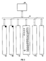
- FIG. 2 shows a tool carrier WT, to which a tool carrier zero point WTO is assigned.
- Three drilling units B1, B2, B3 are attached to the tool carrier WT.
- the drilling unit B1 has the tool spindles W1, W2, W3, the drilling unit W2 the tool spindles W4 ... W7 and the drilling unit B3 the tool spindles W8 ... W15.
- Each drilling unit B1, B2, B3 is one Drilling unit zero assigned to B10, B20, B30.
- the drilling unit zero points B10, B20, B30 are each arranged at a corner of the drilling units B1, B2, B3, since such a corner point is well suited for measuring the tool spindles W1 ... W15.
- the drilling unit zero points could, however, be easily determined at any other point in the coordinate system KW, for example at another exposed point on the tool carrier WT. This position should be selected in such a way that it is as simple as possible to measure the tool spindles W1 ... W15. The same applies to the drilling unit zero points B10, B20, B30 for the tool carrier zero point WTO.
- the position of the drilling unit zero points B10, B20, B30 with respect to the tool carrier zero point WTO is predefined for the machine tool control by vectors V1, V2, V3.
- the position of the tool spindles W1 ... W15 with respect to the drilling unit zero points B10, B20, B30 is also given to the machine tool control system by vectors, of which only the vectors V4, V5, V6 are shown in FIG. 2. Since the machine tool control positions the entire tool holder via the tool holder zero point WT in the machine tool coordinate system KW, the position of this tool spindle must be taken into account as a position correction when positioning a tool spindle W1 ... W15. This position correction can be calculated using vectors V1 ... V6, which can be specified as machine data for the machine tool control.
- This type of specification of the tool spindles W1 ... W15 for the tool carrier zero point allows a simple exchange of drilling units if the same tool carrier WT with a different drilling unit configuration or with drilling units with different spindle equipment is to be used for another type of such machine tool. If the drilling unit zero points B10, B20, B30 are not changed, the machine tool control simply has to be given the new position of tool spindles with respect to these zero points. Secondly, this type of specification of the geometric position of the tool spindles W1 ... W15 permits simple and clear execution or programming of the machine tool control. This is described with reference to FIG. 3.
- Fig. 3 shows the block diagram of a machine tool control with an operating and visualization device BV, which via a bus system B with a memory for setting data SD, a memory for machine data MD, a numerical control part NC, an interface I, a programmable logic controller PLC and an on - Output unit IO is connected.
- the geometrical data of the tools are stored in the memory for the setting data, for example the respective length of the drills fastened in the tool spindles W1 ... W15.
- the geometric position of the tool spindles W1 ... W15, the drilling unit zero points B10, B20, B30 and the tool carrier zero point WT are stored in the memory for the machine data MD.
- the travels for the tool holder are then calculated taking into account the position correction, i.e. the position of a selected tool spindle W1 ... W15 to the tool holder zero point via the respective unit zero point.
- the programmable logic controller PLC then takes over the disengagement of the tool spindles so that the tools are brought into the working position.
- Interface I is provided for the interaction between the numerical control part NC and the programmable control part PLC.
- Interface I has at least memory locations for the "logic zero" and “logic one” states. The number of storage locations corresponds to the number of tool spindles W1 ... W21.
- the user specifies a tool spindle W1 ... W15 and the position in the tool holder coordinate system KW to which this spindle is to be brought via the operating and visualization unit BV.
- the numerical control then calculates the path of the tool holder based on the geometry information stored in the machine data memory.
- the value "logical one" is set in interface I in the memory location assigned to the selected tool spindle.
- the programmable logic controller PLC polls the states of the memory locations S1 ... S21 of the interface I cyclically and issues a control command to the disengaging device of the selected tool spindle via the IO input / output unit, in the example, the tool spindle W4. This process can be carried out by the programmable logic controller PLC at the same time as the numerical control NC is calculating the travel path or the tool carrier is already moving.
- the tool carrier WT is in a Z position relatively close to the workpiece, so that a tool to be brought into the working position would come into contact with the workpiece even before the tool carrier is in the correct position.
- the Z position must be corrected beforehand.
- the length of the tools installed in the spindles W1 ... W15 can be stored in the memory for the setting data SD.
- the numerical control NC will then first check whether the tool carrier is in a Z position, which ensures a safety distance between the tool and the workpiece when the tool spindle is disengaged, and if necessary correct this Z position before positioning in the XY direction and only then in Interface I set the corresponding bit for the tool spindle W1 ... W21.
- Tool module processing makes it possible to select several tools at the same time with just one command and to execute a machining process with them.
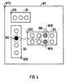
- FIG. 4 again shows the tool carrier WT with the tool carrier zero point WTO and the drilling units B1, B2, B3 and the drilling unit zero points B10, B20, B30.
- the tool spindles W5, W10, W14 are selected as drilling modules or - since they do not necessarily have to be drills - as tool modules.
- the tool spindle W5 is black and the tool spindles W10 to W14 are drawn with dashed lines.
- the tool spindle W5 is stored as a so-called leading drill in the data area SD of the machine tool control.
- the tool spindles W10 and W14 are referred to as involved drills and are also stored in the control. Leading and involved drills or tool spindles of a tool module can be freely configured by the user.
- the execution of a positioning and machining process is just as simple as the positioning of an individual tool already described.
- the user does not just specify a single tool spindle and its position, but rather specifies the corresponding tool module and the position at which the leading drill W5 of the tool module is to be positioned.
- the numerical control NC then calculates the travel path of the tool carrier WT with respect to the leading drill W5 and positions it accordingly.
- Interface I no longer only sets 1 bit for a tool spindle, but instead the associated memory locations S5, S10, S14 with the status "logical one" are set for all tool spindles W5, W10, W14 belonging to the tool module, so that the programmable logic controller PLC all involved and the leading drill of a tool module can be brought into working position.
- mirror-image hole configurations (example: fitting fittings to doors and windows etc.). Such mirror-image hole configurations can be implemented, as will be described below with reference to FIG. 5.
- FIG. 5 shows a tool carrier WT with its associated zero point WTO, which is equipped with an unspecified (rectangle) and a drilling unit B4.
- the drilling unit B4 has 6 tool spindles W16 to W21, which are arranged symmetrically to a line of symmetry SL.
- the tool spindles W16, W17, W18 are each assigned a symmetrical tool spindle W19, W20, W21.
- the tool spindles W16, W18, W19 are selected as the tool module, the tool spindle W16 being the leading tool spindle and the tool spindles W18, W19 being the tool spindles involved.
- the tool module is mirrored by triggering a mirror command by assigning the mirror-image tool spindle to each tool spindle of the tool module.
- the tool spindle W21 becomes the leading and the tool spindles W19, W18 become involved tool spindles of the mirrored tool module.
- a first workpiece zero point KW1 and a second workpiece zero point KW2 are defined in the machine tool coordinate system KW with the coordinates X, Y, Z and the zero point KW0. These workpiece zero points KW1, KW2 are each located in the corner points of a stop device which are attached to the workpiece support 2 known from FIG. 1.
- the workpiece carrier is now positioned via the machine tool control so that the leading tool spindle W16 of the tool module at the position X'1, Y'1 with respect to the Workpiece zero coordinate system X ', Y' is brought.
- the corresponding hole configuration (W19), (W18), (W16) can then be introduced into the workpiece W1 by the infeed movement of the tool carrier in the Z direction.
- the second workpiece W2 can be placed on the second workpiece stop A2.
- the tool module is automatically mirrored and the coordinates X2, Y2 with respect to the coordinate system X "2, Y" 2 are calculated for the mirrored leading tool spindle W21, where X "2 is equal to X'1 and Y''2 is equal to -Y'11.
- the tool carrier WT can then be positioned by the numerical control NC and the mirrored hole configuration (W21), (W19), (W18) corresponding to the tool module. be introduced into the workpiece W2.
Description
Bei der Fertigung plattenförmiger Werkstücke werden sogenannte Mehrfachbearbeitungsmaschinen eingesetzt. Bei diesem Maschinentyp sind mehrere Bearbeitungstechnologien integriert, z.B. Bohren, Fräsen, Nutsägen, Kantenumleimen. Im Gegensatz zu besonders aus der Metallbearbeitung bekannten Werkzeugmaschinen, bei denen gewöhnlich verschiedene Werkzeuge in einem Werkzeugrevolver oder einem anderen Werkzeugmagazin untergebracht sind und nach Bedarf aus diesen entnommen werden können, sind bei den Merfachbearbeitungsmaschinen alle verfügbaren Werkzeuge, wie Bohrer, Fräser, Nutsäge, gemeinsam auf einem fahrbaren Werkzeugträger angebracht. Zur Positionierung eines Werkzeugs an eine Arbeitsposition wird dabei der gesamte Werkzeugträger in der Ebene über dem plattenförmigen Werkstück so verfahren, daß das Werkzeug, mit dem ein Bearbeitungsvorgang durchgeführt werden soll, sich über dem Bearbeitungspunkt befindet. Dazu muß der Werkzeugmaschinensteuerung die Position des jeweiligen Werkzeugs bzw. der jeweiligen Werkzeugspindel bezüglich des Werkzeugträgernullpunktes bekannt sein. Bei jeder Vorgabe eines für die Bearbeitung ausgewählten Werkzeuges muß dann die Werkzeugmaschinensteuerung die Lage des Bearbeitungswerkzeuges bezüglich dem Werkzeugträgernullpunkt berücksichtigen und den Werkzeugträger entsprechend verfahren.So-called multiple processing machines are used in the production of plate-shaped workpieces. Several machining technologies are integrated in this machine type, e.g. Drilling, milling, grooving, edge banding. In contrast to machine tools particularly known from metalworking, in which various tools are usually accommodated in a tool turret or another tool magazine and can be removed from them as required, all the tools available on the multiple processing machines, such as drills, milling cutters, grooving saws, are common attached to a mobile tool carrier. To position a tool at a working position, the entire tool carrier is moved in the plane above the plate-shaped workpiece so that the tool with which a machining operation is to be carried out is located above the machining point. For this purpose, the machine tool control must know the position of the respective tool or the respective tool spindle with respect to the tool carrier zero point. Each time a tool selected for machining is specified, the machine tool control must then take into account the position of the machining tool with respect to the tool carrier zero point and move the tool carrier accordingly.
Bei der Bearbeitung von plattenförmigen Werkstücken, wie sie insbesondere in der Möbelindustrie vorkommt, müssen zur Befestigung von verschiedenen Elementen, z.B. von Scharnieren und Beschlägen, bestimmte Lochkonfigurationen in das Werkstück eingebracht werden. Dabei werden zur rationellen Bearbeitung gleichzeitig verschiedene Bohrer, die zusammen ein Werkzeugmodul bilden, eingesetzt. Nach herkömmlichen Verfahren müssen diese Bohrer der numerischen Steuerung einzeln vorgegeben werden, so daß pro verwendeten Bohrer ein Befehl erforderlich ist.When machining plate-shaped workpieces, as is particularly common in the furniture industry, certain hole configurations have to be made in the workpiece in order to fasten various elements, such as hinges and fittings. Various drills, which together form a tool module, are used simultaneously for efficient machining. According to conventional procedures, these Drills of the numerical control can be specified individually, so that one command is required for each drill used.
Hintergrund zum Stand der Technik liefern die Patentschriften US-A-4 755 949 sowie EP-A-0 182 918. Dabei nimmt erstgenannte Schrift Bezug auf eine Werkzeugmaschinensteuerung zur Bearbeitung von Drehteilen, bei der jeweils nur ein Werkzeug zur Bearbeitung eines Werkstückes zur Anwendung gelangt. Aus der letzteren der beiden genannten Schriften ist weiterhin eine symmetrische Bearbeitung eines Werkstückes bekannt, wobei jeweils ein eigenes Werkzeug das Werkstück aufeinanderfolgend an zueinander symmetrisch angeordneten Stellen bearbeitet. Eine spiegelbildliche Anordnung mehrere Werkzeuge, welche gleichzeitig verschiedene Werkzeuge, beispielsweise Bohrer, auf einen gemeinsamen Werkzeugmodul einsetzen, lassen sich daraus jedoch nicht herleiten.Background information on the prior art is provided by the patents US-A-4 755 949 and EP-A-0 182 918. The first-mentioned document refers to a machine tool controller for machining turned parts, in which only one tool is used to machine a workpiece . A symmetrical machining of a workpiece is also known from the latter of the two cited documents, each with its own tool successively machining the workpiece at points symmetrically arranged with respect to one another. However, a mirror-image arrangement of several tools which simultaneously use different tools, for example drills, on a common tool module cannot be derived from this.
Aufgabe der Erfindung ist es, eine Werkzeugmaschinensteuerung zu erhalten, mit der eine einfache Werkzeugmodulbearbeitung möglich ist.The object of the invention is to obtain a machine tool control with which simple tool module machining is possible.
Diese Aufgabe wird durch eine Werkzeugmaschinensteuerung zur Bearbeitung von plattenförmigen Werkstücken, insbesondere aus Holz oder Kunststoff, mit einem numerischen und einem speicherprogrammierbaren Steuerteil zur Steuerung der Position und der Funktionen eines Werkzeugträgers in einem Werkzeugträgerkoordinatensystem gelöst, wobei am Werkzeugträger mindestens ein Bearbeitungsaggregat mit mindestens zwei über ein Getriebe angetriebenen Werkzeugspindeln angebracht ist, wobei dem Werkzeugträger ein Werkzeugträger-Bezugspunkt und jedem Bearbeitungsaggregat ein Aggregat-Bezugspunkt zugeordnet und in der Steuerung hinterlegt wird, wobei die Lage der Werkzeugspindeln gegenüber den Aggregatbezugspunkten und die Lage der Aggregatbezugspunkte gegenüber dem Werkzeugträgerbezugspunkt vorgegeben wird und wobei nach Vorgabe einer Werkzeugspindel und einer Position für diese im Werkzeugträgerkoordinatensystem eine Positionierung des Werkzeugträgers erfolgt, indem die Lage einer vorgegebenen Werkzeugspindel bezüglich des Werkzeugträgerbezugspunktes als Positionskorrektur berücksichtigt wird, wobei beliebige Werkzeugspindelkombinationen als Werkzeugmodule vorgegeben werden und wobei jedem Werkzeugmodul eine frei wählbare führende Werkzeugspindel zugeordnet wird, bezüglich der die Positionierung im Werkzeugträgerkoordinaten system erfolgt. Dabei kann eine beliebige Anzahl von Werkzeugmodulen in dafür vorgesehenen Speicherplätzen der Werkzeugmaschinensteuerung einmal hinterlegt werden, so daß sie für einen Bearbeitungsgang jederzeit abrufbar sind. Durch die Vorgabe eines führenden Bohrers braucht die Position im Werkzeugmaschinenkoordinatensystem nur für diesen führenden Bohrer angegeben zu werden.This object is achieved by a machine tool control for processing plate-shaped workpieces, in particular made of wood or plastic, with a numerical and a programmable control part for controlling the position and the functions of a tool holder in a tool holder coordinate system, with at least one processing unit on the tool holder with at least two using a Gear-driven tool spindles are attached, the tool carrier being assigned a tool carrier reference point and each processing unit an aggregate reference point and being stored in the control system, the position of the tool spindles relative to the aggregate reference points and the position of the aggregate reference points relative to the tool carrier reference point being specified and according to specifications a tool spindle and a position for this in the tool carrier coordinate system, the tool carrier is positioned by the position of a The given tool spindle with regard to the tool carrier reference point is taken into account as a position correction, any tool spindle combinations being specified as tool modules and each tool module being assigned a freely selectable leading tool spindle, with respect to which the positioning in the tool carrier coordinate system takes place. Any number of tool modules can be stored once in the memory locations provided for this purpose in the machine tool control system, so that they can be called up at any time for a machining operation. By specifying a leading drill, the position in the machine tool coordinate system need only be specified for this leading drill.
Die Positionierung des Werkzeugträgers wird dann von der numerischen Steuerung bezüglich der führenden Werkzeugspindel wie bei jeder anderen Werkzeugspindel durchgeführt. Die beteiligten Bohrer werden automatisch von der speicherprogrammierbaren Steuerung mit angewählt.The positioning of the tool holder is then carried out by the numerical control with respect to the leading tool spindle as with any other tool spindle. The drills involved are automatically selected by the programmable logic controller.
Jedem Werkzeugmodul kann nach einer weiteren Ausbildung der Erfindung ein spiegelbildliches Werkzeugmodul zugeordnet werden, das durch einen Spiegelbefehl aktiviert wird. So können auf einfache Weise z.B. Bohrungen für Scharniere und Beschläge am oberen und unteren Ende eines plattenförmigen Werkstückes angebracht werden.According to a further embodiment of the invention, each tool module can be assigned a mirror-image tool module which is activated by a mirror command. For example, Bores for hinges and fittings can be made at the top and bottom of a plate-shaped workpiece.
Die symmetrische Bearbeitung mit einem Werkzeugmodul und einem gespiegelten Werkzeugmodul wird durch eine weitere vorteilhafte Ausbildung der Erfindung erleichtert, wobei im Werkzeugträgerkoordinatensystem ein erster und ein zweiter Werkstück-Nullpunkt vorgegeben wird, wobei die führende Werkzeugspindel zu einem ersten Punkt bezüglich des ersten Werkstücknullpunktes verfahren wird, wobei nach Auslösen des Spiegelbefehls der erste Punkt bezüglich des ersten Werkstück-Nullpunktes gespiegelt wird und wobei die gespiegelte führende Spindel zu einem zweiten Punkt verfahren wird, der dem gespiegelten Punkt bezüglich des zweiten Werkstück-Nullpunktes entspricht. Damit können auf einfache Weise nacheinander in eines oder in zwei plattenförmige Werkstücke eine Lochkonfiguration und die dazu spiegelbildliche eingebracht werden, wobei zur Auslösung des Bearbeitungsvorganges für die spiegelbildliche Lochkonfiguration lediglich ein Spiegelbefehl automatisch oder manuell ausgelöst werden muß.The symmetrical machining with a tool module and a mirrored tool module is facilitated by a further advantageous embodiment of the invention, wherein a first and a second workpiece zero point are specified in the tool carrier coordinate system, the leading tool spindle being moved to a first point with respect to the first workpiece zero point, whereby after triggering the mirror command, the first point is mirrored with respect to the first workpiece zero point and the mirrored leading spindle is moved to a second point which corresponds to the mirrored point with respect to the second workpiece zero point. This allows a hole configuration and the mirror image to be inserted into one or two plate-shaped workpieces one after the other in a simple manner, only a mirror command having to be triggered automatically or manually to trigger the machining process for the mirror image hole configuration.
Die Werkzeugmaschinensteuerung kann vom Hersteller und vom Anwender besonders einfach über eine grafische Bedienerführung im Dialogverfahren programmiert und bedient werden. Dabei ist es vorteilhaft, wenn die führende Werkzeugspindel eines Werkzeugmoduls auf einem Bedienersichtgerät gesondert visualisiert wird.The machine tool control can be programmed and operated particularly easily by the manufacturer and the user using a graphical user interface in a dialog process. Here it is advantageous if the leading tool spindle of a tool module is visualized separately on an operator display device.
Ein Ausführungsbeispiel der Erfindung wird anhand der Zeichnung beschrieben. Dabei zeigen:
- Fig. 1 eine Werkzeugmaschine zur Bearbeitung von plattenförmigen Werkstücken,
- Fig. 2 die geometrische Lage von Werkzeugspindeln, Bohraggregate und des Werkzeugträgernullpunktes im Werkzeugmaschinenkoordinatensystem,
- Fig. 3 das Blockschaltbild einer Werkzeugmaschinensteuerung,
- Fig 4 ein Werkzeugmodul,
- Fig. 5 die Spiegelung eines Werkzeugmoduls,
- Fig. 6 die Einbringung von gespiegelten und nichtgespiegelten Bohrungen in Werkstücke.
- 1 is a machine tool for processing plate-shaped workpieces,
- 2 shows the geometric position of tool spindles, drilling units and the tool carrier zero point in the machine tool coordinate system,
- 3 shows the block diagram of a machine tool control,
- 4 shows a tool module,
- 5 shows the mirroring of a tool module,
- Fig. 6, the introduction of mirrored and non-mirrored holes in workpieces.
Fig. 1 zeigt die schematische Darstellung einer Werkzeugmaschine mit einem Werkzeugträger WT, der an einem Werkzeugmaschinenträger 1 verfahrbar aufgehängt ist. Dem Werkzeugträger WT ist ein Werkzeugträgerkoordinatensystem X, Y, Z zugeordnet, in dem er über Steuerbefehle einer nicht gezeigten Werkzeugmaschinensteuerung positionierbar ist. Am Werkzeugträger WT sind Bohr- und Fräsaggregate B angeordnet, die jeweils mindestens eine, in der Regel jedoch mindestens zwei Werkzeugspindeln aufweisen, die in der Regel über ein, jedem Bohraggregat zugeordnetes Getriebe angetrieben werden. Die Werkzeugspindeln nehmen Werkzeuge W, beispielsweise Bohrer auf, deren Spitzen nicht zwangsläufig, wie in Fig. 1 gezeigt, in einer Ebene angeordnetsein müssen, da auch Werkzeuge W verschiedener Geometrie, beispielsweise Bohrer unterschiedlichen Durchmessers und unterschiedlicher Längen, eingesetzt werden können. Der Werkzeugträger WT ist über einer Werkstückauflage 2 positionierbar. Auf die Werkstückauflage 2 können plattenförmige Werkstücke, beispielsweise Spanplatten, Tischlerplatten, Kunststoffplatten etc., gelegt werden. Die Werkstücke müssen jedoch nicht zwangsläufig eine plane Oberfläche aufweisen; es muß lediglich dafür gesorgt werden, daß sich die Werkzeuge W jeweils beabstandet von der erhabensten Stelle eines plattenförmigen Werkstückes befinden.Fig. 1 shows the schematic representation of a machine tool with a tool holder WT, which is suspended on a
Soll mit einem Werkzeug W ein Bearbeitungsvorgang ausgeführt werden, so muß dieses Werkzeug in Arbeitsposition gebracht werden. Dazu wird es in axialer Richtung zur Werkstückauflage 2 verschoben. Diese Verschiebung wird - in der Regel über die Spindel - mit einem Stellglied bewirkt, das durch eine speicherprogrammierbare Steuerung angesteuert wird. Wenn sich das ausgewählte Werkzeug W in Arbeitsposition befindet, wird durch eine Zustellbewegung des Werkzeugträgers WT in Z-Richtung der Bearbeitungsvorgang ausgeführt. Dabei laufen die übrigen im Bohraggregat der ausgewählten Werkzeugspindel bzw. des ausgewählten Werkzeugs W befindlichen Spindeln leer mit, wenn sie über dasselbe Getriebe angetrieben werden.If a machining operation is to be carried out with a tool W, this tool must be brought into the working position. For this purpose, it is moved in the axial direction to the
Zur Positionierung eines ausgewählten Werkzeuges W an einen Bearbeitungspunkt muß der Werkzeugmaschinensteuerung die Positionder Werkzeuge bzw. der Werkzeugspindeln W1...W21 bekannt sein, damit eine entsprechende Lagekorrektur innerhalb des Werkzeugmaschinenkoordinatensystems bei der Positionierung vorgenommen werden kann. Dies wird im folgenden anhand der Fig. 2 erläutert.To position a selected tool W at a processing point, the position of the tools or the tool spindles W1 ... W21 must be known to the machine tool control so that a corresponding position correction can be carried out within the machine tool coordinate system during the positioning. This is explained below with reference to FIG. 2.
Fig. 2 zeigt einen Werkzeugträger WT, dem ein Werkzeugträger-Nullpunkt WTO zugeordnet ist. Am Werkzeugträger WT sind drei Bohraggregate B1, B2, B3 befestigt. Wobei das Bohraggregat B1 die Werkzeugspindeln W1, W2, W3, das Bohraggregat W2 die Werkzeugspindeln W4...W7 und das Bohraggregat B3 die Werkzeugspindeln W8...W15 aufweist. Jedem Bohraggregat B1, B2, B3 ist ein Bohraggregat-Nullpunkt B10, B20, B30 zugeordnet. In der Darstellungsind die Bohraggregat-Nullpunkte B10, B20, B30 jeweils an eine Ecke der Bohraggregate B1, B2, B3 angeordnet, da sich ein solcher Eckpunkt gut für die Vermessung der Werkzeugspindeln W1...W15 eignet. Die Bohraggregate-Nullpunkte könnten aber ohne weiteres an einer anderen beliebigen Stelle Koordinatensystem KW, beispielsweise an einer anderen exponierten Stelle des Werkzeugträgers WT, festgelegt werden. Diese Stelle sollte so gewählt werden, daß eine möglichst einfache Vermessung zu den Werkzeugspindeln W1...W15 möglich ist. Für den Werkzeugträger-Nullpunkt WTO gilt das zu den Bohraggregate-Nullpunkten B10, B20, B30 Ausgeführte entsprechend.2 shows a tool carrier WT, to which a tool carrier zero point WTO is assigned. Three drilling units B1, B2, B3 are attached to the tool carrier WT. Whereby the drilling unit B1 has the tool spindles W1, W2, W3, the drilling unit W2 the tool spindles W4 ... W7 and the drilling unit B3 the tool spindles W8 ... W15. Each drilling unit B1, B2, B3 is one Drilling unit zero assigned to B10, B20, B30. In the illustration, the drilling unit zero points B10, B20, B30 are each arranged at a corner of the drilling units B1, B2, B3, since such a corner point is well suited for measuring the tool spindles W1 ... W15. The drilling unit zero points could, however, be easily determined at any other point in the coordinate system KW, for example at another exposed point on the tool carrier WT. This position should be selected in such a way that it is as simple as possible to measure the tool spindles W1 ... W15. The same applies to the drilling unit zero points B10, B20, B30 for the tool carrier zero point WTO.
Die Lage der Bohraggregat-Nullpunkte B10, B20, B30 bezüglich des Werkzeugträger-Nullpunktes WTO wird der Werkzeugmaschinensteuerung durch Vektoren V1, V2, V3 vorgegeben. Die Lage der Werkzeugspindeln W1...W15, bezüglich der Bohraggregate-Nullpunkte B10, B20, B30 wird der Werkzeugmaschinensteuerung ebenfalls durch Vektoren, von denen in Fig. 2 nur die Vektoren V4, V5, V6 gezeigt sind, vorgegeben. Da die Werkzeugmaschinensteuerung den gesamten Werkzeugträger über den Werkzeugträger-Nullpunkt WT im Werkzeugmaschinen-Koordinatensystem KW positioniert, muß zur Positionierung einer Werkzeugspindel W1... W15 die Lage dieser Werkzeugspindel als Positionskorrektur berücksichtigt werden. Diese Positionskorrektur kann über die Vektoren V1...V6, die der Werkzeugmaschinensteuerung als Maschinendatenvorgebbar sind, berechnet werden.The position of the drilling unit zero points B10, B20, B30 with respect to the tool carrier zero point WTO is predefined for the machine tool control by vectors V1, V2, V3. The position of the tool spindles W1 ... W15 with respect to the drilling unit zero points B10, B20, B30 is also given to the machine tool control system by vectors, of which only the vectors V4, V5, V6 are shown in FIG. 2. Since the machine tool control positions the entire tool holder via the tool holder zero point WT in the machine tool coordinate system KW, the position of this tool spindle must be taken into account as a position correction when positioning a tool spindle W1 ... W15. This position correction can be calculated using vectors V1 ... V6, which can be specified as machine data for the machine tool control.
Diese Art der Vorgabe der Werkzeugspindeln W1...W15 zum Werkzeugträger-Nullpunkt erlaubt einen einfachen Austausch von Bohraggregaten, wenn für einen anderen Typ einer solchen Werkzeugmaschineder gleiche Werkzeugträger WT mit unterschiedlicher Bohraggregat-Konfiguration oder mit Bohraggregaten von unterschiedlicher Spindelbestückung verwendet werden soll. Wenn die Bohraggregate-Nullpunkte B10, B20, B30 nicht geändert werden, muß der Werkzeugmaschinensteuerung lediglich die neue Lage von Werkzeugspindeln gegenüber diesen Nullpunkten vorgegeben werden. Zum zweiten erlaubt diese Art der Vorgabe der geometrischen Lage der Werkzeugspindeln W1...W15 eine einfache und übersichtliche Ausführung bzw. Programmierung der Werkzeugmaschinensteuerung.Dies wird anhand der Fig. 3 beschrieben.This type of specification of the tool spindles W1 ... W15 for the tool carrier zero point allows a simple exchange of drilling units if the same tool carrier WT with a different drilling unit configuration or with drilling units with different spindle equipment is to be used for another type of such machine tool. If the drilling unit zero points B10, B20, B30 are not changed, the machine tool control simply has to be given the new position of tool spindles with respect to these zero points. Secondly, this type of specification of the geometric position of the tool spindles W1 ... W15 permits simple and clear execution or programming of the machine tool control. This is described with reference to FIG. 3.
Fig. 3 zeigt das Blockschaltbild einer Werkzeugmaschinensteuerung mit einer Bedien- und Visualisiervorrichtung BV, die über ein Bussystem B mit einem Speicher für Settingdaten SD, einem Speicher für Maschinendaten MD, einem numerischen Steuerteil NC, einem Interface I, einem speicherprogrammierbaren Steuerteil PLC und einer Ein-Ausgabe-Einheit IO verbunden ist. Im Speicher für die Settingdaten werden die geometrischen Daten der Werkzeuge hinterlegt, beispielsweise die jeweilige Länge der in den Werkzeugspindeln W1...W15 befestigten Bohrer. Im Speicher für die Maschinendaten MD wird die geometrische Lage der Werkzeugspindeln W1...W15, der Bohraggregate-Nullpunkte B10, B20, B30 und des Werkzeugträger-Nullpunktes WT hinterlegt. Im numerischen Steuerteil NC werden dann die Verfahrwege für den Werkzeugträger unter Berücksichtigung der Positionskorrektur, also der Lage einer ausgewählten Werkzeugspindel W1...W15 zum Werkzeugträger-Nullpunkt über den jeweiligen Aggregate-Nullpunkt berechnet. Die speicherprogrammierbare Steuerung PLC übernimmt dann das Ausrücken der Werkzeugspindeln, so daß die Werkzeuge in Arbeitsposition gebracht werden.Fig. 3 shows the block diagram of a machine tool control with an operating and visualization device BV, which via a bus system B with a memory for setting data SD, a memory for machine data MD, a numerical control part NC, an interface I, a programmable logic controller PLC and an on - Output unit IO is connected. The geometrical data of the tools are stored in the memory for the setting data, for example the respective length of the drills fastened in the tool spindles W1 ... W15. The geometric position of the tool spindles W1 ... W15, the drilling unit zero points B10, B20, B30 and the tool carrier zero point WT are stored in the memory for the machine data MD. In the numerical control part NC, the travels for the tool holder are then calculated taking into account the position correction, i.e. the position of a selected tool spindle W1 ... W15 to the tool holder zero point via the respective unit zero point. The programmable logic controller PLC then takes over the disengagement of the tool spindles so that the tools are brought into the working position.
Für das Zusammenspiel zwischen numerischem Steuerteil NC und speicherprogrammierbaren Steuerteil PLC ist das Interface I vorgesehen. Das Interface I weist mindestens Speicherplätze für die Zustände "logisch Null" und "logisch Eins" auf. Die Anzahl der Speicherplätze entspricht der Anzahl der Werkzeugspindeln W1...W21.Interface I is provided for the interaction between the numerical control part NC and the programmable control part PLC. Interface I has at least memory locations for the "logic zero" and "logic one" states. The number of storage locations corresponds to the number of tool spindles W1 ... W21.
Um einen Positioniervorgang des Werkzeugträgers auszulösen, wird vom Anwender über die Bedien- und Visualisiereinheit BV eine Werkzeugspindel W1...W15 und die Position im Werkzeugträgerkoordinatensystem KW, an die diese Spindel gebracht werden soll, angegeben. Die numerische Steuerung berechnet dann anhand der im Speicher für Maschinendaten hinterlegten Geometrieangaben den Verfahrweg des Werkzeugträgers. Gleichzeitig wird im Interface I in dem der ausgewählten Werkzeugspindel zugeordneten Speicherplatz der Wert "logisch Eins" gesetzt. Die speicherprogrammierbare Steuerung PLC fragt die Zustände der Speicherplätze S1...S21 des Interfaces I zyklisch ab und gibt über die Ein-Ausgabe-Einheit IO einen Steuerbefehl an die Ausrückvorrichtung der ausgewählten Werkzeugspindel, das ist im Beispiel die Werkzeugspindel W4. Dieser Vorgang kann von der speicherprogrammierbaren Steuerung PLC gleichzeitig, während die numerische Steuerung NC den Verfahrweg berechnet oder den Werkzeugträger bereits verfährt, ausgeführt werden.In order to trigger a positioning process of the tool holder, the user specifies a tool spindle W1 ... W15 and the position in the tool holder coordinate system KW to which this spindle is to be brought via the operating and visualization unit BV. The numerical control then calculates the path of the tool holder based on the geometry information stored in the machine data memory. At the same time, the value "logical one" is set in interface I in the memory location assigned to the selected tool spindle. The programmable logic controller PLC polls the states of the memory locations S1 ... S21 of the interface I cyclically and issues a control command to the disengaging device of the selected tool spindle via the IO input / output unit, in the example, the tool spindle W4. This process can be carried out by the programmable logic controller PLC at the same time as the numerical control NC is calculating the travel path or the tool carrier is already moving.
Es kann aber vorkommen, daß sich der Werkzeugträger WT in einer Z-Position relativ nahe über dem Werkstück befindet, so daß ein in Arbeitsposition zu bringendes Werkzeug bereits mit dem Werkstück in Kontakt käme, noch bevor sich der Werkzeugträger an der richtigen Position befindet. In diesem Fall muß die Z-Position vorher korrigiert werden. Dazu kann im Speicher für die Settingdaten SD die Länge der in den Spindeln W1...W15 angebrachten Werkzeuge hinterlegt werden. Die numerische Steuerung NC wird dann zunächst überprüfen, ob sich der Werkzeugträger in einer Z-Position befindet, die einen Sicherheitsabstand des Werkzeugs zum Werkstück bei ausgerückter Werkzeugspindel gewährleistet und diese Z-Position gegebenenfalls vor der Positionierung in der XY-Richtung korrigieren und erst dann im Interface I das entsprechende Bit für die Werkzeugspindel W1...W21 setzen.However, it can happen that the tool carrier WT is in a Z position relatively close to the workpiece, so that a tool to be brought into the working position would come into contact with the workpiece even before the tool carrier is in the correct position. In this case, the Z position must be corrected beforehand. For this purpose, the length of the tools installed in the spindles W1 ... W15 can be stored in the memory for the setting data SD. The numerical control NC will then first check whether the tool carrier is in a Z position, which ensures a safety distance between the tool and the workpiece when the tool spindle is disengaged, and if necessary correct this Z position before positioning in the XY direction and only then in Interface I set the corresponding bit for the tool spindle W1 ... W21.
Die vorstehenden Ausführungen waren für das Verständnis der im folgenden beschriebenen Werkzeugmodulverarbeitung erforderlich. Die Werkzeugmodulverarbeitung macht es möglich, mehrere Werkzeuge gleichzeitig mit nur einem Befehl anzuwählen und mit ihnen einen Bearbeitungsvorgang auszuführen.The foregoing was for understanding the following tool module processing described. Tool module processing makes it possible to select several tools at the same time with just one command and to execute a machining process with them.
Fig. 4 zeigt wieder den Werkzeugträger WT mit dem Werkzeugträger-NullpunktWTO und den Bohraggregaten B1, B2, B3 und den Bohraggregate-Nullpunkten B10, B20, B30. Als Bohrmodule oder - da es sich nicht zwangsläufig um Bohrer handeln muß - als Werkzeugmodule, sind die Werkzeugspindeln W5, W10, W14 ausgewählt. Dabei ist die Werkzeugspindel W5 schwarz und die Werkzeugspindeln W10 bis W14 sind gestrichelt gezeichnet. Die Werkzeugspindel W5 wird nämlich als sogenannter führender Bohrer im Datenbereich SD der Werkzeugmaschinensteuerung hinterlegt. Die Werkzeugspindeln W10 und W14 werden als beteiligte Bohrer bezeichnet und ebenfalls in der Steuerung abgespeichert. Führende und beteiligte Bohrer bzw. Werkzeugspindeln eines Werkzeugmoduls sind dabei vom Anwender frei projektierbar.FIG. 4 again shows the tool carrier WT with the tool carrier zero point WTO and the drilling units B1, B2, B3 and the drilling unit zero points B10, B20, B30. The tool spindles W5, W10, W14 are selected as drilling modules or - since they do not necessarily have to be drills - as tool modules. The tool spindle W5 is black and the tool spindles W10 to W14 are drawn with dashed lines. The tool spindle W5 is stored as a so-called leading drill in the data area SD of the machine tool control. The tool spindles W10 and W14 are referred to as involved drills and are also stored in the control. Leading and involved drills or tool spindles of a tool module can be freely configured by the user.
Die Ausführung eines Positionier- und Bearbeitungsvorgangs ist dabei ebenso einfach wie die bereits beschriebene Positionierung eines einzelnen Werkzeuges. Der Anwender gibt jetzt lediglicht nicht eine einzelne Werkzeugspindel und deren Position vor, sondern er gibt das entsprechende Werkzeugmodul und die Position, an die der führende Bohrer W5 des Werkzeugmoduls positioniert werden soll, vor. Die numerische Steuerung NC berechnet dann, wie oben beschrieben, den Verfahrweg des Werkzeugträgers WT bezüglich des führenden Bohrers W5 und positioniert diesen entsprechend. Im Interface I wird jetzt nicht mehr nur 1 Bit für eine Werkzeugspindel gesetzt, sondern es werden für alle dem Werkzeugmodul zugehörigen Werkzeugspindeln W5, W10, W14 die zugehörigen Speicherplätze S5, S10, S14 mit dem Zustand "logisch Eins" gesetzt, so daß von der speicherprogrammierbaren Steuerung PLC gleichzeitig alle beteiligten und der führende Bohrer eines Werkzeugmoduls in Arbeitsposition gebracht werden.The execution of a positioning and machining process is just as simple as the positioning of an individual tool already described. The user does not just specify a single tool spindle and its position, but rather specifies the corresponding tool module and the position at which the leading drill W5 of the tool module is to be positioned. As described above, the numerical control NC then calculates the travel path of the tool carrier WT with respect to the leading drill W5 and positions it accordingly. Interface I no longer only sets 1 bit for a tool spindle, but instead the associated memory locations S5, S10, S14 with the status "logical one" are set for all tool spindles W5, W10, W14 belonging to the tool module, so that the programmable logic controller PLC all involved and the leading drill of a tool module can be brought into working position.
Bei der Bearbeitung von plattenförmigen Werkstücken kommt es häufig vor, daß zu bestimmten Lochkonfigurationen spiegelbildliche Lochkonfigurationen benötigt werden (Beispiel: Anbringung von Beschlägen an Türen und Fenstern etc.). Solche spiegelbildlichen Lochkonfigurationen können, wie anhand der Fig.5 nachfolgend beschrieben wird, realisiert werden.When processing plate-shaped workpieces, it often happens that certain hole configurations require mirror-image hole configurations (example: fitting fittings to doors and windows etc.). Such mirror-image hole configurations can be implemented, as will be described below with reference to FIG. 5.
Fig. 5 zeigt einen Werkzeugträger WT mit dessen zugehörigen Nullpunkt WTO, der mit einem nicht näher benannten (Rechteck) und einem Bohraggregat B4 bestückt ist. Das Bohraggregat B4 weist 6 Werkzeugspindeln W16 bis W21 auf, die zu einer Symmetrielinie SL symmetrisch angeordnet sind. Wie durch die Doppelpfeile angedeutet, ist den Werkzeugspindeln W16, W17, W18 jeweils eine symmetrische Werkzeugspindel W19, W20, W21 zugeordnet. Als Werkzeugmodul sind die Werkzeugspindeln W16, W18, W19 ausgewählt, wobei die Werkzeugspindel W16 die führende Werkzeugspindel und die Werkzeugspindeln W18, W19 die beteiligten Werkzeugspindeln sind. Durch Auslösen eines Spiegelbefehls wird das Werkzeugmodul gespiegelt, indem jeder Werkzeugspindel des Werkzeugmoduls die spiegelbildliche Werkzeugspindel zugeordnet wird. Im Ausführungsbeispiel wird dann die Werkzeugspindel W21 zur führenden und die Werkzeugspindeln W19, W18 zu beteiligten Werkzeugspindeln des gespiegelten Werkzeugmoduls.5 shows a tool carrier WT with its associated zero point WTO, which is equipped with an unspecified (rectangle) and a drilling unit B4. The drilling unit B4 has 6 tool spindles W16 to W21, which are arranged symmetrically to a line of symmetry SL. As indicated by the double arrows, the tool spindles W16, W17, W18 are each assigned a symmetrical tool spindle W19, W20, W21. The tool spindles W16, W18, W19 are selected as the tool module, the tool spindle W16 being the leading tool spindle and the tool spindles W18, W19 being the tool spindles involved. The tool module is mirrored by triggering a mirror command by assigning the mirror-image tool spindle to each tool spindle of the tool module. In the exemplary embodiment, the tool spindle W21 becomes the leading and the tool spindles W19, W18 become involved tool spindles of the mirrored tool module.
Gemäß der Darstellung von Fig. 6 soll die Bearbeitung von plattenförmigen Werkzeugen, die mit einem Werkzeugmodul und dem Spiegelbild dieses Werkzeugmoduls versehen werden sollen, erläutert werden. Im Werkzeugmaschinen-Koordinatensystem KW mit den Koordinaten X, Y, Z und dem Nullpunkt KW0 ist ein erster Werkstück-Nullpunkt KW1 und ein zweiter Werkstück-Nullpunkt KW2 definiert. Diese Werkstück-Nullpunkte KW1, KW2 befinden sich jeweils in den Eckpunkten einer Anschlagvorrichtung, die auf der, aus Fig. 1 bekannten Werkstückauflage 2 angebracht sind. Der Werkstückträger wird nun über die Werkzeugmaschinensteuerung so positioniert, daß die führende Werkzeugspindel W16 des Werkzeugmoduls an die Position X'1,Y'1 bezüglich des Werkstück-Nullpunkt-Koordinatensystems X', Y' gebracht wird. Durch die Zustellbewegung des Werkzeugträgers in Z-Richtung kann dann die entsprechende Lochkonfiguration (W19), (W18), (W16) in das Werkstück W1 eingebracht werden. Gleichzeitig kann an dem zweiten Werkstückanschlag A2 das zweite Werkstück W2 angelegt werden. Durch Vorgabe des Spiegelbefehls über die aus Fig. 3 bekannte Bedien und Visualisiervorrichtung BV wird das Werkzeugmodul automatisch gespiegelt und es werden die Koordinaten X2, Y2 bezüglich des Koordinatensystems X"2, Y"2 für die gespiegelte führende Werkzeugspindel W21 berechnet, wobei X"2 gleich X'1 ist und Y''2 gleich -Y'11 ist. Mit Hilfe dieser Daten kann dann der Werkzeugträger WT durch die numerische Steuerung NC positioniert und die dem Werkzeugmodul entsprechende gespiegelte Lochkonfiguration (W21), (W19), (W18) in das Werkstück W2 eingebracht werden.6, the processing of plate-shaped tools that are to be provided with a tool module and the mirror image of this tool module will be explained. A first workpiece zero point KW1 and a second workpiece zero point KW2 are defined in the machine tool coordinate system KW with the coordinates X, Y, Z and the zero point KW0. These workpiece zero points KW1, KW2 are each located in the corner points of a stop device which are attached to the
Claims (5)
- Method for machine tool control for the machining of plate-shaped workpieces, in particular of wood or plastics, having a numerical control for the positioning (X,Y,Z) and the function control of a tool carrier (WT) in a tool-carrier coordinate system (KW), wherein there is applied to the tool carrier at least one machining unit (B1...B3) with at least two tool spindles (W1...W15) driven synchronously by way of a gearing,wherein there is associated with the tool carrier (WT) and stored in the control a tool-carrier reference point (WTO) and there is associated with each machining unit (B1...B3) and stored in the control a unit reference point (B10...B30),wherein the position of the tool spindles (W1...W21) is specified relative to the unit reference points (B10...B30) and the position of the unit reference points (B10...B30) is specified relative to the tool-carrier reference point (WTO),wherein after the specification of a tool spindle (V11...V121) and a position for this in the tool-carrier coordinate system a positioning of the tool carrier (WT) takes place in that the position of these specified tool spindles (W1...W21) with regard to the tool-carrier reference point (WTO) is considered as position correction,wherein any tool-spindle combinations (Wx,Wy,Wz) are specified as tool modules and wherein there is associated with each tool module a freely selectable, controlling tool spindle, with regard to which the positioning in the tool-carrier coordinate system (KW) takes place.
- Method for machine tool control according to claim 1, wherein there is associated with a tool module a mirror-image tool module which is activated by a mirror command if required.
- Method for machine tool control according to claim 2, wherein in the tool-carrier coordinate system a first (KW1) and a second workpiece zero point (KW2) is specified,wherein the controlling tool spindle (V1...W15) is moved to a first point (X1,Y1) with regard to the first workpiece zero point (KW1),wherein after the release of the mirror command the first point (X1,Y1) with regard to the first workpiece zero point (KW1) is mirrored,and wherein the mirrored, controlling spindle is moved to a second point (X"2,Y"2) which corresponds to the mirrored point (X'1,-Y'1) with regard to the second workpiece zero point (KW2).
- Method for machine tool control according to one of the above claims, wherein all geometrical data, tool corrections and tool-module configurations are specified by way of a graphic operator guidance for control in the dialogue method.
- Method for machine tool control according to claim 4, wherein the controlling tool spindle (W1...W21) of a tool module is visualized separately on an operator display device (BV).
Priority Applications (2)
| Application Number | Priority Date | Filing Date | Title |
|---|---|---|---|
| DE59107215T DE59107215D1 (en) | 1991-08-08 | 1991-08-08 | Machine tool control for simultaneous processing of plate-shaped workpieces with several tools |
| EP19910113358 EP0530384B1 (en) | 1991-08-08 | 1991-08-08 | Machine tool control for concurrent machining of sheet material with a plurality of tools |
Applications Claiming Priority (1)
| Application Number | Priority Date | Filing Date | Title |
|---|---|---|---|
| EP19910113358 EP0530384B1 (en) | 1991-08-08 | 1991-08-08 | Machine tool control for concurrent machining of sheet material with a plurality of tools |
Publications (2)
| Publication Number | Publication Date |
|---|---|
| EP0530384A1 EP0530384A1 (en) | 1993-03-10 |
| EP0530384B1 true EP0530384B1 (en) | 1996-01-03 |
Family
ID=8207027
Family Applications (1)
| Application Number | Title | Priority Date | Filing Date |
|---|---|---|---|
| EP19910113358 Expired - Lifetime EP0530384B1 (en) | 1991-08-08 | 1991-08-08 | Machine tool control for concurrent machining of sheet material with a plurality of tools |
Country Status (2)
| Country | Link |
|---|---|
| EP (1) | EP0530384B1 (en) |
| DE (1) | DE59107215D1 (en) |
Families Citing this family (2)
| Publication number | Priority date | Publication date | Assignee | Title |
|---|---|---|---|---|
| DE19646772C2 (en) * | 1996-11-13 | 2000-08-24 | Heidenhain Gmbh Dr Johannes | Device and method for controlling a machine tool |
| CN103521808A (en) * | 2012-10-18 | 2014-01-22 | 芜湖聚达汽车零部件有限公司 | Circuit system of drilling machine |
Family Cites Families (3)
| Publication number | Priority date | Publication date | Assignee | Title |
|---|---|---|---|---|
| US4422150A (en) * | 1980-05-23 | 1983-12-20 | The Boeing Company | Machine tool controller and part inspection monitor |
| JP2701022B2 (en) * | 1984-05-22 | 1998-01-21 | ファナック 株式会社 | Numerical controller with programmable mirror image function |
| JPS61244444A (en) * | 1985-04-19 | 1986-10-30 | Hitachi Seiki Co Ltd | Work coordinates system setting apparatus for machine tool |
-
1991
- 1991-08-08 EP EP19910113358 patent/EP0530384B1/en not_active Expired - Lifetime
- 1991-08-08 DE DE59107215T patent/DE59107215D1/en not_active Expired - Fee Related
Also Published As
| Publication number | Publication date |
|---|---|
| EP0530384A1 (en) | 1993-03-10 |
| DE59107215D1 (en) | 1996-02-15 |
Similar Documents
| Publication | Publication Date | Title |
|---|---|---|
| DE60116992T2 (en) | Machine tool with at least two machining units | |
| EP1762919B1 (en) | Simulation system | |
| EP0470350A2 (en) | Multi-spindle machine for drilling, milling or similar works | |
| DE3921042A1 (en) | MACHINE TOOL | |
| DE3308764A1 (en) | METHOD FOR CONTROLLING TOOL SELECTION IN A QUADRIAXIAL-NUMERICALLY CONTROLLED LATHE | |
| DE102010036499A1 (en) | Tool vector display device for a machine tool with a rotation axis | |
| DE1627089A1 (en) | Method and device for precisely setting the distance between a tool and a workpiece in a machine tool | |
| DE102015111964A1 (en) | Servomotor control system that improves the machining precision of multiple axes | |
| DE10039970B4 (en) | Machining center and method for processing multiple workpieces | |
| DE102014109578B4 (en) | Impeller having a blade whose blade surface consists of line elements and method of processing the impeller | |
| DE60130374T2 (en) | AUTOMATIC TURNBANK, METHOD OF CONTROL, AND DEVICE FOR CONTROLLING IT | |
| EP1217483B1 (en) | Processing device and control program of machining | |
| DE1966793B2 (en) | Numerical control device for a multi-axis machine tool | |
| DE3307615C2 (en) | ||
| DE2931845C2 (en) | Copy control device for a copy milling machine with tool changing device | |
| DE3530783A1 (en) | COMBINED SYSTEM FOR ELECTRIC EROSION WITH WIRE AND TOOL | |
| EP0530384B1 (en) | Machine tool control for concurrent machining of sheet material with a plurality of tools | |
| DE102020203770A1 (en) | Control unit and machine tool | |
| DE102006029527A1 (en) | Metallic bar shaped workpiece cutting method, involves simulating relative movements of processing tool and workpiece on basis of individual drive control data, which is produced by control unit | |
| DE10359251A1 (en) | Device for automation of machine tool- or production-machines, has computing device joined to bus-system for two-way data exchange | |
| EP0113379B1 (en) | Coupler for processors | |
| DE1552254A1 (en) | Boring mill | |
| DE2165723A1 (en) | MACHINING MACHINE, IN PARTICULAR DRILLING MACHINE WITH INTERCHANGEABLE TOOLS AND ACCORDINGLY SELECTABLE SPEED LEVELS | |
| DE3700887A1 (en) | NUMERIC CONTROL DEVICE | |
| EP0527248B1 (en) | Machine tool control system for machining of sheet material |
Legal Events
| Date | Code | Title | Description |
|---|---|---|---|
| PUAI | Public reference made under article 153(3) epc to a published international application that has entered the european phase |
Free format text: ORIGINAL CODE: 0009012 |
|
| 17P | Request for examination filed |
Effective date: 19920508 |
|
| AK | Designated contracting states |
Kind code of ref document: A1 Designated state(s): CH DE FR IT LI |
|
| 17Q | First examination report despatched |
Effective date: 19940524 |
|
| GRAA | (expected) grant |
Free format text: ORIGINAL CODE: 0009210 |
|
| AK | Designated contracting states |
Kind code of ref document: B1 Designated state(s): CH DE FR IT LI |
|
| REF | Corresponds to: |
Ref document number: 59107215 Country of ref document: DE Date of ref document: 19960215 |
|
| REG | Reference to a national code |
Ref country code: CH Ref legal event code: NV Representative=s name: SIEMENS-ALBIS AKTIENGESELLSCHAFT |
|
| ITF | It: translation for a ep patent filed |
Owner name: STUDIO JAUMANN |
|
| ET | Fr: translation filed | ||
| PLBE | No opposition filed within time limit |
Free format text: ORIGINAL CODE: 0009261 |
|
| STAA | Information on the status of an ep patent application or granted ep patent |
Free format text: STATUS: NO OPPOSITION FILED WITHIN TIME LIMIT |
|
| 26N | No opposition filed | ||
| PGFP | Annual fee paid to national office [announced via postgrant information from national office to epo] |
Ref country code: CH Payment date: 19971119 Year of fee payment: 7 |
|
| PGFP | Annual fee paid to national office [announced via postgrant information from national office to epo] |
Ref country code: FR Payment date: 19980826 Year of fee payment: 8 |
|
| PG25 | Lapsed in a contracting state [announced via postgrant information from national office to epo] |
Ref country code: LI Free format text: LAPSE BECAUSE OF NON-PAYMENT OF DUE FEES Effective date: 19980831 Ref country code: CH Free format text: LAPSE BECAUSE OF NON-PAYMENT OF DUE FEES Effective date: 19980831 |
|
| REG | Reference to a national code |
Ref country code: CH Ref legal event code: PL |
|
| PGFP | Annual fee paid to national office [announced via postgrant information from national office to epo] |
Ref country code: DE Payment date: 19991019 Year of fee payment: 9 |
|
| PG25 | Lapsed in a contracting state [announced via postgrant information from national office to epo] |
Ref country code: FR Free format text: LAPSE BECAUSE OF NON-PAYMENT OF DUE FEES Effective date: 20000428 |
|
| REG | Reference to a national code |
Ref country code: FR Ref legal event code: ST |
|
| PG25 | Lapsed in a contracting state [announced via postgrant information from national office to epo] |
Ref country code: DE Free format text: LAPSE BECAUSE OF NON-PAYMENT OF DUE FEES Effective date: 20010501 |
|
| PG25 | Lapsed in a contracting state [announced via postgrant information from national office to epo] |
Ref country code: IT Free format text: LAPSE BECAUSE OF NON-PAYMENT OF DUE FEES Effective date: 20050808 |