EP0529901A1 - Regelungsschaltung für einen zweifach rückgekoppelten Klasse-D Leistungsverstärker mit hohem Wirkungsgrad - Google Patents
Regelungsschaltung für einen zweifach rückgekoppelten Klasse-D Leistungsverstärker mit hohem Wirkungsgrad Download PDFInfo
- Publication number
- EP0529901A1 EP0529901A1 EP92307496A EP92307496A EP0529901A1 EP 0529901 A1 EP0529901 A1 EP 0529901A1 EP 92307496 A EP92307496 A EP 92307496A EP 92307496 A EP92307496 A EP 92307496A EP 0529901 A1 EP0529901 A1 EP 0529901A1
- Authority
- EP
- European Patent Office
- Prior art keywords
- resonant circuit
- feedback loop
- amplitude
- variable
- capacitance
- Prior art date
- Legal status (The legal status is an assumption and is not a legal conclusion. Google has not performed a legal analysis and makes no representation as to the accuracy of the status listed.)
- Withdrawn
Links
Images
Classifications
-
- H—ELECTRICITY
- H05—ELECTRIC TECHNIQUES NOT OTHERWISE PROVIDED FOR
- H05B—ELECTRIC HEATING; ELECTRIC LIGHT SOURCES NOT OTHERWISE PROVIDED FOR; CIRCUIT ARRANGEMENTS FOR ELECTRIC LIGHT SOURCES, IN GENERAL
- H05B41/00—Circuit arrangements or apparatus for igniting or operating discharge lamps
- H05B41/14—Circuit arrangements
- H05B41/26—Circuit arrangements in which the lamp is fed by power derived from DC by means of a converter, e.g. by high-voltage DC
- H05B41/28—Circuit arrangements in which the lamp is fed by power derived from DC by means of a converter, e.g. by high-voltage DC using static converters
- H05B41/2806—Circuit arrangements in which the lamp is fed by power derived from DC by means of a converter, e.g. by high-voltage DC using static converters with semiconductor devices and specially adapted for lamps without electrodes in the vessel, e.g. surface discharge lamps, electrodeless discharge lamps
-
- Y—GENERAL TAGGING OF NEW TECHNOLOGICAL DEVELOPMENTS; GENERAL TAGGING OF CROSS-SECTIONAL TECHNOLOGIES SPANNING OVER SEVERAL SECTIONS OF THE IPC; TECHNICAL SUBJECTS COVERED BY FORMER USPC CROSS-REFERENCE ART COLLECTIONS [XRACs] AND DIGESTS
- Y02—TECHNOLOGIES OR APPLICATIONS FOR MITIGATION OR ADAPTATION AGAINST CLIMATE CHANGE
- Y02B—CLIMATE CHANGE MITIGATION TECHNOLOGIES RELATED TO BUILDINGS, e.g. HOUSING, HOUSE APPLIANCES OR RELATED END-USER APPLICATIONS
- Y02B20/00—Energy efficient lighting technologies, e.g. halogen lamps or gas discharge lamps
Definitions
- the present invention relates generally to Class-D power amplifier circuits and, more particularly, to a feedback control system having two feedback loops for respectively adjusting the phase and magnitude of the load impedance to maximize efficiency.
- Resonant circuits such as Class-D power amplifiers
- the circuit is made to lock into the resonant mode of the load circuit.
- there is a fixed on-time for the active devices and the devices are turned off when a predetermined condition is detected, e.g., when the device voltage crosses zero.
- the range of frequency variation is limited, thus reducing its effectiveness as a control variable.
- the operating frequency is in the Industrial, Scientific and Medical (ISM) bands of the electromagnetic spectrum wherein moderate amounts of electromagnetic radiation are permissible, since such radiation is generally emitted by an electrodeless HID lamp.
- ISM Industrial, Scientific and Medical
- Suitable operating frequencies for an HID lamp ballast are in the range from 0.1 to 30 MHz, exemplary operating frequencies being the ISM bands at 6.78, 13.56 and 27.12 MHz.
- the ISM bands are very narrow, and radiation outside these bands is strictly controlled. Hence, the range of frequency variation in an HID lamp system is limited. As a result, frequency is not a suitable feedback control variable in a Class-D HID lamp system.
- HID lamp a medium to high pressure ionizable gas, such as mercury or sodium vapor, emits visible radiation upon excitation typically caused by passage of current through the gas.
- One class of HID lamps comprises electrodeless lamps which generate an arc discharge by generating a solenoidal electric field in a high-pressure gaseous lamp fill.
- the lamp fill, or discharge plasma is excited by radio frequency (RF) current in an excitation coil surrounding an arc tube.
- RF radio frequency
- the arc tube and excitation coil assembly acts essentially as a transformer which couples RF energy to the plasma. That is, the excitation coil acts as a primary coil, and the plasma functions as a single-turn secondary.
- RF current in the excitation coil produces a time-varying magnetic field, in turn creating an electric field in the plasma which closes completely upon itself, i.e., a solenoidal electric field.
- Current flows as a result of this electric field, resulting in a toroidal arc discharge in the arc tube.
- a suitable ballast for an electrodeless HID lamp comprises a Class-D power amplifier. Operation of such a ballast at the series resonant frequency of the load circuit maximizes power output. However, operation at a frequency slightly higher than the series resonant frequency of the load circuit maximizes ballast efficiency. Hence, for maximum efficiency, operation is slightly "off" resonance, and a specific ballast load resistance and phase angle are required. To this end, the impedance of the ballast load, including that of the arc discharge as reflected into the ballast load, must be matched to the required ballast load resistance and phase angle. As described in commonly assigned, copending U.S. patent 5,047,692 of J.C. Borowiec and S.A.
- a closed-loop control system for a Class-D power circuit having a variable output resonant circuit impedance is described in commonly assigned, copending U.S. patent 5,063,332 of S.A. El-Hamamsy and J.C. Borowiec, filed December 21, 1990, which is incorporated by reference herein.
- U.S. patent application no. 631,836 describes a feedback control system for controlling the phase angle between the resonant load voltage and current to achieve high efficiency over a range of load impedances. For some applications, however, it is desirable to operate over an even wider range of load impedances. For example, it may be desirable to use the same Class-D type ballast to operate a variety of lamps at high efficiency.
- a dual feedback control system for a Class-D power circuit maximizes efficiency by controlling the magnitude and phase angle of the resonant load circuit using two separate feedback loops.
- the first feedback loop changes the value of a first variable capacitor in response to difference in magnitude between the actual load impedance and the desired load impedance.
- the second feedback loop changes the value of a second variable capacitor in response to the phase difference between the actual phase angle and the desired phase angle.
- the dual feedback control of the present invention may be advantageously employed in the ballast of an electrodeless HID lamp system.
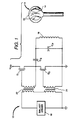
- FIG. 1 illustrates an exemplary Class-D power amplifier circuit which may be suitably controlled using the dual feedback system of the present invention.
- the Class-D system of Figure 1 is shown as comprising an electrodeless HID lamp 10 and associated Class-D ballast 12. It is to be understood, however, that the principles of the present invention apply equally to any Class-D power amplifier circuit; the Class-D HID lamp system is shown and described by way of example only.
- HID lamp 10 includes an arc tube 14 formed of a high-temperature glass, such as fused quartz, or an optically transparent ceramic, such as polycrystalline alumina.
- Arc tube 14 contains a fill which may comprise at least one metal halide, such as sodium iodide, and a buffer gas, such as xenon.
- Electrical power is applied to the HID lamp by an excitation coil 16 disposed about arc tube 14 which is driven by an RF signal via a ballast driver 18 and ballast 12.
- a suitable excitation coil 16 may comprise, for example, a two-turn coil having a configuration such as that described in commonly assigned, copending U.S.
- RF current in coil 16 results in a time-varying magnetic field which produces within arc tube 14 an electric field that completely closes upon itself.
- Current flows through the fill within arc tube 14 as a result of this solenoidal electric field, producing a toroidal arc discharge 20 in arc tube 14.
- ballast 12 comprises a Class-D power amplifier including two switching devices Q1 and Q2 connected in series with a dc power supply V DD in a half-bridge configuration.
- Switching devices Q1 and Q2 are illustrated as MOSFET's, but other types of switching devices having capacitive gates may be used, such as insulated gate bipolar transistors (IGBT's) or MOS-controlled thyristors (MCT's).
- IGBT's insulated gate bipolar transistors
- MCT's MOS-controlled thyristors
- Switching devices Q1 and Q2 are coupled to ballast driver 18 via input isolation transformers 22 and 24, respectively. In operation, the switching devices are driven alternately between cutoff and saturation such that one is conducting while the other one is turned off and vice versa.
- the Class-D ballast may be conveniently driven by a square wave signal.
- ballast driver 18 may comprise means for generating two out-of-phase sinusoidal signals, as described in commonly assigned U.S. Pat. No. 5,023,566 of S.A. El-Hamamsy and G. Jernakoff, issued June 11, 1991, which patent is incorporated by reference herein.
- a resonant load network is connected to the half-bridge at the junction between switching devices Q1 and Q2.
- a resonant load network may comprise a series, parallel or series/parallel resonant circuit, depending on the application.
- the resonant load network includes a series capacitor Cs which is employed both for resonant circuit tuning and blocking dc voltage.
- Capacitor C s is connected in series with the parallel combination of the excitation coil 16 of HID lamp 10 and a parallel tuning capacitor C p .
- the parallel combination of capacitor C p and coil 16 functions as an impedance transformer to reflect the impedance of the arc discharge 20 into the ballast load.
- capacitors C s and C p are chosen to ensure impedance matching for maximum efficiency. That is, these capacitors are chosen to ensure that the ballast load is designed for optimum values of resistance and phase angle.
- the excitation coil of the HID lamp acts as the primary of a loosely-coupled transformer, while the arc discharge acts as both a single-turn secondary and secondary load. The impedance of the arc discharge is reflected to the primary, or excitation coil, side of this loosely-coupled transformer.
- the parallel capacitor operates with the excitation coil to match the proper resistive load value, and the series capacitor acts with the combination of the excitation coil and parallel capacitor to yield the required phase angle.
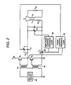
- Figure 2 illustrates a dual feedback system according to the present invention for controlling both the load amplitude and phase angle via phase control feedback loop 30 and amplitude control feedback loop 40, respectively, to maximize efficiency over a wide range of load voltages.
- L c represents the inductance and R c represents the resistance of coil 16
- L a represents the inductance and R a represents the resistance of the arc discharge
- k is the coupling coefficient between the coil and the arc discharge.
- the resonant circuit must have a variable impedance, e.g. by including a variable capacitance, a variable inductance, or a combination thereof.
- a suitable variable inductance may comprise, for example, a saturable core inductor of a type well-known in the art.
- a suitable variable capacitor may be of a type described in the Borowiec et al. U.S. patent 5,047,692, serial no. 472,144, cited hereinabove.
- the variable capacitor of the Borowiec et al. patent application comprises a fixed conductive plate and a substantially parallel, movable conductive plate with a dielectric disposed therebetween. Piezoelectric actuating means is used to vary the distance between the conductive plates by moving the movable plate with respect to the fixed plate. As a result, capacitance changes in inverse proportion to the distance moved.
- a control signal is provided to activate the piezoelectric actuating means to move the movable conductive plate.
- the control signal may provide either discrete control for movement of the movable conductive plate between a discrete number of predetermined operating positions, or it may provide continuous control for movement over a range of positions.
- Another suitable type of variable capacitor is a liquid crystal variable capacitor, such as that described in commonly assigned, copending U.S. patent 5,084,801, of S.A. El-Hamamsy and C.P. Yakymyshyn, filed February 19, 1991, which is incorporated by reference herein.
- the phase control feedback loop 30 controls the value of variable series capacitor C s in order to optimize the phase angle of the resonant load, thereby maximizing efficiency.
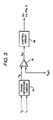
- a suitable phase control feedback loop is described in U.S. patent 5,063,332, cited hereinabove and illustrated in Figure 3.
- the voltage v c is sensed by a voltage sensor (not shown), and the current i L is sensed by a current sensor 32 ( Figure 2).
- a suitable voltage sensor may comprise, for example, a voltage dividing network of resistors or capacitors.
- a suitable current sensor may comprise, for example, a Hall-effect sensor or a current viewing resistor, such as that described in commonly assigned, copending U.S. patent application no. 632,213 of S.A. El-Hamamsy, filed December 21, 1990, which is incorporated by reference herein.
- the sensed voltage and current are provided as input signals to a phase detector circuit 34 for determining the phase angle ⁇ therebetween.
- the output signal from phase detector 34 comprises a voltage V ⁇ proportional to the measured phase angle ⁇ .
- the voltage V ⁇ is compared in an error amplifier 36 to a reference voltage V ref 1, and the resulting error signal V e1 is supplied as the input to a control circuit 38 for continuously tuning the variable capacitor C s during all operating conditions.
- a second feedback loop i.e. the amplitude feedback control loop 40
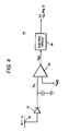
- a preferred implementation of the amplitude feedback loop 40 is illustrated in Figure 4.
- the current i L is rectified by rectifier 42 and filtered by filter capacitor C f to yield a dc voltage V iL that is proportional to the load current i L .
- the voltage V iL is compared to a reference voltage V ref 2 in comparator 44.
- the resulting error voltage V e 2 is provided to a control circuit 46 for controlling the variable parallel capacitor C p .
- a suitable control circuit comprises a pulse width modulation (PWM) circuit.
- a suitable PWM circuit is a type UC3525A manufactured by Unitrode Integrated Circuits Corporation.
- the series capacitor is varied by the phase control feedback loop to match the particular phase angle.
- the magnitude of the load is affected somewhat, so that the parallel capacitor C p must again be adjusted.
- the optimal load impedance may be achieved.
- variations in the phase angle and amplitude will converge to the optimal load as long as the extent of variation of capacitors C S and C p is limited.
Landscapes
- Circuit Arrangements For Discharge Lamps (AREA)
- Amplifiers (AREA)
Applications Claiming Priority (2)
| Application Number | Priority Date | Filing Date | Title |
|---|---|---|---|
| US07/745,653 US5118997A (en) | 1991-08-16 | 1991-08-16 | Dual feedback control for a high-efficiency class-d power amplifier circuit |
| US745653 | 1991-08-16 |
Publications (1)
| Publication Number | Publication Date |
|---|---|
| EP0529901A1 true EP0529901A1 (de) | 1993-03-03 |
Family
ID=24997652
Family Applications (1)
| Application Number | Title | Priority Date | Filing Date |
|---|---|---|---|
| EP92307496A Withdrawn EP0529901A1 (de) | 1991-08-16 | 1992-08-14 | Regelungsschaltung für einen zweifach rückgekoppelten Klasse-D Leistungsverstärker mit hohem Wirkungsgrad |
Country Status (4)
| Country | Link |
|---|---|
| US (1) | US5118997A (de) |
| EP (1) | EP0529901A1 (de) |
| JP (1) | JPH0773168B2 (de) |
| CA (1) | CA2072396A1 (de) |
Cited By (4)
| Publication number | Priority date | Publication date | Assignee | Title |
|---|---|---|---|---|
| WO1999008373A3 (en) * | 1997-08-12 | 1999-04-15 | Koninkl Philips Electronics Nv | Voltage regulation scheme for power supply having a voltage-fed inverter |
| EP1194016A3 (de) * | 2000-09-27 | 2002-04-24 | Patent-Treuhand-Gesellschaft für elektrische Glühlampen mbH | EVG für Gasentladungslampen mit Phasen-Detektion |
| EP1475886A1 (de) * | 2003-05-06 | 2004-11-10 | Fraunhofer-Gesellschaft zur Förderung der angewandten Forschung e.V. | Verfahren und Vorrichtung zum Einstellen einer Resonanzschaltung für eine minimale Leistungsaufnahme eines Verstärkers |
| US6933682B2 (en) | 2002-08-30 | 2005-08-23 | Patent Trauhand Gesellschaft Fur Elektrische Gluhlampen Mbh | Method for operating fluorescent lamps and ballast |
Families Citing this family (142)
| Publication number | Priority date | Publication date | Assignee | Title |
|---|---|---|---|---|
| WO1993021685A1 (en) * | 1992-04-16 | 1993-10-28 | Advanced Energy Industries, Inc. | Stabilizer for switch-mode powered rf plasma processing |
| US5306986A (en) * | 1992-05-20 | 1994-04-26 | Diablo Research Corporation | Zero-voltage complementary switching high efficiency class D amplifier |
| TW214598B (en) * | 1992-05-20 | 1993-10-11 | Diablo Res Corp | Impedance matching and filter network for use with electrodeless discharge lamp |
| EP0643900B1 (de) * | 1992-06-05 | 1998-09-02 | Diablo Research Corporation | Elektrodenlose entladungslampe mit push-pull e klasse verstärker und spule |
| TW210397B (en) * | 1992-06-05 | 1993-08-01 | Diablo Res Corp | Base mechanism to attach an electrodeless discharge light bulb to a socket in a standard lamp harp structure |
| US5332970A (en) * | 1992-06-25 | 1994-07-26 | General Electric Company | Method for measuring the impedance of an electrodeless arc discharge lamp |
| DE69315625T2 (de) * | 1992-06-30 | 1998-07-16 | Toshiba Lighting & Technology | Umrichterschaltung und Beleuchtungsgerät für eine elektrodenlose Entladungslampe mit solch einer Umrichterschaltung |
| US5382878A (en) * | 1992-12-24 | 1995-01-17 | General Electric Company | Auto-starting system for an electrodeless high intensity discharge lamp |
| JP3234361B2 (ja) | 1993-07-27 | 2001-12-04 | 松下電工株式会社 | 無電極放電灯点灯装置 |
| KR960010713B1 (ko) * | 1993-08-17 | 1996-08-07 | 삼성전자 주식회사 | 공진형 컨버터의 영전압 스위칭 제어장치 및 이를 이용한 전자식 안정기 |
| US5463285A (en) * | 1994-03-14 | 1995-10-31 | General Electric Company | Variable capacitor with very fine resolution |
| US5600187A (en) * | 1994-06-27 | 1997-02-04 | General Electric Company | Electronically controllable capacitors using power MOSFET's |
| WO1996031899A1 (en) * | 1995-04-07 | 1996-10-10 | Advanced Energy Industries, Inc. | Adjustable energy quantum thin film plasma processing system |
| KR100411533B1 (ko) * | 1995-11-29 | 2004-04-03 | 코닌클리케 필립스 일렉트로닉스 엔.브이. | 유선전기통신용터미널 |
| US5917286A (en) | 1996-05-08 | 1999-06-29 | Advanced Energy Industries, Inc. | Pulsed direct current power supply configurations for generating plasmas |
| US6229393B1 (en) | 1997-01-22 | 2001-05-08 | Storz Endoskop Gmbh | High frequency power generator |
| EP0962048B1 (de) | 1997-02-24 | 2003-06-11 | Advanced Energy Industries, Inc. | Hochleistungs rf-plasmaprozesssystem |
| DE19731691C1 (de) * | 1997-07-23 | 1998-10-08 | Siemens Ag | Leistungs-Schaltverstärker |
| US6137237A (en) | 1998-01-13 | 2000-10-24 | Fusion Lighting, Inc. | High frequency inductive lamp and power oscillator |
| US6313587B1 (en) | 1998-01-13 | 2001-11-06 | Fusion Lighting, Inc. | High frequency inductive lamp and power oscillator |
| US6043613A (en) * | 1998-08-26 | 2000-03-28 | General Electric Company | Starting system for electrodeless metal halide discharge lamps |
| US6100652A (en) * | 1998-11-12 | 2000-08-08 | Osram Sylvania Inc. | Ballast with starting circuit for high-intensity discharge lamps |
| US6737809B2 (en) * | 2000-07-31 | 2004-05-18 | Luxim Corporation | Plasma lamp with dielectric waveguide |
| US6549071B1 (en) * | 2000-09-12 | 2003-04-15 | Silicon Laboratories, Inc. | Power amplifier circuitry and method using an inductance coupled to power amplifier switching devices |
| US6462620B1 (en) | 2000-09-12 | 2002-10-08 | Silicon Laboratories, Inc. | RF power amplifier circuitry and method for amplifying signals |
| US6448847B1 (en) | 2000-09-12 | 2002-09-10 | Silicon Laboratories, Inc. | Apparatus and method for providing differential-to-single ended conversion and impedance transformation |
| US6362606B1 (en) | 2000-09-12 | 2002-03-26 | Silicon Laboratories, Inc | Method and apparatus for regulating a voltage |
| US6917245B2 (en) | 2000-09-12 | 2005-07-12 | Silicon Laboratories, Inc. | Absolute power detector |
| US6392488B1 (en) | 2000-09-12 | 2002-05-21 | Silicon Laboratories, Inc. | Dual oxide gate device and method for providing the same |
| WO2002030160A1 (en) * | 2000-10-06 | 2002-04-11 | Central Research Laboratories Limited | A power supply for driving a discharge lamp |
| US6300830B1 (en) * | 2000-12-29 | 2001-10-09 | Ericsson Inc | Multiplexed input envelope restoration scheme for linear high-efficiency power amplification |
| US6828859B2 (en) * | 2001-08-17 | 2004-12-07 | Silicon Laboratories, Inc. | Method and apparatus for protecting devices in an RF power amplifier |
| US6664742B2 (en) * | 2002-01-11 | 2003-12-16 | Koninklijke Philips Electronics N.V. | Filament cut-back circuit |
| US6894565B1 (en) * | 2002-12-03 | 2005-05-17 | Silicon Laboratories, Inc. | Fast settling power amplifier regulator |
| US6897730B2 (en) * | 2003-03-04 | 2005-05-24 | Silicon Laboratories Inc. | Method and apparatus for controlling the output power of a power amplifier |
| US7078963B1 (en) * | 2003-03-21 | 2006-07-18 | D2Audio Corporation | Integrated PULSHI mode with shutdown |
| US7929718B1 (en) | 2003-05-12 | 2011-04-19 | D2Audio Corporation | Systems and methods for switching and mixing signals in a multi-channel amplifier |
| US7825543B2 (en) * | 2005-07-12 | 2010-11-02 | Massachusetts Institute Of Technology | Wireless energy transfer |
| KR101118710B1 (ko) * | 2005-07-12 | 2012-03-13 | 메사추세츠 인스티튜트 오브 테크놀로지 | 무선 비-방사성 에너지 전달 |
| WO2008048978A2 (en) * | 2006-10-16 | 2008-04-24 | Luxim Corporation | Electrodeless plasma lamp systems and methods |
| US20110043111A1 (en) * | 2006-10-16 | 2011-02-24 | Gregg Hollingsworth | Rf feed configurations and assembly for plasma lamp |
| US8805530B2 (en) * | 2007-06-01 | 2014-08-12 | Witricity Corporation | Power generation for implantable devices |
| US9421388B2 (en) | 2007-06-01 | 2016-08-23 | Witricity Corporation | Power generation for implantable devices |
| WO2009140506A1 (en) | 2008-05-14 | 2009-11-19 | Massachusetts Institute Of Technology | Wireless energy transfer, including interference enhancement |
| US8772973B2 (en) | 2008-09-27 | 2014-07-08 | Witricity Corporation | Integrated resonator-shield structures |
| US9515494B2 (en) | 2008-09-27 | 2016-12-06 | Witricity Corporation | Wireless power system including impedance matching network |
| US8723366B2 (en) | 2008-09-27 | 2014-05-13 | Witricity Corporation | Wireless energy transfer resonator enclosures |
| US8461721B2 (en) | 2008-09-27 | 2013-06-11 | Witricity Corporation | Wireless energy transfer using object positioning for low loss |
| US8963488B2 (en) | 2008-09-27 | 2015-02-24 | Witricity Corporation | Position insensitive wireless charging |
| US8569914B2 (en) | 2008-09-27 | 2013-10-29 | Witricity Corporation | Wireless energy transfer using object positioning for improved k |
| US8587155B2 (en) | 2008-09-27 | 2013-11-19 | Witricity Corporation | Wireless energy transfer using repeater resonators |
| US8957549B2 (en) | 2008-09-27 | 2015-02-17 | Witricity Corporation | Tunable wireless energy transfer for in-vehicle applications |
| US8669676B2 (en) | 2008-09-27 | 2014-03-11 | Witricity Corporation | Wireless energy transfer across variable distances using field shaping with magnetic materials to improve the coupling factor |
| US8912687B2 (en) | 2008-09-27 | 2014-12-16 | Witricity Corporation | Secure wireless energy transfer for vehicle applications |
| US8907531B2 (en) | 2008-09-27 | 2014-12-09 | Witricity Corporation | Wireless energy transfer with variable size resonators for medical applications |
| US9105959B2 (en) | 2008-09-27 | 2015-08-11 | Witricity Corporation | Resonator enclosure |
| US8629578B2 (en) | 2008-09-27 | 2014-01-14 | Witricity Corporation | Wireless energy transfer systems |
| US9160203B2 (en) | 2008-09-27 | 2015-10-13 | Witricity Corporation | Wireless powered television |
| US9601270B2 (en) | 2008-09-27 | 2017-03-21 | Witricity Corporation | Low AC resistance conductor designs |
| US9577436B2 (en) | 2008-09-27 | 2017-02-21 | Witricity Corporation | Wireless energy transfer for implantable devices |
| US8643326B2 (en) | 2008-09-27 | 2014-02-04 | Witricity Corporation | Tunable wireless energy transfer systems |
| US9396867B2 (en) | 2008-09-27 | 2016-07-19 | Witricity Corporation | Integrated resonator-shield structures |
| US8946938B2 (en) | 2008-09-27 | 2015-02-03 | Witricity Corporation | Safety systems for wireless energy transfer in vehicle applications |
| US9035499B2 (en) | 2008-09-27 | 2015-05-19 | Witricity Corporation | Wireless energy transfer for photovoltaic panels |
| US8686598B2 (en) | 2008-09-27 | 2014-04-01 | Witricity Corporation | Wireless energy transfer for supplying power and heat to a device |
| US9184595B2 (en) | 2008-09-27 | 2015-11-10 | Witricity Corporation | Wireless energy transfer in lossy environments |
| WO2010036980A1 (en) * | 2008-09-27 | 2010-04-01 | Witricity Corporation | Wireless energy transfer systems |
| US8482158B2 (en) | 2008-09-27 | 2013-07-09 | Witricity Corporation | Wireless energy transfer using variable size resonators and system monitoring |
| US9246336B2 (en) | 2008-09-27 | 2016-01-26 | Witricity Corporation | Resonator optimizations for wireless energy transfer |
| US9318922B2 (en) | 2008-09-27 | 2016-04-19 | Witricity Corporation | Mechanically removable wireless power vehicle seat assembly |
| US9744858B2 (en) | 2008-09-27 | 2017-08-29 | Witricity Corporation | System for wireless energy distribution in a vehicle |
| US8922066B2 (en) | 2008-09-27 | 2014-12-30 | Witricity Corporation | Wireless energy transfer with multi resonator arrays for vehicle applications |
| US8461720B2 (en) * | 2008-09-27 | 2013-06-11 | Witricity Corporation | Wireless energy transfer using conducting surfaces to shape fields and reduce loss |
| US9106203B2 (en) | 2008-09-27 | 2015-08-11 | Witricity Corporation | Secure wireless energy transfer in medical applications |
| US8441154B2 (en) | 2008-09-27 | 2013-05-14 | Witricity Corporation | Multi-resonator wireless energy transfer for exterior lighting |
| US8471410B2 (en) | 2008-09-27 | 2013-06-25 | Witricity Corporation | Wireless energy transfer over distance using field shaping to improve the coupling factor |
| US8933594B2 (en) | 2008-09-27 | 2015-01-13 | Witricity Corporation | Wireless energy transfer for vehicles |
| US8552592B2 (en) * | 2008-09-27 | 2013-10-08 | Witricity Corporation | Wireless energy transfer with feedback control for lighting applications |
| US8598743B2 (en) | 2008-09-27 | 2013-12-03 | Witricity Corporation | Resonator arrays for wireless energy transfer |
| US8901779B2 (en) | 2008-09-27 | 2014-12-02 | Witricity Corporation | Wireless energy transfer with resonator arrays for medical applications |
| US8901778B2 (en) | 2008-09-27 | 2014-12-02 | Witricity Corporation | Wireless energy transfer with variable size resonators for implanted medical devices |
| US8692410B2 (en) * | 2008-09-27 | 2014-04-08 | Witricity Corporation | Wireless energy transfer with frequency hopping |
| US8466583B2 (en) | 2008-09-27 | 2013-06-18 | Witricity Corporation | Tunable wireless energy transfer for outdoor lighting applications |
| US8410636B2 (en) | 2008-09-27 | 2013-04-02 | Witricity Corporation | Low AC resistance conductor designs |
| US9093853B2 (en) | 2008-09-27 | 2015-07-28 | Witricity Corporation | Flexible resonator attachment |
| US8461722B2 (en) | 2008-09-27 | 2013-06-11 | Witricity Corporation | Wireless energy transfer using conducting surfaces to shape field and improve K |
| US8487480B1 (en) | 2008-09-27 | 2013-07-16 | Witricity Corporation | Wireless energy transfer resonator kit |
| US9601261B2 (en) | 2008-09-27 | 2017-03-21 | Witricity Corporation | Wireless energy transfer using repeater resonators |
| US8947186B2 (en) | 2008-09-27 | 2015-02-03 | Witricity Corporation | Wireless energy transfer resonator thermal management |
| US8324759B2 (en) * | 2008-09-27 | 2012-12-04 | Witricity Corporation | Wireless energy transfer using magnetic materials to shape field and reduce loss |
| US8497601B2 (en) | 2008-09-27 | 2013-07-30 | Witricity Corporation | Wireless energy transfer converters |
| US9601266B2 (en) | 2008-09-27 | 2017-03-21 | Witricity Corporation | Multiple connected resonators with a single electronic circuit |
| US8476788B2 (en) | 2008-09-27 | 2013-07-02 | Witricity Corporation | Wireless energy transfer with high-Q resonators using field shaping to improve K |
| US8937408B2 (en) | 2008-09-27 | 2015-01-20 | Witricity Corporation | Wireless energy transfer for medical applications |
| US8692412B2 (en) | 2008-09-27 | 2014-04-08 | Witricity Corporation | Temperature compensation in a wireless transfer system |
| US8400017B2 (en) | 2008-09-27 | 2013-03-19 | Witricity Corporation | Wireless energy transfer for computer peripheral applications |
| US9544683B2 (en) | 2008-09-27 | 2017-01-10 | Witricity Corporation | Wirelessly powered audio devices |
| US9065423B2 (en) | 2008-09-27 | 2015-06-23 | Witricity Corporation | Wireless energy distribution system |
| US8928276B2 (en) | 2008-09-27 | 2015-01-06 | Witricity Corporation | Integrated repeaters for cell phone applications |
| US8587153B2 (en) | 2008-09-27 | 2013-11-19 | Witricity Corporation | Wireless energy transfer using high Q resonators for lighting applications |
| US8304935B2 (en) * | 2008-09-27 | 2012-11-06 | Witricity Corporation | Wireless energy transfer using field shaping to reduce loss |
| EP2345100B1 (de) | 2008-10-01 | 2018-12-05 | Massachusetts Institute of Technology | Effiziente nahfeld-drahtlosenergieübertragung anhand adiabatischer systemveränderungen |
| US8659335B2 (en) * | 2009-06-25 | 2014-02-25 | Mks Instruments, Inc. | Method and system for controlling radio frequency power |
| JP2011215882A (ja) * | 2010-03-31 | 2011-10-27 | Fujitsu Ltd | 電力制御装置及びこれを用いた情報通信装置 |
| US9602168B2 (en) | 2010-08-31 | 2017-03-21 | Witricity Corporation | Communication in wireless energy transfer systems |
| US8553909B2 (en) | 2011-04-29 | 2013-10-08 | Smsc Holdings S.A.R.L. | Low-power class D amplifier using multistate analog feedback loops |
| US9948145B2 (en) | 2011-07-08 | 2018-04-17 | Witricity Corporation | Wireless power transfer for a seat-vest-helmet system |
| CA2844062C (en) | 2011-08-04 | 2017-03-28 | Witricity Corporation | Tunable wireless power architectures |
| JP6185472B2 (ja) | 2011-09-09 | 2017-08-23 | ワイトリシティ コーポレーションWitricity Corporation | ワイヤレスエネルギー伝送システムにおける異物検出 |
| US20130062966A1 (en) | 2011-09-12 | 2013-03-14 | Witricity Corporation | Reconfigurable control architectures and algorithms for electric vehicle wireless energy transfer systems |
| US9318257B2 (en) | 2011-10-18 | 2016-04-19 | Witricity Corporation | Wireless energy transfer for packaging |
| HK1200602A1 (en) | 2011-11-04 | 2015-08-07 | WiTricity公司 | Wireless energy transfer modeling tool |
| WO2013113017A1 (en) | 2012-01-26 | 2013-08-01 | Witricity Corporation | Wireless energy transfer with reduced fields |
| US9343922B2 (en) | 2012-06-27 | 2016-05-17 | Witricity Corporation | Wireless energy transfer for rechargeable batteries |
| US9287607B2 (en) | 2012-07-31 | 2016-03-15 | Witricity Corporation | Resonator fine tuning |
| US9595378B2 (en) | 2012-09-19 | 2017-03-14 | Witricity Corporation | Resonator enclosure |
| WO2014063159A2 (en) | 2012-10-19 | 2014-04-24 | Witricity Corporation | Foreign object detection in wireless energy transfer systems |
| US9842684B2 (en) | 2012-11-16 | 2017-12-12 | Witricity Corporation | Systems and methods for wireless power system with improved performance and/or ease of use |
| EP3039770B1 (de) | 2013-08-14 | 2020-01-22 | WiTricity Corporation | Impedanzabstimmung |
| CN104579192B (zh) * | 2013-10-10 | 2018-06-05 | 通用电气公司 | 使用反馈控制的射频信号放大系统及方法 |
| KR101943082B1 (ko) * | 2014-01-23 | 2019-04-18 | 한국전자통신연구원 | 무선 전력 송신 장치, 무선 전력 수신 장치, 및 무선 전력 전송 시스템 |
| US9780573B2 (en) | 2014-02-03 | 2017-10-03 | Witricity Corporation | Wirelessly charged battery system |
| US9952266B2 (en) | 2014-02-14 | 2018-04-24 | Witricity Corporation | Object detection for wireless energy transfer systems |
| US9842687B2 (en) | 2014-04-17 | 2017-12-12 | Witricity Corporation | Wireless power transfer systems with shaped magnetic components |
| WO2015161035A1 (en) | 2014-04-17 | 2015-10-22 | Witricity Corporation | Wireless power transfer systems with shield openings |
| US9837860B2 (en) | 2014-05-05 | 2017-12-05 | Witricity Corporation | Wireless power transmission systems for elevators |
| WO2015171910A1 (en) | 2014-05-07 | 2015-11-12 | Witricity Corporation | Foreign object detection in wireless energy transfer systems |
| US9954375B2 (en) | 2014-06-20 | 2018-04-24 | Witricity Corporation | Wireless power transfer systems for surfaces |
| US10574091B2 (en) | 2014-07-08 | 2020-02-25 | Witricity Corporation | Enclosures for high power wireless power transfer systems |
| WO2016007674A1 (en) | 2014-07-08 | 2016-01-14 | Witricity Corporation | Resonator balancing in wireless power transfer systems |
| US10512553B2 (en) * | 2014-07-30 | 2019-12-24 | The Alfred E. Mann Foundation For Scientific Research | Inductive link coil de-tuning compensation and control |
| US9843217B2 (en) | 2015-01-05 | 2017-12-12 | Witricity Corporation | Wireless energy transfer for wearables |
| US10248899B2 (en) | 2015-10-06 | 2019-04-02 | Witricity Corporation | RFID tag and transponder detection in wireless energy transfer systems |
| EP3362804B1 (de) | 2015-10-14 | 2024-01-17 | WiTricity Corporation | Phasen- und amplitudendetektion in systemen zur drahtlosen energieübertragung |
| WO2017070227A1 (en) | 2015-10-19 | 2017-04-27 | Witricity Corporation | Foreign object detection in wireless energy transfer systems |
| WO2017070009A1 (en) | 2015-10-22 | 2017-04-27 | Witricity Corporation | Dynamic tuning in wireless energy transfer systems |
| US10075019B2 (en) | 2015-11-20 | 2018-09-11 | Witricity Corporation | Voltage source isolation in wireless power transfer systems |
| CN109075613B (zh) | 2016-02-02 | 2022-05-31 | 韦特里西提公司 | 控制无线电力传输系统 |
| WO2017139406A1 (en) | 2016-02-08 | 2017-08-17 | Witricity Corporation | Pwm capacitor control |
| WO2019006376A1 (en) | 2017-06-29 | 2019-01-03 | Witricity Corporation | PROTECTION AND CONTROL OF WIRELESS POWER SYSTEMS |
| US11670961B2 (en) | 2018-12-14 | 2023-06-06 | Otis Elevator Company | Closed loop control wireless power transmission system for conveyance system |
| US12024039B2 (en) | 2021-12-07 | 2024-07-02 | Arnold Chase | Vehicle self-centered charging system |
Citations (4)
| Publication number | Priority date | Publication date | Assignee | Title |
|---|---|---|---|---|
| EP0097450A1 (de) * | 1982-06-18 | 1984-01-04 | Eg & G, Inc. | Speiseschaltung für Alkalidampflampen |
| US4733200A (en) * | 1986-10-14 | 1988-03-22 | Motorola, Inc. | Controlled feedback path voltage controlled oscillator |
| EP0374617A2 (de) * | 1988-12-21 | 1990-06-27 | Hella KG Hueck & Co. | Einrichtung zum Zünden und Betreiben elektrischer Gasentladungslampen |
| WO1990012478A1 (en) * | 1989-04-12 | 1990-10-18 | Peroxidation Systems, Inc. | Adaptive resonant ballast for discharge lamps |
Family Cites Families (7)
| Publication number | Priority date | Publication date | Assignee | Title |
|---|---|---|---|---|
| US3899745A (en) * | 1974-04-26 | 1975-08-12 | Nasa | Isolated output system for a class D switching-mode amplifier |
| US4383203A (en) * | 1981-06-29 | 1983-05-10 | Litek International Inc. | Circuit means for efficiently driving an electrodeless discharge lamp |
| US4783615A (en) * | 1985-06-26 | 1988-11-08 | General Electric Company | Electrodeless high pressure sodium iodide arc lamp |
| US4628275A (en) * | 1985-07-29 | 1986-12-09 | Rockwell International Corporation | Efficient power amplifier for high capacitive devices |
| US4812702A (en) * | 1987-12-28 | 1989-03-14 | General Electric Company | Excitation coil for hid electrodeless discharge lamp |
| US5023566A (en) * | 1989-12-21 | 1991-06-11 | General Electric Company | Driver for a high efficiency, high frequency Class-D power amplifier |
| US5063332A (en) * | 1990-12-21 | 1991-11-05 | General Electric Company | Feedback control system for a high-efficiency class-D power amplifier circuit |
-
1991
- 1991-08-16 US US07/745,653 patent/US5118997A/en not_active Expired - Fee Related
-
1992
- 1992-06-25 CA CA002072396A patent/CA2072396A1/en not_active Abandoned
- 1992-08-11 JP JP4213937A patent/JPH0773168B2/ja not_active Expired - Lifetime
- 1992-08-14 EP EP92307496A patent/EP0529901A1/de not_active Withdrawn
Patent Citations (4)
| Publication number | Priority date | Publication date | Assignee | Title |
|---|---|---|---|---|
| EP0097450A1 (de) * | 1982-06-18 | 1984-01-04 | Eg & G, Inc. | Speiseschaltung für Alkalidampflampen |
| US4733200A (en) * | 1986-10-14 | 1988-03-22 | Motorola, Inc. | Controlled feedback path voltage controlled oscillator |
| EP0374617A2 (de) * | 1988-12-21 | 1990-06-27 | Hella KG Hueck & Co. | Einrichtung zum Zünden und Betreiben elektrischer Gasentladungslampen |
| WO1990012478A1 (en) * | 1989-04-12 | 1990-10-18 | Peroxidation Systems, Inc. | Adaptive resonant ballast for discharge lamps |
Cited By (5)
| Publication number | Priority date | Publication date | Assignee | Title |
|---|---|---|---|---|
| WO1999008373A3 (en) * | 1997-08-12 | 1999-04-15 | Koninkl Philips Electronics Nv | Voltage regulation scheme for power supply having a voltage-fed inverter |
| EP1194016A3 (de) * | 2000-09-27 | 2002-04-24 | Patent-Treuhand-Gesellschaft für elektrische Glühlampen mbH | EVG für Gasentladungslampen mit Phasen-Detektion |
| US6933682B2 (en) | 2002-08-30 | 2005-08-23 | Patent Trauhand Gesellschaft Fur Elektrische Gluhlampen Mbh | Method for operating fluorescent lamps and ballast |
| EP1395096A3 (de) * | 2002-08-30 | 2005-09-07 | Patent-Treuhand-Gesellschaft für elektrische Glühlampen mbH | Verfahren zum Betreiben von Leuchtstofflampen und Vorschaltgerät |
| EP1475886A1 (de) * | 2003-05-06 | 2004-11-10 | Fraunhofer-Gesellschaft zur Förderung der angewandten Forschung e.V. | Verfahren und Vorrichtung zum Einstellen einer Resonanzschaltung für eine minimale Leistungsaufnahme eines Verstärkers |
Also Published As
| Publication number | Publication date |
|---|---|
| US5118997A (en) | 1992-06-02 |
| CA2072396A1 (en) | 1993-02-17 |
| JPH0773168B2 (ja) | 1995-08-02 |
| JPH05206750A (ja) | 1993-08-13 |
Similar Documents
| Publication | Publication Date | Title |
|---|---|---|
| US5118997A (en) | Dual feedback control for a high-efficiency class-d power amplifier circuit | |
| US5075600A (en) | Piezoelectrically actuated variable capacitor | |
| US5063332A (en) | Feedback control system for a high-efficiency class-D power amplifier circuit | |
| US5084801A (en) | Liquid crystal variable capacitor and high intensity discharge lamp ballast employing same | |
| EP0458546B1 (de) | Zündschaltung für eine elektrodenlose Starkentladungslampe | |
| US5463285A (en) | Variable capacitor with very fine resolution | |
| EP0577105B1 (de) | Umrichterschaltung und Beleuchtungsgerät für eine elektrodenlose Entladungslampe mit solch einer Umrichterschaltung | |
| EP0679050A1 (de) | Impendanzanpassungsschaltung für das Vorschaltgerät einer Elektrodenlosenentladungslampe | |
| US5134345A (en) | Feedback system for stabilizing the arc discharge of a high intensity discharge lamp | |
| US5600187A (en) | Electronically controllable capacitors using power MOSFET's | |
| US5057750A (en) | Two-stage resonant starting circuit for an electrodeless high intensity discharge lamp | |
| US5047692A (en) | Integrated tuning capacitor network and heat sink for an electrodeless high intensity discharge lamp ballast | |
| US5103140A (en) | Starting circuit for an electrodeless high intensity discharge lamp | |
| US5479102A (en) | Simulated load circuit for simulating the arc impedance of an electrodless discharge lamp | |
| US5175476A (en) | Magnetically tunable starting circuit for an electrodeless high intensity discharge lamp | |
| EP0520715B1 (de) | Zündschaltung für eine Entladungslampe hoher Intensität ohne Elektrode | |
| US5153484A (en) | Electrodeless high intensity discharge lamp excitation coil and ballast configuration for maximum efficiency | |
| US5047893A (en) | High-frequency capacitor | |
| WO2006137607A1 (en) | Adaptive coupling circuits using multi resonance tanks | |
| JPH0660989A (ja) | 無電極放電ランプ点灯装置 | |
| JPH0745382A (ja) | 無電極放電ランプ点灯装置 | |
| JPH06111972A (ja) | 無電極放電ランプ点灯装置 | |
| JPH1070887A (ja) | 電源装置 | |
| JPH07235389A (ja) | 無電極放電灯点灯装置 |
Legal Events
| Date | Code | Title | Description |
|---|---|---|---|
| PUAI | Public reference made under article 153(3) epc to a published international application that has entered the european phase |
Free format text: ORIGINAL CODE: 0009012 |
|
| AK | Designated contracting states |
Kind code of ref document: A1 Designated state(s): DE FR GB IT NL |
|
| 17P | Request for examination filed |
Effective date: 19930830 |
|
| 17Q | First examination report despatched |
Effective date: 19951110 |
|
| STAA | Information on the status of an ep patent application or granted ep patent |
Free format text: STATUS: THE APPLICATION IS DEEMED TO BE WITHDRAWN |
|
| 18D | Application deemed to be withdrawn |
Effective date: 19960301 |