EP0529686A2 - Method of compensating for changes in the flow characteristic of a fluid being dispensed from a nozzle - Google Patents
Method of compensating for changes in the flow characteristic of a fluid being dispensed from a nozzle Download PDFInfo
- Publication number
- EP0529686A2 EP0529686A2 EP92117048A EP92117048A EP0529686A2 EP 0529686 A2 EP0529686 A2 EP 0529686A2 EP 92117048 A EP92117048 A EP 92117048A EP 92117048 A EP92117048 A EP 92117048A EP 0529686 A2 EP0529686 A2 EP 0529686A2
- Authority
- EP
- European Patent Office
- Prior art keywords
- signal
- nozzle
- fluid
- flow
- setpoint
- Prior art date
- Legal status (The legal status is an assumption and is not a legal conclusion. Google has not performed a legal analysis and makes no representation as to the accuracy of the status listed.)
- Granted
Links
Images


Classifications
-
- B—PERFORMING OPERATIONS; TRANSPORTING
- B05—SPRAYING OR ATOMISING IN GENERAL; APPLYING FLUENT MATERIALS TO SURFACES, IN GENERAL
- B05B—SPRAYING APPARATUS; ATOMISING APPARATUS; NOZZLES
- B05B12/00—Arrangements for controlling delivery; Arrangements for controlling the spray area
- B05B12/02—Arrangements for controlling delivery; Arrangements for controlling the spray area for controlling time, or sequence, of delivery
-
- G—PHYSICS
- G05—CONTROLLING; REGULATING
- G05D—SYSTEMS FOR CONTROLLING OR REGULATING NON-ELECTRIC VARIABLES
- G05D7/00—Control of flow
- G05D7/06—Control of flow characterised by the use of electric means
- G05D7/0617—Control of flow characterised by the use of electric means specially adapted for fluid materials
- G05D7/0629—Control of flow characterised by the use of electric means specially adapted for fluid materials characterised by the type of regulator means
- G05D7/0635—Control of flow characterised by the use of electric means specially adapted for fluid materials characterised by the type of regulator means by action on throttling means
-
- B—PERFORMING OPERATIONS; TRANSPORTING
- B05—SPRAYING OR ATOMISING IN GENERAL; APPLYING FLUENT MATERIALS TO SURFACES, IN GENERAL
- B05B—SPRAYING APPARATUS; ATOMISING APPARATUS; NOZZLES
- B05B12/00—Arrangements for controlling delivery; Arrangements for controlling the spray area
- B05B12/08—Arrangements for controlling delivery; Arrangements for controlling the spray area responsive to condition of liquid or other fluent material to be discharged, of ambient medium or of target ; responsive to condition of spray devices or of supply means, e.g. pipes, pumps or their drive means
- B05B12/085—Arrangements for controlling delivery; Arrangements for controlling the spray area responsive to condition of liquid or other fluent material to be discharged, of ambient medium or of target ; responsive to condition of spray devices or of supply means, e.g. pipes, pumps or their drive means responsive to flow or pressure of liquid or other fluent material to be discharged
-
- B—PERFORMING OPERATIONS; TRANSPORTING
- B05—SPRAYING OR ATOMISING IN GENERAL; APPLYING FLUENT MATERIALS TO SURFACES, IN GENERAL
- B05B—SPRAYING APPARATUS; ATOMISING APPARATUS; NOZZLES
- B05B13/00—Machines or plants for applying liquids or other fluent materials to surfaces of objects or other work by spraying, not covered by groups B05B1/00 - B05B11/00
- B05B13/02—Means for supporting work; Arrangement or mounting of spray heads; Adaptation or arrangement of means for feeding work
- B05B13/04—Means for supporting work; Arrangement or mounting of spray heads; Adaptation or arrangement of means for feeding work the spray heads being moved during spraying operation
- B05B13/0431—Means for supporting work; Arrangement or mounting of spray heads; Adaptation or arrangement of means for feeding work the spray heads being moved during spraying operation with spray heads moved by robots or articulated arms, e.g. for applying liquid or other fluent material to 3D-surfaces
-
- B—PERFORMING OPERATIONS; TRANSPORTING
- B05—SPRAYING OR ATOMISING IN GENERAL; APPLYING FLUENT MATERIALS TO SURFACES, IN GENERAL
- B05C—APPARATUS FOR APPLYING FLUENT MATERIALS TO SURFACES, IN GENERAL
- B05C5/00—Apparatus in which liquid or other fluent material is projected, poured or allowed to flow on to the surface of the work
- B05C5/02—Apparatus in which liquid or other fluent material is projected, poured or allowed to flow on to the surface of the work the liquid or other fluent material being discharged through an outlet orifice by pressure, e.g. from an outlet device in contact or almost in contact, with the work
- B05C5/0225—Apparatus in which liquid or other fluent material is projected, poured or allowed to flow on to the surface of the work the liquid or other fluent material being discharged through an outlet orifice by pressure, e.g. from an outlet device in contact or almost in contact, with the work characterised by flow controlling means, e.g. valves, located proximate the outlet
Definitions
- the present invention relates to a method for dispensing viscous fluid materials such as lubricants, sealants and adhesives onto a workpiece at a controlled rate of a flow which can be adjusted to compensate for changes in the relative speed between the dispenser and the workpiece.
- viscous fluid materials such as lubricants, sealants and adhesives onto a workpiece at a controlled rate of a flow which can be adjusted to compensate for changes in the relative speed between the dispenser and the workpiece.
- the fluid being dispensed may either be projected some distance from the nozzle in a high velocity stream or extruded from the nozzle at lower velocity with the nozzle located closer to the workpiece.
- the amount of material applied per unit of lineal distance along the head will vary according to both the flow rate of material discharged from the dispensing nozzle and the speed of the nozzle with respect to the workpiece.
- the shot pump itself should be capable of holding at least as much material as required to be applied to an entire workpiece. Accordingly, the pump and its associated mechanical drive are too bulky and massive to be mounted on the robot arm with the dispensing nozzle.
- the mechanical components and D.C. drive controls together may weigh up to several hundred pounds. Further, such a system is expensive to maintain and occupies a significant amount of production floor space.
- Another type of system known in the prior art uses a more compact dispenser having a motor driven metering valve which receives a continuous supply of material by way of a flexible hose.
- the dispenser is mounted on the robot arm and includes a servomotor or stepper motor which controls the metering valve to adjust the flow in accordance with the speed of the dispensing nozzle as indicated by a toolspeed signal emanating from the robot. Closed-loop control of flow is effected by a feedback signal indicative of material flow deriving, at some point in the system remote from the dispensing nozzle.
- This feedback signal may be derived by sensing the displacement of the supply pump using an LVDT or potentiometer connected to the crosshead of the pump or by using a positive displacement flow-meter connected in line with the flexible hose which feeds the dispenser.
- a pressure sensor at the nozzle of the dispenser to shut off under specified conditions as described in European Patent Application No. 85-104,127.7.
- This reference discloses the use of one or pressure sensors located in the wall of the dispensing nozzle to derive a pair of signals, one of which is used to indicate the presence of bubbles, the other of which indicates the flow of the liquid.
- the latter signal can be derived for example from a pair of contacts connected to an elastic pressure-transmitting element which keeps the contacts closed as long as the pressure at the nozzle exceeds a certain value.
- the flow signal can be used to initiate a shutdown of the system or provide an indication. Similar action can be taken should a bubble be sensed at the nozzle.
- This type of system also has significant performance limitations. Even though the material being dispensed is metered by a dispenser mounted on the robot arm rather than from a remote metering device such as the shot pump system described above, the response time of the system is still relatively slow. As a consequence, the ability of the system to control bead size is limited, especially during rapid changes in the relative speed between the dispenser nozzle and the workpiece.
- an apparatus for dispensing fluid material onto a workpiece comprising a fluid inlet connectable to a pressurized supply of fluid, a valve having a valve inlet and a valve outlet, said valve communicating with said fluid inlet, a dispensing nozzle disposed downstream of said valve, said nozzle having a nozzle inlet and a nozzle outlet, a sensor for sensing a parameter other than the position of a flow restricting element, said parameter being correlated to the rate of flow of the fluid discharged from said nozzle outlet and generating a corresponding flow rate signal, and an actuator connected to said valve, said actuator being responsive to said flow rate signal to control the rate of flow of fluid discharged from said nozzle outlet when said valve is at least partially open, characterized in that said valve is operable to substantially infinitely variably modulate flow of the fluid when said valve is at least partially open and to positively cut off flow when said valve is closed, said nozzle inlet is positioned in sufficiently close proximity to said valve
- Fig. 1 is a schematic cross sectional view illustrating a preferred embodiment of a dispensing apparatus constructed according to the invention.
- Fig. 2 is a block diagram illustrating a preferred embodiment of a system for dispensing fluid materials according to the invention.
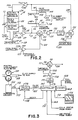
- Fig. 3 is a block diagram illustrating a portion of a second preferred embodiment of a system for dispensing fluid materials according to the invention.
- Fig. 4 is a flow chart illustrating the operation of the embodiment of Fig. 3.
- FIG. 1 a preferred embodiment of a dispensing gun 10 constructed according to the invention is shown.
- Gun 10 includes a C-shaped frame 11 having a mounting plate 12 adapted to be secured to the tool mounting face 13 of a robot arm by means of one or more cap screws 14 and alignment pins 15.
- Frame 10 is preferably constructed of a rigid light weight material such as aluminum alloy and further includes, extending outwardly from mounting plate 12, an upper portion 16, and an opposed lower portion 17.
- the upper portion 16 of frame 11 carries a servo actuator 20 which may consist of any of a number of types of compact, light weight linear actuators offering rapid response.
- actuator 20 comprises a double-acting air cylinder 22 having a piston rod 23 whose degree of extension is controlled by an electrically actuated pneumatic servovalve 24 disposed atop air cylinder 22.
- the lower portion 17 of frame 11 carries a metering valve assembly 26 having a needle valve 27 located between a fluid inlet 28 and a dispensing nozzle 29 which includes a nozzle end 30 having an outlet 31.
- needle valve 27 is located as close to nozzle 29 as practical and includes a valve stem 32 having a generally conical end 33 and a valve seat 34.
- Valve stem 32 is connected to piston rod 23 so that the position of its conical end 33 relative to valve seat 34 and hence, the flow rate of fluid discharged from nozzle 29 is controlled in accordance with the electrical input of electro-pneumatic servovalve 24.
- a transducer 36 located just downstream of needle valve 27 generates an electrical signal 37 correlated to the rate of flow of fluid discharged from nozzle 29.
- signal 37 is preferably used as a feedback signal to control the rate of flow of fluid dispensed from nozzle 29 in accordance with a desired driving signal.
- the driving signal can vary with the relative speed between nozzle 29 and the workpiece 39 to accurately control the amount of fluid per unit length contained in the bead deposited on the surface of the workpiece 39.
- Linear actuator 20 may incorporate any of a number of suitable types of fast responding electrically actuated servovalves including jet-pipe, nozzle and flapper or spool types. The details of the construction of actuator 20 are within the purview of those skilled in the art, and accordingly, do not constitute the claimed invention.
- actuator 20 comprises a jet-pipe electro-pneumatic servovalve 24 which operates a double-acting air cylinder 22.
- Servovalve 24 includes a housing 42 which supports a threaded, electrical connector 43 secured thereto by screws 44. Wired to connector 43 by way of leads 45 are a pair of series-connected coils 46 surrounding opposing ends 49 of an armature 50 which is mounted to pivot about pivot point 51.
- a hollow, inverted U-shaped jet pipe 52 has one leg connectable to a regulated air supply of about 100 PSI nominal pressure through a threaded inlet 53 in air cylinder 22 by way of filter 54.
- the opposite leg of jet-pipe 52 is secured near its center to armature 50 so that when armature 50 is pivoted clockwise by energizing coils 46 in one polarity, the flow emanating from jet pipe 52 is diverted toward a first port 60.
- coils 46 are energized in the opposite polarity, armature 50 pivots counter-clockwise to direct the flow from jet pipe 52 toward a second port 61 of air cylinder 22.
- the degree of the deflection of jet pipe 52 and hence, the pressure in ports 60 and 61 is proportional to the magnitude of the current flowing in coils 46.
- Armature 50 is spring centered and magnetically biased such that when coils 46 are in a de-energized state, jet pipe 52 is centered in a neutral position as shown so that the pressures in ports 60 and 61 tend to be equally balanced.
- Magnetic bias is provided by a pair of permanent magnets 63 each of which communicate with the armature field by way of a flux across air gaps 65. This flux is conducted to gaps 65 by way of four magnetically permeable members 66 arranged as shown.
- Double acting air cylinder 22 includes an aluminum alloy cylinder body 70, the end of which is received in a hole 71 in the upper portion 16 of frame 11.
- a flange 72 is used to secure the body 70 of air cylinder 22 to the upper portion 16 of frame 11 using cap screws 73.
- Cylinder body 70 includes first and second ports 60, 61, threaded air supply inlet 53 and filter 54 as well as a cylinder bore 75.
- Received within bore 75 is a piston 76 provided with a pair of seals 78 as well as piston rod 23 which extends axially from bore.
- the portion of bore 75 located above piston 76 communicates with first port 60 while the portion beneath piston 76 is connected to second port 61.
- piston 76 drives needle valve 27 depends upon the differential pressure between ports 60 and 61 which, as explained above, is determined by the deflection of jet pipe 50 due to the current flowing in coils 46.
- Piston is retained within cylinder bore 75 by a cap 80 through which passes piston rod 23.
- cap 80 is provided with a seal 81 in the area of piston rod 23 and an external O-ring seal 82 between the outer circumference of cap 80 and the surface of cylinder bore 75.
- Cap 80 is itself retained in the end of cylinder bore 75 by a snap-ring 83.
- Metering valve assembly 26 includes a rigid, non-resilient valve body 85 constructed as shown in Fig. 1 preferably of metal.
- the lower end of valve body 85 includes a passage 84 whose lower end is threaded to accept the flow restricting nozzle 29 of a desired configuration having a discharge outlet 31.
- Passage 84 is intersected by one or more radial threaded holes, one of which receives transducer 36 and the others of which are sealed by means of plugs 90.
- valve body 85 Located immediately upstream of passage 84 and as closely adjacent thereto as practicable, valve body 85 houses needle valve 27.
- both valve stem 32 and valve seat 34 are preferably fabricated of a hard material such as sintered tungsten carbide.
- a fluid supply inlet 28 enters valve body 85 upstream of needle valve 27. Inlet 28 is threaded so that a hose can be attached to supply under pressure the fluid material to be dispensed.
- Valve body 85 threads onto the lower end of a bonnet 97 and is sealed with respect thereto by means of an O-ring seal 98.
- Bonnet 97 includes an internal packing gland 99 which holds a plurality of annular PTFE packing seals 100. Seals 100 are retained in sealing but nonbinding compression about valve stem 32 by means of any adjustable gland nut 101.
- bonnet 97 is threadably received by the extending lower portion 17 of frame 11 and secured thereto at a desired angular orientation by means of a locknut 102.
- Metering valve assembly 26 is connected to actuator 20 by means of a coupling 105 which is fixedly attached to the upper end of valve stem 32 and threaded onto the lower end of piston rod 23 and held in place by a second locknut 106.
- Transducer 36 may comprise any suitable transducer capable of generating a signal 37 indicative of the rate of flow of the fluid dispensed from nozzle 30.
- transducer 36 is a strain gauge pressure transducer operably disposed to sense the instantaneous fluid pressure at a location inside passage 84 immediately downstream of needle valve 27.
- One pressure transducer suitable for this purpose is model A205 manufactured by Sensotec of Columbus, Ohio. The flow of a viscous newtonian fluid at low Reynolds numbers is substantially linearly proportional to the pressure drop across a nozzle or tubular restrictor placed in the flow path. It can be appreciated that a pressure transducer 36 located as described will sense the pressure drop across nozzle 29.
- transducer 36 generates a pressure signal 37 which represents the instantaneous rate of flow from outlet 31.
- pressure transducer 37 due to the proximity of needle valve 27 this flow is closely correlated to the flow through needle valve 27. Since flow rate is sensed by pressure transducer 37 and controlled by needle valve 27 both in close proximity to nozzle 29, precise control over flow rate, and hence, the amount of fluid per unity length deposited by gun 10 on workpiece 39 can be achieved by connecting dispensing gun 10 to form a fast responding closed-loop servo control system as described now with particular reference to Fig. 2.
- Dispensing gun 10 is carried by the tool mounting surface 13 of a robot having a controller (not shown) programmed to guide nozzle 29 over the surface of a workpiece to dispense a bead of fluid thereon in a desired pattern.
- the metering valve assembly 26 of gun 10 communicates at its fluid inlet 28 with a continuous pressurized supply of fluid.
- Transducer 36 continuously senses the pressure drop across nozzle 29 to generate a pressure signal 37 correlated to the rate of flow of fluid discharged from the outlet 31 of nozzle end 30.
- Signal 37 is received and amplified by a preamp 110 which generates an output signal 111 appearing at the minus input 112 of a summing junction 113 as well as at a first input 114 of a comparator 115 whose second input 116 receives a fixed, selectable voltage reference, VREF1 and whose output 117 generates a digital PRESSURE OVERRANGE signal 118 which is received by the robot controller. If the magnitude of output signal 111 exceeds VREF1, digital PRESSURE OVERRANGE signal assumes a logical 1 value. This can occur for example if needle valve 27 opens too far. In such event, the robot controller can be programmed to present a fault indication, shut down the system or take other appropriate action.
- Summing junction 113 also includes a plus input 119 which receives a driving signal 122.
- Error signal 130 is received by an amplifier 131 whose gain is adjusted for optimum system stiffness.
- the output signal 132 from amplifier 131 is received by a lead/lag compensation network 134 designed and adjusted according to standard control technique to stabilize closed-loop system response and maximize response speed with minimum overshoot.
- a second summing junction 135 then adds a dither signal 136 from a dither generator 137 to the output signal 138 of lead/lag network 134.
- Dither signal 136 is an A.C. signal whose magnitude preferably several percent of the fullscale value of signal 138. Dither signal 136 improves system resolution by overcoming static fraction effects.
- Dither signal 136 accomplishes this by causing air cylinder 22 to oscillate very slightly during system operation, as is commonly practiced in the art.
- Summing junction 135 provides an analog voltage signal 139 whose magnitude and polarity is determined by the algebraic sum of signal 138 and dither signal 136.
- Signal 139 is received by a current driver 140 as well as by the first input 141 of a comparator 142 whose second input 143 receives a fixed, selectable voltage reference, VREF2 and whose output 144 generates a digital VALVE OVERRANGE SIGNAL 145. In the event the magnitude of signal 139 exceeds VREF2, digital VALVE OVERRANGE signal assumes a logical 1 state.
- VALVE OVERRANGE signal 145 is directed to the robot controller which may be programmed to generate a fault indication, shut the system down or otherwise initiate corrective action.
- Current driver 140 generates an analog control current signal 146 which is applied to the coils 46 of servovalve 24. This causes jet pipe 52 to be diverted toward first port 60 or second port 61, depending on the magnitude and direction of control current signal 146, to move the piston 76 of air cylinder 22 either downward or upward, respectively. Downward movement of piston 76 tends to close needle valve 27 of metering valve assembly 26 thereby reducing the flow of fluid while upward movement of piston 76 tends to open needle valve 27 thereby increasing the flow of fluid.
- the system functions as a closed loop servo system responsive to the pressure drop across nozzle 29 as sensed by pressure transducer 36. With needle valve 27 initially closed, no flow occurs and the pressure drop across nozzle 29 is zero. Assuming toolspeed signal 128 is less than the threshold voltage associated with amplifier 127, amplifier 127 generates a driving signal 122 of the proper polarity and of sufficient magnitude to generate a control current 146 to deflect jet pipe the embodiment of Fig. 2, driving signal 122 is generated by an amplifier 127 in accordance with a toolspeed signal 128 from the robot. Toolspeed signal 128 is an analog voltage signal available from the robot controller which varies according to the speed of travel of gun 10 relative to workpiece 39.
- the gain of signal 128 can be adjusted by way of a toolspeed multiplier selected to provide a desired flow rate as a function of speed of travel.
- Amplifier 127 is an operational amplifier whose gain is selected to properly scale toolspeed signal 128 so that driving voltage 122 will be within a range compatible with the rest of the circuit.
- Amplifier 127 is preferably connected as a precision limiter such that for inputs between zero volts and an adjustable threshold voltage, the voltage of driving signal executes a decisive step in a direction proper to close needle valve 27.
- the threshold voltage would be adjusted so that when toolspeed signal 128 is about 50 mV or less, needle valve 27 is driven positively closed.
- Summing junction 113 produces an analog error signal 130 whose magnitude and polarity is equal to the algebraic difference between the output signal 111 of 52 toward first port 60. This holds piston 76 down so that needle valve 27 is held closed under force thereby preventing leakage. This condition is maintained until toolspeed signal 128 rises above the threshold voltage of amplifier 127 indicating that flow should commence. When this occurs, driving signal reverses polarity. Since there is initially no flow, pressure signal 137 is at its zero value.
- an error signal 130 whose magnitude is determined by the difference between pressure signal 37 and driving signal 122 will cause a control current 146 to be applied to coils 46 in such a polarity as to cause jet pipe 52 to deflect toward second port 61.
- piston 76 moves upward causing needle valve 27 to open by lifting the conical end of valve stem 32 away from valve seat 34.
- control current 146 both decrease and jet pipe 52 moves toward its null position.
- jet pipe 52 causes needle valve 52 to remain open by an amount just sufficient to maintain the pressure drop across nozzle 29 at that value.
- the flow characteristics of the fluid supplied to dispensing gun 10 may be subject to change over time.
- the viscosity of the fluid can vary with changes in temperature as the drum sits in a warm production area after having been moved from a cold warehouse. Viscosity may also vary from one drum of fluid to the next or from the top of a given drum to the bottom. Without some means for compensating for such changes, the amount of material dispensed onto a workpiece 39 would be subject to undesirable variations. Also, when dispensing non-newtonian fluids, the overall instantaneous viscosity of the fluid varies with shear rate in a non-linear fashion.
- Fig. 3 illustrates a second preferred embodiment of the invention which is similar to the embodiment described above except for the manner in which driving signal 122 is generated.
- the system of Fig. 2 is modified by adding a positive displacement flow meter 150 to the fluid supply line connected to the inlet 28 of dispensing gun 10. While it is desirable to locate flow meter 150 as close to gun 10 as possible it is not required to be mounted with the gun 10 on the robot arm.
- Flow meter 150 includes an incremental encoder 152 which produces an electrical output signal 153 comprising a series of pulses 155. Each pulse 155 represents a predetermined volume of fluid.
- Signal 153 is input to a pulse counter 156 which counts pulses 155 and is resettable to zero by a reset signal 158 which is generated by a microprocessor based controller 160 which, if desired may be part of the robot controller (not shown). However, to provide maximum system frequency response, controller 160 should run at high speed and is preferably dedicated principally to performing the operations described below.
- controller 160 includes all necessary program and data memory as well as an analog to digital converter (A/D) 163 which receives the toolspeed signal 128 from the robot controller.
- Pulse counter 156 outputs its pulse count 165 to controller 160. Controller 160 also receives from the robot controller (not shown), a digital cycle status signal 168 and a digital job status signal 170.
- Cycle status signal assumes a logical 1 value whenever dispensing gun 10 should be operating.
- Job status signal 170 assumes a logical 1 valve when a production run is at an end.
- Controller 160 also communicates by way of an interface 172 with an input/output device 175 such as a keyboard terminal from which control commands and setpoint data are entered.
- Controller 160 also communicates by way of an output 176 with a digital to analog D/A converter 177 which generates an analog signal 178.
- Signal 178 is received by amplifier 127 which operates as described above with reference to Fig. 2.
- Amplifier 127 in turn generates driving signal 122 which is applied to the plus input 119 of summing junction 113 as described above to generate error signal 130.
- the manner in which driving signal 122 is derived may be further understood with additional reference now to Fig. 4 which illustrates the software program stored in controller 160 responsible for outputting the required data to D/A converter 177.
- the program begins running by clearing all data memory and initializing all variables including a setpoint representing a desired total volume of fluid to be applied to a single workpiece 39.
- An appropriate set of pre-programmed flow linearizing factors (FLFs) are also initialized at this point.
- FLFs are constants which represent factors by which toolspeed signal 128 must be multiplied in order to linearize system flow response such that when a given percentage of the full scale value of toolspeed signal 128 is applied to summing junction 113, the needle valve 27 of metering valve assembly 26 is positioned so that the same percentage of the full scale flow of fluid is discharged from nozzle outlet 31.
- FLF's are determined empirically from a measured curve of actual flow from outlet 31 of nozzle 30 versus voltage applied at input 119 of summing junction 113. Since the actual flow curve may vary depending on the geometry of needle valve 27 and nozzle 29 including nozzle end 30 as well as the flow characteristics of the particular type of fluid being dispensed and the supply pressure, the program loads a series of FLF's appropriate to account for a particular set of these conditions.
- the program also sets a flow compensation factor (FCF) to an arbitrarily selected initial value.
- FCF is a variable which compensates for changes in the flow characteristics which occur over time such as changes in intrinsic viscosity due to changes in temperature or other factors as discussed earlier.
- the FCF is recomputed once each job cycle that is, once per dispensing operation on a given workpiece 39.
- the FCF is defined as a factor by which the linearized toolspeed signal must be multiplied so that the total volume of fluid dispensed onto a workpiece 39 is substantially equal to the selected setpoint. Deviation from setpoint cannot be determined at the beginning of the first job cycle because there is no basis for comparison. Accordingly, FCF is preferably initialized at unity. The manner in which FCF is recomputed will be described below.
- the program resets pulse counter 156 to zero by outputting an appropriate reset signal 158 from controller 160 to counter 158.
- the program causes controller 160 to read the total pulse count 165.
- the value of pulse count 165 represents the total volume of fluid dispensed during the previous job cycle. If pulse count is not zero, as will be the case except prior to the first job cycle, the program recomputes the flow compensation factor FCF as a quotient whose dividend is equal to the setpoint and whose divisor is equal to total pulse count 165. After the FCF is recomputed counter 156 is again reset in the manner described above. If pulse count 165 is equal to zero, as it will be at the beginning of the first job cycle, the FCF remains at its initialized valve.
- the program enters a loop in which it waits for the robot controller signal that a job cycle is in progress.
- the program continuously reads cycle status signal 168 and tests to determine whether it has assumed a logical 1 value. If not, the program stays in the loop.
- the program directs controller 160 to read the digital value 180 representing the magnitude of toolspeed signal 128 from the output of A/D converter- 163. Based on the magnitude of the digital value, the program selects from a look-up table the corresponding flow linearizing factor FLF from the set of FLF values loaded during initialization.
- Digital value 180 is then multiplied by the selected FLF value to yield a linearized toolspeed value 181.
- the program next causes the linearized toolspeed value 181 to be multiplied by the flow compensation factor FCF to yield a corrected digital value 182 which is then output to D/A converter 177 whose output 178 is fed to amplifier 127 to generate driving signal 122.
- cycle status signal 168 the program again reads cycle status signal 168 to determine whether dispensing should continue. If not, job status signal 168 will not be a logical 1 value, indicating the present cycle has ended. In that case the program causes controller 160 to read job status signal 170 emanating from the robot controller. If job status signal 170 is not a logical 1 value, this indicates that the last workpiece 39 in a given production lot has been finished and the program is stopped. If the production run is not complete, job status signal 170 will remain at a logical 1 value and the program will loop back to the point at which pulse count 165 is read. Although the program described recomputes a flow compensation factor once per job cycle, it should be noted that such periodic adjustments can be made more or less frequently depending on how rapidly the flow characteristics of the dispensed fluid can be expected to undergo significant change.
- Dispensing gun 10 can be directed by any desired means including manually the invention is particularly well adapted for use with robots. Dispensing gun 10 is light weight, compact and easy to maintain. Further, the dispensing systems of the invention provide for automatic flow rate adjustment in accordance with the relative speed between the dispensing gun 10 on the robot arm and the workpiece.
- the invention permits close control over the volume per unit length of the dispensed bead of fluid even during rapid acceleration and deceleration as normally occurs as the robot arm changes its direction of movement.
- the invention also provides means for periodically compensating for perturbations in the flow characteristic of the fluid being dispensed to insure that the volume of fluid dispensed always conforms closely with a desired setpoint. be made more or less frequently depending on how rapidly the flow characteristics of the dispensed fluid can be expected to undergo significant change.
- Dispensing gun 10 can be directed by any desired means including manually the invention is particularly well adapted for use with robots. Dispensing gun 10 is light weight, compact and easy to maintain. Further, the dispensing systems of the invention provide for automatic flow rate adjustment in accordance with the relative speed between the dispensing gun 10 on the robot arm and the workpiece.
- the invention permits close control over the volume per unit length of the dispensed bead of fluid even during rapid acceleration and deceleration as normally occurs as the robot arm changes its direction of movement.
- the invention also provides means for periodically compensating for perturbations in the flow characteristic of the fluid being dispensed to insure that the volume of fluid dispensed always conforms closely with a desired setpoint.
Abstract
measuring the volume of fluid delivered to said metering valve (26) during at least one said interval;
calculating a flow correction factor correlated to the difference between said measured volume and said setpoint; and
multiplying the setpoint by said flow correction factor to yield a compensated setpoint.
Description
- The present invention relates to a method for dispensing viscous fluid materials such as lubricants, sealants and adhesives onto a workpiece at a controlled rate of a flow which can be adjusted to compensate for changes in the relative speed between the dispenser and the workpiece. When dispensing viscous fluids such as certain lubricants, adhesives sealants and the like, it is often necessary to apply the material to the surface of a workpiece in a bead containing a desired amount of material per unit length. In high production processes or where the bead of material must be positioned with accuracy, robot arms are often used to apply the material by rapidly guiding a dispensing nozzle in a programmed pattern over the surface of the workpiece. Depending on the application, the fluid being dispensed may either be projected some distance from the nozzle in a high velocity stream or extruded from the nozzle at lower velocity with the nozzle located closer to the workpiece. In either case, the amount of material applied per unit of lineal distance along the head will vary according to both the flow rate of material discharged from the dispensing nozzle and the speed of the nozzle with respect to the workpiece.
- For example, in the automotive industry it is necessary to apply a uniform bead of sealant around the periphery of the inside surface of automobile doors before joining the inside panel to the door. Along long, straight portions of the pattern, a robot arm can move the nozzle quickly. However, where the desired bead pattern changes direction abruptly, such as around the corners of a door panel, the robot arm must be slowed down to achieve a required bead positioning accuracy. It can be appreciated that if the flow rate of the dispensed fluid material is held fixed, the amount of material in the applied bead wall increase as the robot arm is decelerated to negotiate changes in direction and will decrease as the robot arm is accelerated.
- In the prior art, one attempt to deal with this problem has been to apply a toolspeed signal emanating from the robot controller to a voltage-controlled D.C. motor drive to control the speed of a ball screw mechanism driving the plunger of a shot pump filled with fluid. The shot pump is connected to the dispensing nozzle on the robot arm by way of a length of flexible hose. The toolspeed signal applied to the D.C. drive varies with the speed of the nozzle relative to the workpiece. As the rate of travel of the shot pump plunger changes, so too does the flow rate from the nozzle. Thus, the rate at which fluid is dispensed is controlled in open-loop fashion according to the speed of the nozzle.
- Such a system suffers a number of deficiencies. First, it is inherently slow to respond Therefore, only limited control of bead size is possible. In addition to the delays associated with the response of the D.C. drive and mechanical system driving the plunger, the flexible hose connected between the shot pump and the nozzle carried by the robot arm introduces significant response lag into the system. With a hose only 10 feet long, and depending on supply pressure and the characteristics of the fluid being dispensed, it may take a second or more for a change in pressure at the shot pump to be reflected in a corresponding change in flow at the nozzle. Thus, very precise control of bead size is difficult particularly during rapid changes in the speed of the robot arm. In addition to these performance limitations, such systems have other practical disadvantages. The shot pump itself should be capable of holding at least as much material as required to be applied to an entire workpiece. Accordingly, the pump and its associated mechanical drive are too bulky and massive to be mounted on the robot arm with the dispensing nozzle. The mechanical components and D.C. drive controls together may weigh up to several hundred pounds. Further, such a system is expensive to maintain and occupies a significant amount of production floor space.
- Another type of system known in the prior art uses a more compact dispenser having a motor driven metering valve which receives a continuous supply of material by way of a flexible hose. The dispenser is mounted on the robot arm and includes a servomotor or stepper motor which controls the metering valve to adjust the flow in accordance with the speed of the dispensing nozzle as indicated by a toolspeed signal emanating from the robot. Closed-loop control of flow is effected by a feedback signal indicative of material flow deriving, at some point in the system remote from the dispensing nozzle. This feedback signal may be derived by sensing the displacement of the supply pump using an LVDT or potentiometer connected to the crosshead of the pump or by using a positive displacement flow-meter connected in line with the flexible hose which feeds the dispenser. In addition to this main control loop, such a system can incorporate a pressure sensor at the nozzle of the dispenser to shut off under specified conditions as described in European Patent Application No. 85-104,127.7. This reference discloses the use of one or pressure sensors located in the wall of the dispensing nozzle to derive a pair of signals, one of which is used to indicate the presence of bubbles, the other of which indicates the flow of the liquid. The patent states that the latter signal can be derived for example from a pair of contacts connected to an elastic pressure-transmitting element which keeps the contacts closed as long as the pressure at the nozzle exceeds a certain value. In the event a clog develops in the flow channel, the flow signal can be used to initiate a shutdown of the system or provide an indication. Similar action can be taken should a bubble be sensed at the nozzle.
- This type of system also has significant performance limitations. Even though the material being dispensed is metered by a dispenser mounted on the robot arm rather than from a remote metering device such as the shot pump system described above, the response time of the system is still relatively slow. As a consequence, the ability of the system to control bead size is limited, especially during rapid changes in the relative speed between the dispenser nozzle and the workpiece.
- It is an objective of the invention to provide a method of compensating for changes in the flow characteristics of a fluid being dispensed from a nozzle under the control of a metering valve in order to maintain the volume of fluid dispensed over a predetermined interval at a desired setpoint.
- It is a further objective of the invention to provide a method for periodically correcting for changes in the intrinsic viscosity of the fluid being dispensed in order to dispense a desired amount of material to each workpiece in a lot.
- In order to accomplish the above objects, according to the invention, there is provided an apparatus for dispensing fluid material onto a workpiece, said apparatus comprising a fluid inlet connectable to a pressurized supply of fluid, a valve having a valve inlet and a valve outlet, said valve communicating with said fluid inlet, a dispensing nozzle disposed downstream of said valve, said nozzle having a nozzle inlet and a nozzle outlet, a sensor for sensing a parameter other than the position of a flow restricting element, said parameter being correlated to the rate of flow of the fluid discharged from said nozzle outlet and generating a corresponding flow rate signal, and an actuator connected to said valve, said actuator being responsive to said flow rate signal to control the rate of flow of fluid discharged from said nozzle outlet when said valve is at least partially open, characterized in that said valve is operable to substantially infinitely variably modulate flow of the fluid when said valve is at least partially open and to positively cut off flow when said valve is closed, said nozzle inlet is positioned in sufficiently close proximity to said valve outlet that very little fluid pressure drop occurs in a region of flow including said valve outlet and said nozzle inlet in relation to the pressure drop across said nozzle when said valve is at least partially open, said sensor operably communicates with said region in close proximity to both said valve outlet and said nozzle inlet, and the flow of fluid is modulated by said valve and sensed in close proximity to said nozzle inlet within said region of flow to provide said apparatus with enhanced response characteristics.
- Further advantages embodiments of the method are defined in the
subclaims 2 to 10. - These and other advantages will be readily apparent from the following detailed description of a preferred embodiment of the invention and from the accompanying drawings wherein like reference numerals designate like items.
- Fig. 1 is a schematic cross sectional view illustrating a preferred embodiment of a dispensing apparatus constructed according to the invention.
- Fig. 2 is a block diagram illustrating a preferred embodiment of a system for dispensing fluid materials according to the invention.
- Fig. 3 is a block diagram illustrating a portion of a second preferred embodiment of a system for dispensing fluid materials according to the invention.
- Fig. 4 is a flow chart illustrating the operation of the embodiment of Fig. 3.
- Referring now to Fig. 1 a preferred embodiment of a dispensing
gun 10 constructed according to the invention is shown.Gun 10 includes a C-shaped frame 11 having amounting plate 12 adapted to be secured to thetool mounting face 13 of a robot arm by means of one ormore cap screws 14 and alignment pins 15.Frame 10 is preferably constructed of a rigid light weight material such as aluminum alloy and further includes, extending outwardly frommounting plate 12, anupper portion 16, and an opposedlower portion 17. Theupper portion 16 of frame 11 carries a servo actuator 20 which may consist of any of a number of types of compact, light weight linear actuators offering rapid response. Preferably, actuator 20 comprises a double-actingair cylinder 22 having apiston rod 23 whose degree of extension is controlled by an electrically actuatedpneumatic servovalve 24 disposed atopair cylinder 22. Thelower portion 17 of frame 11 carries ametering valve assembly 26 having aneedle valve 27 located between afluid inlet 28 and a dispensingnozzle 29 which includes anozzle end 30 having anoutlet 31. For best control,needle valve 27 is located as close tonozzle 29 as practical and includes avalve stem 32 having a generallyconical end 33 and avalve seat 34.Valve stem 32 is connected topiston rod 23 so that the position of itsconical end 33 relative tovalve seat 34 and hence, the flow rate of fluid discharged fromnozzle 29 is controlled in accordance with the electrical input of electro-pneumatic servovalve 24. Atransducer 36 located just downstream ofneedle valve 27 generates anelectrical signal 37 correlated to the rate of flow of fluid discharged fromnozzle 29. As will be described in further detail below,signal 37 is preferably used as a feedback signal to control the rate of flow of fluid dispensed fromnozzle 29 in accordance with a desired driving signal. In robotic applications, the driving signal can vary with the relative speed betweennozzle 29 and theworkpiece 39 to accurately control the amount of fluid per unit length contained in the bead deposited on the surface of theworkpiece 39. - Linear actuator 20 may incorporate any of a number of suitable types of fast responding electrically actuated servovalves including jet-pipe, nozzle and flapper or spool types. The details of the construction of actuator 20 are within the purview of those skilled in the art, and accordingly, do not constitute the claimed invention. In the preferred embodiment illustrated in Fig. 1, actuator 20 comprises a jet-pipe electro-
pneumatic servovalve 24 which operates a double-actingair cylinder 22. Servovalve 24 includes a housing 42 which supports a threaded,electrical connector 43 secured thereto byscrews 44. Wired toconnector 43 by way ofleads 45 are a pair of series-connectedcoils 46 surroundingopposing ends 49 of anarmature 50 which is mounted to pivot about pivot point 51. A hollow, inverted U-shapedjet pipe 52 has one leg connectable to a regulated air supply of about 100 PSI nominal pressure through a threadedinlet 53 inair cylinder 22 by way offilter 54. The opposite leg of jet-pipe 52 is secured near its center toarmature 50 so that whenarmature 50 is pivoted clockwise by energizingcoils 46 in one polarity, the flow emanating fromjet pipe 52 is diverted toward afirst port 60. Similarly, whencoils 46 are energized in the opposite polarity,armature 50 pivots counter-clockwise to direct the flow fromjet pipe 52 toward asecond port 61 ofair cylinder 22. In either polarity, the degree of the deflection ofjet pipe 52 and hence, the pressure inports coils 46.Armature 50 is spring centered and magnetically biased such that when coils 46 are in a de-energized state,jet pipe 52 is centered in a neutral position as shown so that the pressures inports permanent magnets 63 each of which communicate with the armature field by way of a flux acrossair gaps 65. This flux is conducted togaps 65 by way of four magneticallypermeable members 66 arranged as shown. - Double acting
air cylinder 22 includes an aluminumalloy cylinder body 70, the end of which is received in ahole 71 in theupper portion 16 of frame 11. Aflange 72 is used to secure thebody 70 ofair cylinder 22 to theupper portion 16 of frame 11 using cap screws 73.Cylinder body 70 includes first andsecond ports air supply inlet 53 andfilter 54 as well as acylinder bore 75. Received withinbore 75 is apiston 76 provided with a pair ofseals 78 as well aspiston rod 23 which extends axially from bore. The portion ofbore 75 located abovepiston 76 communicates withfirst port 60 while the portion beneathpiston 76 is connected tosecond port 61. The force with whichpiston 76drives needle valve 27 depends upon the differential pressure betweenports jet pipe 50 due to the current flowing in coils 46. Piston is retained within cylinder bore 75 by acap 80 through which passespiston rod 23. To preventair leakage cap 80 is provided with aseal 81 in the area ofpiston rod 23 and an external O-ring seal 82 between the outer circumference ofcap 80 and the surface of cylinder bore 75.Cap 80 is itself retained in the end of cylinder bore 75 by a snap-ring 83. -
Metering valve assembly 26 includes a rigid,non-resilient valve body 85 constructed as shown in Fig. 1 preferably of metal. The lower end ofvalve body 85 includes apassage 84 whose lower end is threaded to accept theflow restricting nozzle 29 of a desired configuration having adischarge outlet 31.Passage 84 is intersected by one or more radial threaded holes, one of which receivestransducer 36 and the others of which are sealed by means ofplugs 90. Located immediately upstream ofpassage 84 and as closely adjacent thereto as practicable,valve body 85 houses needlevalve 27. For long life, bothvalve stem 32 andvalve seat 34 are preferably fabricated of a hard material such as sintered tungsten carbide. Afluid supply inlet 28 entersvalve body 85 upstream ofneedle valve 27.Inlet 28 is threaded so that a hose can be attached to supply under pressure the fluid material to be dispensed. -
Valve body 85 threads onto the lower end of abonnet 97 and is sealed with respect thereto by means of an O-ring seal 98.Bonnet 97 includes an internal packing gland 99 which holds a plurality of annular PTFE packing seals 100.Seals 100 are retained in sealing but nonbinding compression about valve stem 32 by means of anyadjustable gland nut 101. To attachmetering valve assembly 26 to frame 11,bonnet 97 is threadably received by the extendinglower portion 17 of frame 11 and secured thereto at a desired angular orientation by means of alocknut 102.Metering valve assembly 26 is connected to actuator 20 by means of acoupling 105 which is fixedly attached to the upper end ofvalve stem 32 and threaded onto the lower end ofpiston rod 23 and held in place by asecond locknut 106. -
Transducer 36 may comprise any suitable transducer capable of generating asignal 37 indicative of the rate of flow of the fluid dispensed fromnozzle 30. Preferably,transducer 36 is a strain gauge pressure transducer operably disposed to sense the instantaneous fluid pressure at a location insidepassage 84 immediately downstream ofneedle valve 27. One pressure transducer suitable for this purpose is model A205 manufactured by Sensotec of Columbus, Ohio. The flow of a viscous newtonian fluid at low Reynolds numbers is substantially linearly proportional to the pressure drop across a nozzle or tubular restrictor placed in the flow path. It can be appreciated that apressure transducer 36 located as described will sense the pressure drop acrossnozzle 29. This is so because theoutlet 31 ofnozzle 29 is at atmospheric pressure and there is very little pressure drop acrosspassage 84 in relation to the pressure drop acrossnozzle 30. Thus,transducer 36 generates apressure signal 37 which represents the instantaneous rate of flow fromoutlet 31. As previously noted, due to the proximity ofneedle valve 27 this flow is closely correlated to the flow throughneedle valve 27. Since flow rate is sensed bypressure transducer 37 and controlled byneedle valve 27 both in close proximity tonozzle 29, precise control over flow rate, and hence, the amount of fluid per unity length deposited bygun 10 onworkpiece 39 can be achieved by connecting dispensinggun 10 to form a fast responding closed-loop servo control system as described now with particular reference to Fig. 2. - Dispensing
gun 10 is carried by thetool mounting surface 13 of a robot having a controller (not shown) programmed to guidenozzle 29 over the surface of a workpiece to dispense a bead of fluid thereon in a desired pattern. Themetering valve assembly 26 ofgun 10 communicates at itsfluid inlet 28 with a continuous pressurized supply of fluid.Transducer 36 continuously senses the pressure drop acrossnozzle 29 to generate apressure signal 37 correlated to the rate of flow of fluid discharged from theoutlet 31 ofnozzle end 30.Signal 37 is received and amplified by apreamp 110 which generates anoutput signal 111 appearing at theminus input 112 of a summingjunction 113 as well as at afirst input 114 of acomparator 115 whosesecond input 116 receives a fixed, selectable voltage reference, VREF1 and whoseoutput 117 generates a digitalPRESSURE OVERRANGE signal 118 which is received by the robot controller. If the magnitude ofoutput signal 111 exceeds VREF1, digital PRESSURE OVERRANGE signal assumes a logical 1 value. This can occur for example ifneedle valve 27 opens too far. In such event, the robot controller can be programmed to present a fault indication, shut down the system or take other appropriate action. Summingjunction 113 also includes aplus input 119 which receives adriving signal 122. Inpreamp 110 and drivingsignal 122.Error signal 130 is received by anamplifier 131 whose gain is adjusted for optimum system stiffness. Theoutput signal 132 fromamplifier 131 is received by a lead/lag compensation network 134 designed and adjusted according to standard control technique to stabilize closed-loop system response and maximize response speed with minimum overshoot. A second summingjunction 135 then adds adither signal 136 from a dither generator 137 to theoutput signal 138 of lead/lag network 134. Dither signal 136 is an A.C. signal whose magnitude preferably several percent of the fullscale value ofsignal 138. Dither signal 136 improves system resolution by overcoming static fraction effects. Dither signal 136 accomplishes this by causingair cylinder 22 to oscillate very slightly during system operation, as is commonly practiced in the art. Summingjunction 135 provides ananalog voltage signal 139 whose magnitude and polarity is determined by the algebraic sum ofsignal 138 anddither signal 136.Signal 139 is received by a current driver 140 as well as by thefirst input 141 of acomparator 142 whosesecond input 143 receives a fixed, selectable voltage reference, VREF2 and whoseoutput 144 generates a digital VALVE OVERRANGE SIGNAL 145. In the event the magnitude ofsignal 139 exceeds VREF2, digital VALVE OVERRANGE signal assumes a logical 1 state. Such a condition may arise for example if the supply of fluid to dispensinggun 10 is cutoff or if supply pressure is inadequate to meet the demand imposed by drivingsignal 122. LikePRESSURE OVERRANGE signal 118, VALVE OVERRANGE signal 145 is directed to the robot controller which may be programmed to generate a fault indication, shut the system down or otherwise initiate corrective action. - Current driver 140 generates an analog control
current signal 146 which is applied to thecoils 46 ofservovalve 24. This causesjet pipe 52 to be diverted towardfirst port 60 orsecond port 61, depending on the magnitude and direction of controlcurrent signal 146, to move thepiston 76 ofair cylinder 22 either downward or upward, respectively. Downward movement ofpiston 76 tends to closeneedle valve 27 ofmetering valve assembly 26 thereby reducing the flow of fluid while upward movement ofpiston 76 tends to openneedle valve 27 thereby increasing the flow of fluid. - In operation, the system functions as a closed loop servo system responsive to the pressure drop across
nozzle 29 as sensed bypressure transducer 36. Withneedle valve 27 initially closed, no flow occurs and the pressure drop acrossnozzle 29 is zero. Assumingtoolspeed signal 128 is less than the threshold voltage associated withamplifier 127,amplifier 127 generates adriving signal 122 of the proper polarity and of sufficient magnitude to generate a control current 146 to deflect jet pipe the embodiment of Fig. 2, drivingsignal 122 is generated by anamplifier 127 in accordance with atoolspeed signal 128 from the robot.Toolspeed signal 128 is an analog voltage signal available from the robot controller which varies according to the speed of travel ofgun 10 relative to workpiece 39. Through the robot controller, the gain ofsignal 128 can be adjusted by way of a toolspeed multiplier selected to provide a desired flow rate as a function of speed of travel.Amplifier 127 is an operational amplifier whose gain is selected to properly scaletoolspeed signal 128 so that drivingvoltage 122 will be within a range compatible with the rest of the circuit.Amplifier 127 is preferably connected as a precision limiter such that for inputs between zero volts and an adjustable threshold voltage, the voltage of driving signal executes a decisive step in a direction proper to closeneedle valve 27. Typically, the threshold voltage would be adjusted so that whentoolspeed signal 128 is about 50 mV or less,needle valve 27 is driven positively closed. This preventsneedle valve 27 from leaking by providing a negative bias current to servovalve 24, effective to driveneedle valve 27 positively closed at times whentoolspeed signal 128 is not present or quite small. Summingjunction 113 produces ananalog error signal 130 whose magnitude and polarity is equal to the algebraic difference between theoutput signal 111 of 52 towardfirst port 60. This holdspiston 76 down so thatneedle valve 27 is held closed under force thereby preventing leakage. This condition is maintained untiltoolspeed signal 128 rises above the threshold voltage ofamplifier 127 indicating that flow should commence. When this occurs, driving signal reverses polarity. Since there is initially no flow, pressure signal 137 is at its zero value. Accordingly, anerror signal 130 whose magnitude is determined by the difference betweenpressure signal 37 and drivingsignal 122 will cause a control current 146 to be applied tocoils 46 in such a polarity as to causejet pipe 52 to deflect towardsecond port 61. In response,piston 76 moves upward causingneedle valve 27 to open by lifting the conical end of valve stem 32 away fromvalve seat 34. As thepressure signal 37 generated bypressure transducer 36increases error signal 130 and control current 146 both decrease andjet pipe 52 moves toward its null position. As the pressure drop acrossnozzle 29 approaches a value corresponding to a desired flowrate jet pipe 52 causesneedle valve 52 to remain open by an amount just sufficient to maintain the pressure drop acrossnozzle 29 at that value. - In some dispensing applications, the flow characteristics of the fluid supplied to dispensing
gun 10 may be subject to change over time. For example ifgun 10 is supplied fluid from a drum, the viscosity of the fluid can vary with changes in temperature as the drum sits in a warm production area after having been moved from a cold warehouse. Viscosity may also vary from one drum of fluid to the next or from the top of a given drum to the bottom. Without some means for compensating for such changes, the amount of material dispensed onto aworkpiece 39 would be subject to undesirable variations. Also, when dispensing non-newtonian fluids, the overall instantaneous viscosity of the fluid varies with shear rate in a non-linear fashion. Thus, absent correction, shear induced by the geometry ofnozzle 29 will result in a non-linear flow rate versuspressure signal 37 flow characteristic. This in turn would render the flow rate versus appliedtoolspeed signal 128 response non-linear. According to the invention, these problems are effectively addressed by deriving drivingsignal 122 in an alternate fashion as described now with additional reference to Figs. 3 and 4. - Fig. 3 illustrates a second preferred embodiment of the invention which is similar to the embodiment described above except for the manner in which driving signal 122 is generated. As illustrated in Fig. 3, the system of Fig. 2 is modified by adding a positive
displacement flow meter 150 to the fluid supply line connected to theinlet 28 of dispensinggun 10. While it is desirable to locateflow meter 150 as close togun 10 as possible it is not required to be mounted with thegun 10 on the robot arm.Flow meter 150 includes anincremental encoder 152 which produces anelectrical output signal 153 comprising a series ofpulses 155. Eachpulse 155 represents a predetermined volume of fluid.Signal 153 is input to apulse counter 156 which countspulses 155 and is resettable to zero by areset signal 158 which is generated by a microprocessor basedcontroller 160 which, if desired may be part of the robot controller (not shown). However, to provide maximum system frequency response,controller 160 should run at high speed and is preferably dedicated principally to performing the operations described below. In addition to a microprocessor and associated hardware,controller 160 includes all necessary program and data memory as well as an analog to digital converter (A/D) 163 which receives thetoolspeed signal 128 from the robot controller.Pulse counter 156 outputs itspulse count 165 tocontroller 160.Controller 160 also receives from the robot controller (not shown), a digitalcycle status signal 168 and a digitaljob status signal 170. Cycle status signal assumes a logical 1 value whenever dispensinggun 10 should be operating.Job status signal 170 assumes a logical 1 valve when a production run is at an end.Controller 160 also communicates by way of aninterface 172 with an input/output device 175 such as a keyboard terminal from which control commands and setpoint data are entered.Controller 160 also communicates by way of anoutput 176 with a digital to analog D/A converter 177 which generates ananalog signal 178.Signal 178 is received byamplifier 127 which operates as described above with reference to Fig. 2.Amplifier 127 in turn generates drivingsignal 122 which is applied to theplus input 119 of summingjunction 113 as described above to generateerror signal 130. The manner in which driving signal 122 is derived may be further understood with additional reference now to Fig. 4 which illustrates the software program stored incontroller 160 responsible for outputting the required data to D/A converter 177. - The program begins running by clearing all data memory and initializing all variables including a setpoint representing a desired total volume of fluid to be applied to a
single workpiece 39. An appropriate set of pre-programmed flow linearizing factors (FLFs) are also initialized at this point. The FLF's are constants which represent factors by which toolspeed signal 128 must be multiplied in order to linearize system flow response such that when a given percentage of the full scale value oftoolspeed signal 128 is applied to summingjunction 113, theneedle valve 27 ofmetering valve assembly 26 is positioned so that the same percentage of the full scale flow of fluid is discharged fromnozzle outlet 31. FLF's are determined empirically from a measured curve of actual flow fromoutlet 31 ofnozzle 30 versus voltage applied atinput 119 of summingjunction 113. Since the actual flow curve may vary depending on the geometry ofneedle valve 27 andnozzle 29 includingnozzle end 30 as well as the flow characteristics of the particular type of fluid being dispensed and the supply pressure, the program loads a series of FLF's appropriate to account for a particular set of these conditions. - The program also sets a flow compensation factor (FCF) to an arbitrarily selected initial value. The FCF is a variable which compensates for changes in the flow characteristics which occur over time such as changes in intrinsic viscosity due to changes in temperature or other factors as discussed earlier. The FCF is recomputed once each job cycle that is, once per dispensing operation on a given
workpiece 39. The FCF is defined as a factor by which the linearized toolspeed signal must be multiplied so that the total volume of fluid dispensed onto aworkpiece 39 is substantially equal to the selected setpoint. Deviation from setpoint cannot be determined at the beginning of the first job cycle because there is no basis for comparison. Accordingly, FCF is preferably initialized at unity. The manner in which FCF is recomputed will be described below. - During initialization, the program resets
pulse counter 156 to zero by outputting an appropriate reset signal 158 fromcontroller 160 to counter 158. Next, the program causescontroller 160 to read thetotal pulse count 165. The value ofpulse count 165 represents the total volume of fluid dispensed during the previous job cycle. If pulse count is not zero, as will be the case except prior to the first job cycle, the program recomputes the flow compensation factor FCF as a quotient whose dividend is equal to the setpoint and whose divisor is equal tototal pulse count 165. After the FCF is recomputedcounter 156 is again reset in the manner described above. Ifpulse count 165 is equal to zero, as it will be at the beginning of the first job cycle, the FCF remains at its initialized valve. - Next, the program enters a loop in which it waits for the robot controller signal that a job cycle is in progress. In the wait loop, the program continuously reads
cycle status signal 168 and tests to determine whether it has assumed a logical 1 value. If not, the program stays in the loop. By changingstatus signal 168 from a logical zero value to a logical 1 value, the robot controller indicates that dispensing should commence. At that point, the program directscontroller 160 to read thedigital value 180 representing the magnitude oftoolspeed signal 128 from the output of A/D converter- 163. Based on the magnitude of the digital value, the program selects from a look-up table the corresponding flow linearizing factor FLF from the set of FLF values loaded during initialization.Digital value 180 is then multiplied by the selected FLF value to yield a linearizedtoolspeed value 181. To adjust driving signal 122 so that the actual volume of fluid to be dispensed during the job cycle conforms to the setpoint despite changes in the flow characteristics of the fluid, such as changes in viscosity, the program next causes the linearizedtoolspeed value 181 to be multiplied by the flow compensation factor FCF to yield a correcteddigital value 182 which is then output to D/A converter 177 whoseoutput 178 is fed toamplifier 127 to generate drivingsignal 122. - Next, the program again reads
cycle status signal 168 to determine whether dispensing should continue. If not,job status signal 168 will not be a logical 1 value, indicating the present cycle has ended. In that case the program causescontroller 160 to read job status signal 170 emanating from the robot controller. Ifjob status signal 170 is not a logical 1 value, this indicates that thelast workpiece 39 in a given production lot has been finished and the program is stopped. If the production run is not complete,job status signal 170 will remain at a logical 1 value and the program will loop back to the point at whichpulse count 165 is read. Although the program described recomputes a flow compensation factor once per job cycle, it should be noted that such periodic adjustments can be made more or less frequently depending on how rapidly the flow characteristics of the dispensed fluid can be expected to undergo significant change. - The advantages realized by the invention are numerous. Most notably, the dispensing systems described provide rapid and precise control of fluid flow rate. Such systems have been found to have an upper 3dB frequency response cutoff point exceeding 10 hertz.
- While the dispensing
gun 10 can be directed by any desired means including manually the invention is particularly well adapted for use with robots. Dispensinggun 10 is light weight, compact and easy to maintain. Further, the dispensing systems of the invention provide for automatic flow rate adjustment in accordance with the relative speed between the dispensinggun 10 on the robot arm and the workpiece. - Thus, the invention permits close control over the volume per unit length of the dispensed bead of fluid even during rapid acceleration and deceleration as normally occurs as the robot arm changes its direction of movement. The invention also provides means for periodically compensating for perturbations in the flow characteristic of the fluid being dispensed to insure that the volume of fluid dispensed always conforms closely with a desired setpoint. be made more or less frequently depending on how rapidly the flow characteristics of the dispensed fluid can be expected to undergo significant change.
- The advantages realized by the invention are numerous. Most notably, the dispensing systems described provide rapid and precise control of fluid flow rate. Such systems have been found to have an upper 3dB frequency response cutoff point exceeding 10 hertz.
- While the dispensing
gun 10 can be directed by any desired means including manually the invention is particularly well adapted for use with robots. Dispensinggun 10 is light weight, compact and easy to maintain. Further, the dispensing systems of the invention provide for automatic flow rate adjustment in accordance with the relative speed between the dispensinggun 10 on the robot arm and the workpiece. - Thus, the invention permits close control over the volume per unit length of the dispensed bead of fluid even during rapid acceleration and deceleration as normally occurs as the robot arm changes its direction of movement. The invention also provides means for periodically compensating for perturbations in the flow characteristic of the fluid being dispensed to insure that the volume of fluid dispensed always conforms closely with a desired setpoint.
Claims (10)
- A method of compensating for changes in the flow characteristics of a fluid being dispensed from a nozzle (29) under the control of a metering valve (26) in order to maintain the volume of fluid dispensed over a predetermined interval at a desired setpoint, said method comprising the steps of:
measuring the volume of fluid delivered to said metering valve (26) during at least one said interval;
calculating a flow correction factor correlated to the difference between said measured volume and said setpoint; and
multiplying the setpoint by said flow correction factor to yield a compensated setpoint. - The method of claim 1 further comprising the step of applying said signal correlated to said compensated setpoint to a closed-loop feedback system operative to control said metering valve (26).
- The method of claim 1 or 2 wherein said flow correction factor comprises a quotient whose dividend is said setpoint and whose divisor is said measured volume of fluid.
- The method of at least anyone of claims 1 to 3, further comprising the steps of:
delivering the fluid under pressure to said metering valve (26) located upstream of the nozzle (29), said metering valve (26) being operable to modulate the flow of fluid to the nozzle (29) in response to a control signal (146);
generating a corresponding measurement signal upon measuring the volume of fluid delivered to said metering valve (26) over said interval; and
adjusting the control signal (146) in accordance with the difference between said measurement signal and said compensated setpoint. - The method of claim 4 wherein said adjusting step comprises the steps of:
calculating a correction factor correlated to the difference between said measurement signal and said setpoint;
multiplying a driving signal (122) by said correction factor, and
generating said control signal (146) from at least said driving signal. - The method of claim 4 or 5 wherein said generating step comprises the step of algebraically combining the difference between said driving signal (122) with a signal (37, 111) correlated to the flow rate of the fluid dispensed from the nozzle (29).
- The method of at least anyone of claims 4 to 6, further comprising the step of:
generating said driving signal (122) in accordance with at least a toolspeed signal (128) of a robot for effecting relative movement between the nozzle (29) and a workpiece (39). - The step of claim 7 wherein said signal (37, 111) correlated to the flow rate of the fluid dispensed from the nozzle (29) comprises a signal representing the pressure drop across said nozzle (29).
- The method of at least anyone of claims 1 to 8 wherein said interval is a job cycle.
- The method of at least anyone of claims 1 to 9 further comprising the steps of:
locating said valve (26) and said nozzle (29) in sufficiently close proximity to one another that very little fluid pressure drop occurs between said valve (26) and said nozzle (29);
sensing at a location between said valve (26) and said nozzle (29), a parameter correlated to the rate of flow of the fluid discharged from the nozzle (29) and generating the corresponding flow rate signal (37, 111), and
generating said control signal (146) from at least said flow rate signal (37, 111) and a driving signal (122).
Applications Claiming Priority (3)
| Application Number | Priority Date | Filing Date | Title |
|---|---|---|---|
| US92494086A | 1986-10-30 | 1986-10-30 | |
| US924940 | 1986-10-30 | ||
| EP87907197A EP0329683B1 (en) | 1986-10-30 | 1987-10-08 | Apparatus and method for dispensing fluid materials |
Related Parent Applications (2)
| Application Number | Title | Priority Date | Filing Date |
|---|---|---|---|
| EP87907197.5 Division | 1987-10-08 | ||
| EP87907197A Division EP0329683B1 (en) | 1986-10-30 | 1987-10-08 | Apparatus and method for dispensing fluid materials |
Publications (3)
| Publication Number | Publication Date |
|---|---|
| EP0529686A2 true EP0529686A2 (en) | 1993-03-03 |
| EP0529686A3 EP0529686A3 (en) | 1993-05-05 |
| EP0529686B1 EP0529686B1 (en) | 1997-07-09 |
Family
ID=25450948
Family Applications (2)
| Application Number | Title | Priority Date | Filing Date |
|---|---|---|---|
| EP87907197A Expired - Lifetime EP0329683B1 (en) | 1986-10-30 | 1987-10-08 | Apparatus and method for dispensing fluid materials |
| EP92117048A Expired - Lifetime EP0529686B1 (en) | 1986-10-30 | 1987-10-08 | Method of compensating for changes in the flow characteristic of a fluid being dispensed from a nozzle |
Family Applications Before (1)
| Application Number | Title | Priority Date | Filing Date |
|---|---|---|---|
| EP87907197A Expired - Lifetime EP0329683B1 (en) | 1986-10-30 | 1987-10-08 | Apparatus and method for dispensing fluid materials |
Country Status (8)
| Country | Link |
|---|---|
| EP (2) | EP0329683B1 (en) |
| JP (2) | JP2625135B2 (en) |
| KR (1) | KR950005189B1 (en) |
| AU (2) | AU603156B2 (en) |
| CA (1) | CA1300088C (en) |
| DE (2) | DE3752087T2 (en) |
| HK (1) | HK1000943A1 (en) |
| WO (1) | WO1988003059A1 (en) |
Cited By (1)
| Publication number | Priority date | Publication date | Assignee | Title |
|---|---|---|---|---|
| EP0764896A1 (en) * | 1995-09-22 | 1997-03-26 | Graco Inc. | Volume compensating pressure regulated flow control dispensing system |
Families Citing this family (22)
| Publication number | Priority date | Publication date | Assignee | Title |
|---|---|---|---|---|
| JPH0610262Y2 (en) * | 1987-12-29 | 1994-03-16 | 四国化工機株式会社 | Hydrogen peroxide water spray device |
| EP0576498B2 (en) * | 1991-03-27 | 2000-05-17 | SCA SCHUCKER GmbH | Method and device for applying a paste |
| US5277927A (en) * | 1992-03-23 | 1994-01-11 | Nordson Corporation | Method of applying primers onto glass elements of vehicles |
| FR2716729B1 (en) * | 1994-02-25 | 1996-05-24 | Seva | Device for depositing a fluid material, corresponding installation and method for using the device. |
| DE19650781A1 (en) * | 1996-12-06 | 1998-06-10 | Itw Oberflaechentechnik Gmbh | Spray coating device |
| JPH10328605A (en) * | 1997-06-02 | 1998-12-15 | Nec Corp | Coating device |
| WO2000040346A1 (en) * | 1998-12-28 | 2000-07-13 | Musashi Engineering, Inc. | Method and device for injecting a fixed quantity of liquid |
| JP3488654B2 (en) | 1999-03-09 | 2004-01-19 | 本田技研工業株式会社 | Engine control device for hybrid vehicle |
| US6308553B1 (en) * | 1999-06-04 | 2001-10-30 | Honeywell International Inc | Self-normalizing flow sensor and method for the same |
| JP4316921B2 (en) * | 2003-04-25 | 2009-08-19 | 大日本スクリーン製造株式会社 | Substrate processing equipment |
| JP2005238177A (en) * | 2004-02-27 | 2005-09-08 | Denso Corp | Line controller |
| JP4668027B2 (en) * | 2005-10-17 | 2011-04-13 | シーケーディ株式会社 | Chemical supply system |
| EP1829619A3 (en) * | 2006-02-10 | 2009-06-24 | Baumer hhs GmbH | Pneumatic material pressure controller |
| KR100735679B1 (en) * | 2006-08-21 | 2007-07-04 | (주)예은테크 | Cylinder device allowing fulid supply to be carried out and checked automatically |
| DE102009038924B3 (en) * | 2009-08-26 | 2011-02-24 | Drei Bond Gmbh | Method for filling fluid over component surface, involves leading fluid to regulating valve through conductor, where regulating valve is led to outlet opening |
| US9296009B2 (en) * | 2012-07-13 | 2016-03-29 | Nordson Corporation | Adhesive dispensing system having metering system including variable frequency drive and closed-loop feedback control |
| JP6467132B2 (en) * | 2013-12-27 | 2019-02-06 | 蛇の目ミシン工業株式会社 | Robot, robot control method, and robot control program |
| JP6705847B2 (en) * | 2018-02-14 | 2020-06-03 | ファナック株式会社 | Robot system for performing learning control based on processing result and control method thereof |
| DE102018108915A1 (en) * | 2018-04-16 | 2019-10-17 | Atlas Copco Ias Gmbh | metering valve |
| CN109542130B (en) * | 2018-11-07 | 2021-10-08 | 广东震仪智能装备股份有限公司 | Ion shower nozzle flow control system and equipment |
| EP4043109A4 (en) | 2019-10-07 | 2023-11-08 | ThreeBond Co., Ltd. | Ejection device, transfer member, and circulation control method |
| CN111045458B (en) * | 2019-12-25 | 2021-07-20 | 华南理工大学 | non-Newtonian fluid micro-coating system and control method |
Citations (2)
| Publication number | Priority date | Publication date | Assignee | Title |
|---|---|---|---|---|
| FR2077892A1 (en) * | 1970-02-23 | 1971-11-05 | Penet Pierre | Improvements to the calibration of flow measuring devices or the like |
| EP0192166A2 (en) * | 1985-02-22 | 1986-08-27 | Josef Schucker | Flow regulation or control method for a viscous fluid dispensed as a seam |
Family Cites Families (10)
| Publication number | Priority date | Publication date | Assignee | Title |
|---|---|---|---|---|
| GB1445081A (en) * | 1972-08-17 | 1976-08-04 | Lucas Industries Ltd | Pressure control valves |
| US3924840A (en) * | 1972-09-18 | 1975-12-09 | Gen Electric | Viscosity control for a plastic molding machine |
| US4084539A (en) * | 1976-09-24 | 1978-04-18 | Copar Corporation | Voltage to air pressure transducer |
| JPS5947980B2 (en) * | 1979-04-05 | 1984-11-22 | 積水化学工業株式会社 | Thermoplastic resin extrusion method |
| DE2946569A1 (en) * | 1979-11-19 | 1981-05-21 | MTU Motoren- und Turbinen-Union München GmbH, 8000 München | DEVICE FOR THERMALLY SPRAYING METAL AND CERAMIC POWDERS |
| US4476893A (en) * | 1980-07-04 | 1984-10-16 | Barmag Barmer Maschinenfabrik Ag | Hydraulic flow control valve |
| US4392366A (en) * | 1981-04-28 | 1983-07-12 | Milliken Research Corporation | Flow controller |
| DE3235162A1 (en) * | 1982-09-23 | 1984-03-29 | Robert Bosch Gmbh, 7000 Stuttgart | VENTILATION, IN PARTICULAR AIR CONDITIONING FOR A VEHICLE |
| US4667852A (en) * | 1983-09-29 | 1987-05-26 | Bernd Siemann | Apparatus for preparing and dispensing thermoplastic resin |
| JPS6274110A (en) * | 1985-09-27 | 1987-04-04 | Toyota Motor Corp | Method and device for controlling flow rate of viscous fluid |
-
1987
- 1987-09-14 CA CA000546806A patent/CA1300088C/en not_active Expired - Lifetime
- 1987-10-08 KR KR1019880700749A patent/KR950005189B1/en not_active IP Right Cessation
- 1987-10-08 EP EP87907197A patent/EP0329683B1/en not_active Expired - Lifetime
- 1987-10-08 JP JP62506605A patent/JP2625135B2/en not_active Expired - Fee Related
- 1987-10-08 EP EP92117048A patent/EP0529686B1/en not_active Expired - Lifetime
- 1987-10-08 WO PCT/US1987/002644 patent/WO1988003059A1/en active IP Right Grant
- 1987-10-08 DE DE3752087T patent/DE3752087T2/en not_active Expired - Fee Related
- 1987-10-08 AU AU81596/87A patent/AU603156B2/en not_active Ceased
- 1987-10-08 DE DE3788729T patent/DE3788729T2/en not_active Expired - Fee Related
-
1990
- 1990-07-31 AU AU60050/90A patent/AU630215B2/en not_active Ceased
-
1996
- 1996-10-02 JP JP8262059A patent/JP2677547B2/en not_active Expired - Fee Related
-
1997
- 1997-12-16 HK HK97102464A patent/HK1000943A1/en not_active IP Right Cessation
Patent Citations (2)
| Publication number | Priority date | Publication date | Assignee | Title |
|---|---|---|---|---|
| FR2077892A1 (en) * | 1970-02-23 | 1971-11-05 | Penet Pierre | Improvements to the calibration of flow measuring devices or the like |
| EP0192166A2 (en) * | 1985-02-22 | 1986-08-27 | Josef Schucker | Flow regulation or control method for a viscous fluid dispensed as a seam |
Non-Patent Citations (1)
| Title |
|---|
| PATENT ABSTRACTS OF JAPAN vol. 7, no. 168 (P-212)(1313) 23 July 1983 & JP-A-58 75 027 ( OVAL KIKI KOGYO K.K. ) 6 May 1983 * |
Cited By (1)
| Publication number | Priority date | Publication date | Assignee | Title |
|---|---|---|---|---|
| EP0764896A1 (en) * | 1995-09-22 | 1997-03-26 | Graco Inc. | Volume compensating pressure regulated flow control dispensing system |
Also Published As
| Publication number | Publication date |
|---|---|
| JP2677547B2 (en) | 1997-11-17 |
| EP0529686B1 (en) | 1997-07-09 |
| DE3788729D1 (en) | 1994-02-17 |
| KR880701589A (en) | 1988-11-03 |
| AU630215B2 (en) | 1992-10-22 |
| AU8159687A (en) | 1988-05-25 |
| WO1988003059A1 (en) | 1988-05-05 |
| KR950005189B1 (en) | 1995-05-19 |
| JPH09117709A (en) | 1997-05-06 |
| DE3752087D1 (en) | 1997-08-14 |
| EP0329683A1 (en) | 1989-08-30 |
| CA1300088C (en) | 1992-05-05 |
| EP0329683B1 (en) | 1994-01-05 |
| HK1000943A1 (en) | 1998-05-08 |
| DE3788729T2 (en) | 1994-07-28 |
| DE3752087T2 (en) | 1997-11-06 |
| EP0329683A4 (en) | 1990-10-10 |
| EP0529686A3 (en) | 1993-05-05 |
| AU603156B2 (en) | 1990-11-08 |
| JP2625135B2 (en) | 1997-07-02 |
| JPH02500961A (en) | 1990-04-05 |
| AU6005090A (en) | 1990-11-15 |
Similar Documents
| Publication | Publication Date | Title |
|---|---|---|
| US5054650A (en) | Method of compensating for changes in the flow characteristics of a dispensed fluid to maintain the volume of dispensed fluid at a setpoint | |
| US4922852A (en) | Apparatus for dispensing fluid materials | |
| US4988015A (en) | Method for dispensing fluid materials | |
| EP0529686B1 (en) | Method of compensating for changes in the flow characteristic of a fluid being dispensed from a nozzle | |
| EP0360809B1 (en) | Apparatus and method for dispensing fluid materials using position-dependent velocity feedback | |
| US4987854A (en) | Apparatus for gas-aided dispensing of liquid materials | |
| US5114752A (en) | Method for gas-aided dispensing of liquid materials | |
| US5598973A (en) | Fluid flow control device | |
| EP0668111A2 (en) | Two-component dispensing system | |
| US20040089234A1 (en) | System for spraying a fluid material | |
| JP2544793B2 (en) | A dosing device for dosing at least two fluid reactive components in a mixing chamber | |
| US20030041903A1 (en) | Method of dispensing adhesive and sealant | |
| JPS58168935A (en) | Method for measuring air leakage | |
| WO1997014505A1 (en) | Liquid control for spray painting applications | |
| CA1292153C (en) | Apparatus and method for dispensing fluid materials using position dependent velocity feedback | |
| JPS5937454B2 (en) | Pressure differential display device for fluid measuring bridges | |
| JPH05133402A (en) | Flow rate control device | |
| JPS61238360A (en) | Apparatus for controlling flow amount | |
| JP3618456B2 (en) | Liquid material supply device flow control mechanism | |
| JPS6245367A (en) | Flow control valve apparatus with variable valve closing position | |
| JPH0394860A (en) | Automatic controller for discharge pressure of sealer | |
| JPH04330930A (en) | Method for limiting opening degree of valve |
Legal Events
| Date | Code | Title | Description |
|---|---|---|---|
| PUAI | Public reference made under article 153(3) epc to a published international application that has entered the european phase |
Free format text: ORIGINAL CODE: 0009012 |
|
| AC | Divisional application: reference to earlier application |
Ref document number: 329683 Country of ref document: EP |
|
| AK | Designated contracting states |
Kind code of ref document: A2 Designated state(s): BE DE FR GB IT SE |
|
| PUAL | Search report despatched |
Free format text: ORIGINAL CODE: 0009013 |
|
| AK | Designated contracting states |
Kind code of ref document: A3 Designated state(s): BE DE FR GB IT SE |
|
| 17P | Request for examination filed |
Effective date: 19930513 |
|
| 17Q | First examination report despatched |
Effective date: 19941212 |
|
| GRAG | Despatch of communication of intention to grant |
Free format text: ORIGINAL CODE: EPIDOS AGRA |
|
| GRAH | Despatch of communication of intention to grant a patent |
Free format text: ORIGINAL CODE: EPIDOS IGRA |
|
| GRAH | Despatch of communication of intention to grant a patent |
Free format text: ORIGINAL CODE: EPIDOS IGRA |
|
| GRAA | (expected) grant |
Free format text: ORIGINAL CODE: 0009210 |
|
| AC | Divisional application: reference to earlier application |
Ref document number: 329683 Country of ref document: EP |
|
| AK | Designated contracting states |
Kind code of ref document: B1 Designated state(s): BE DE FR GB IT SE |
|
| REF | Corresponds to: |
Ref document number: 3752087 Country of ref document: DE Date of ref document: 19970814 |
|
| ITF | It: translation for a ep patent filed |
Owner name: MODIANO & ASSOCIATI S.R.L. |
|
| ET | Fr: translation filed | ||
| PLBE | No opposition filed within time limit |
Free format text: ORIGINAL CODE: 0009261 |
|
| STAA | Information on the status of an ep patent application or granted ep patent |
Free format text: STATUS: NO OPPOSITION FILED WITHIN TIME LIMIT |
|
| 26N | No opposition filed | ||
| REG | Reference to a national code |
Ref country code: GB Ref legal event code: IF02 |
|
| PGFP | Annual fee paid to national office [announced via postgrant information from national office to epo] |
Ref country code: FR Payment date: 20041019 Year of fee payment: 18 |
|
| PGFP | Annual fee paid to national office [announced via postgrant information from national office to epo] |
Ref country code: GB Payment date: 20041020 Year of fee payment: 18 |
|
| PGFP | Annual fee paid to national office [announced via postgrant information from national office to epo] |
Ref country code: SE Payment date: 20041116 Year of fee payment: 18 |
|
| PGFP | Annual fee paid to national office [announced via postgrant information from national office to epo] |
Ref country code: BE Payment date: 20041117 Year of fee payment: 18 |
|
| PGFP | Annual fee paid to national office [announced via postgrant information from national office to epo] |
Ref country code: DE Payment date: 20041124 Year of fee payment: 18 |
|
| PG25 | Lapsed in a contracting state [announced via postgrant information from national office to epo] |
Ref country code: IT Free format text: LAPSE BECAUSE OF NON-PAYMENT OF DUE FEES Effective date: 20051008 Ref country code: GB Free format text: LAPSE BECAUSE OF NON-PAYMENT OF DUE FEES Effective date: 20051008 |
|
| PG25 | Lapsed in a contracting state [announced via postgrant information from national office to epo] |
Ref country code: SE Free format text: LAPSE BECAUSE OF NON-PAYMENT OF DUE FEES Effective date: 20051009 |
|
| PG25 | Lapsed in a contracting state [announced via postgrant information from national office to epo] |
Ref country code: BE Free format text: LAPSE BECAUSE OF NON-PAYMENT OF DUE FEES Effective date: 20051031 |
|
| PG25 | Lapsed in a contracting state [announced via postgrant information from national office to epo] |
Ref country code: DE Free format text: LAPSE BECAUSE OF NON-PAYMENT OF DUE FEES Effective date: 20060503 |
|
| EUG | Se: european patent has lapsed | ||
| GBPC | Gb: european patent ceased through non-payment of renewal fee |
Effective date: 20051008 |
|
| PG25 | Lapsed in a contracting state [announced via postgrant information from national office to epo] |
Ref country code: FR Free format text: LAPSE BECAUSE OF NON-PAYMENT OF DUE FEES Effective date: 20060630 |
|
| REG | Reference to a national code |
Ref country code: FR Ref legal event code: ST Effective date: 20060630 |
|
| BERE | Be: lapsed |
Owner name: *NORDSON CORP. Effective date: 20051031 |