EP0192166A2 - Flow regulation or control method for a viscous fluid dispensed as a seam - Google Patents
Flow regulation or control method for a viscous fluid dispensed as a seam Download PDFInfo
- Publication number
- EP0192166A2 EP0192166A2 EP86101719A EP86101719A EP0192166A2 EP 0192166 A2 EP0192166 A2 EP 0192166A2 EP 86101719 A EP86101719 A EP 86101719A EP 86101719 A EP86101719 A EP 86101719A EP 0192166 A2 EP0192166 A2 EP 0192166A2
- Authority
- EP
- European Patent Office
- Prior art keywords
- piston
- application device
- seam
- path
- setpoint
- Prior art date
- Legal status (The legal status is an assumption and is not a legal conclusion. Google has not performed a legal analysis and makes no representation as to the accuracy of the status listed.)
- Granted
Links
Images
Classifications
-
- G—PHYSICS
- G05—CONTROLLING; REGULATING
- G05D—SYSTEMS FOR CONTROLLING OR REGULATING NON-ELECTRIC VARIABLES
- G05D5/00—Control of dimensions of material
- G05D5/02—Control of dimensions of material of thickness, e.g. of rolled material
- G05D5/03—Control of dimensions of material of thickness, e.g. of rolled material characterised by the use of electric means
-
- G—PHYSICS
- G05—CONTROLLING; REGULATING
- G05D—SYSTEMS FOR CONTROLLING OR REGULATING NON-ELECTRIC VARIABLES
- G05D7/00—Control of flow
- G05D7/06—Control of flow characterised by the use of electric means
- G05D7/0617—Control of flow characterised by the use of electric means specially adapted for fluid materials
- G05D7/0623—Control of flow characterised by the use of electric means specially adapted for fluid materials characterised by the set value given to the control element
Definitions
- the present invention relates to a method for regulating or controlling the flow of a viscous liquid according to the preamble of claim 1.
- the viscous liquid can be, for example, an adhesive, a sealing compound or a plastic compound.
- a concrete example is the application of an adhesive carried out by a controlled robot along a specific path on a workpiece. This process occurs, for example, in the automotive industry when an adhesive or a sealant is applied to the inside of the outer panel of car doors, to which the inner panel is then applied the door is stuck on.
- a problem with this technique is to ensure that the applied seam is actually the desired thickness, that is, a desired amount of the viscous liquid is applied per unit length of the web.
- the amount sprayed or applied per unit of time is called flow.
- the flow emerging from the applicator must therefore be in a certain ratio to the inner the robot's path speed, which changes frequently within one working cycle.
- the invention has for its object to develop a method of the type mentioned, in which the liquid flow emerging from the application device is independent of the viscosity of the liquid and the state of wear of the nozzle of the application device and in which with a change in the web speed or per unit length the amount of liquid to be applied to the web responds very quickly to the application device.
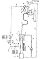
- the figure shows the basic structure of an arrangement which works according to the method according to the invention.
- an application device 3 for example a spray gun
- the robot guides the application device 3 at a certain speed along a path close to the surface of a workpiece 2, on which an adhesive seam is to be applied.
- the application device 3 is connected via a flexible hose 4 to a cylinder 7, in which there is hot or cold adhesive, which is filled in at the beginning of a working cycle via a line 15 and a valve 13 by means of a pump 14.
- a piston 9 is arranged, the drive 10 is designed so that it moves the piston against the adhesive with an adjustable constant pressure.
- the path traversed by the robot is divided into individual path sections, which path sections can be straight or curved sections.
- the time to pass through a section of a path is called a cycle.
- Running through the entire path represents a work cycle.
- a change of direction often takes place at the ends of the path sections.
- the robot usually travels the path at its maximum possible speed. This is usually smaller for curved path sections than for straight ones.
- the application device has a nozzle opening, the average cross section of which can be changed by means of an adjusting device (not shown).
- This adjustment option serves as an actuator for regulating the flow of liquid.
- the adjustment takes place, for example, by rotating or translationally displacing a piston rod, and by measuring the position of this piston rod, a value is obtained for the size of the nozzle opening, which is used as the actual value fi for the flow. In the figure, this measuring element is only symbolically indicated at point 31 tet.
- a comparator 32 the actual flow value f i is compared with a desired flow value f s and the control deviation ⁇ f acts on a controller 33, which controls an adjusting element present in the application device, which is symbolically indicated by 34.
- the setpoint f for the flow is composed of an s basic setpoint f sg and a correction setpoint K, which is added algebraically to the basic setpoint in the summation element 18.
- the basic setpoint is based on a specific viscosity of the liquid and a specific relationship between the nozzle opening and the actuator 34 for the nozzle opening of the application device.
- the correction setpoint K detects and compensates for changes in viscosity and changes in the nozzle opening due to wear, given the position of the actuator.
- the partial paths x i which the piston 9 travels in the cylinder 5 during the passage of the individual cycles of a working cycle of the robot, are measured by means of a symbolically represented path meter 16.
- These values x i are subtracted in a summing element 19 from corresponding target values for the amount of viscous liquid to be applied per cycle.
- These setpoints come from a setpoint generator 20, which is symbolically indicated in the figure for a work cycle consisting of n cycles.
- the difference values x s - x i for the individual cycles form the correction values for the setpoint. They are stored in a memory 21 during the work cycle currently being carried out.
- the correction setpoints obtained in the previous work cycle are added algebraically to the basic setpoint f sg .
- This basic setpoint can also have different values for the individual cycles of the work cycle, which is the case, for example, if the web speed changes during the transition from one cycle to the next cycle, but the seam thickness to be applied is to remain constant.
- the pressure exerted on the piston 9 by the drive arrangement 10 can be increased.
- the signal ⁇ f is expediently brought into effect via the signal line 36 on the drive 10 of the piston via a threshold value element (not shown).
- an adjustment of the nozzle opening is also necessary, for example, if the thickness of the seam is to be changed during the transition from one web section (cycle) to the next web section.
- the time available for this adjustment is extremely short since the robot's dwell status during this transition is very short. For example, it is about 20 ms.
- the adjustment of the nozzle opening can be carried out by means of an electric drive which is operated with clocked direct current, with an overvoltage being used for a short time.
- the method according to the invention is also useful if the liquid flow is not regulated, but only controlled, that is, the actual value f i is not recorded.
Abstract
Verfahren zur Regelung oder Steuerung des Flusses einer zähen Flüssigkeit, beispielsweise eines Klebers oder einer Kunststoffmasse, die von einer von einem Roboter geführten Auftragevorrichtung (3) als Naht (1) auf einen Körper (2) aufgetragen wird, wobei die zähe Flüssigkeit der Auftragevorrichtung aus einem Zylinder (7) fortlaufend zugeführt wird, in welchem ein von einer Antriebsvorrichtung (10) verschiebbarer Kolben (9) einen konstanten Druck auf die Flüssigkeit ausübt. Gemäß der Erfindung wird der Weg (xi) gemessen, den der Kolben (9) in der Zeit zurücklegt, in der der Roboter eine bestimmte Bahnstrecke (n) durchläuft. Der Meßwert (xi) für den Kolbenweg wird mit einem Sollwert (xs) für den Kolbenweg verglichen, und der Differenzwert (xs - xi) wird und beim erneuten Durchlaufen derselben Bahnstrecke während des nächsten Arbeitszyklus als Korrektursollwert (K) algebraisch zu einem Grundsollwert (fsg) für eine Regelung oder eine Steuerung der Düsenöffnung der Auftragevorrichtung (3) addiert. Auf diese Weise wird der Einfluß von Viskositätsänderungen und Abnutzungen der Düsenöffnung auf die Dicke der aufgetragenen Naht ausgeschaltet.Method for regulating or controlling the flow of a viscous liquid, for example an adhesive or a plastic mass, which is applied as a seam (1) to a body (2) by an application device (3) guided by a robot, the viscous liquid from the application device a cylinder (7) is continuously fed, in which a piston (9) displaceable by a drive device (10) exerts a constant pressure on the liquid. According to the invention, the path (xi) is measured, which the piston (9) travels in the time in which the robot travels a certain path (s). The measured value (xi) for the piston travel is compared with a setpoint (xs) for the piston travel, and the difference value (xs - xi) is algebraically compared to a basic setpoint (fsg ) for a regulation or a control of the nozzle opening of the application device (3) added. In this way, the influence of changes in viscosity and wear of the nozzle opening on the thickness of the applied seam is eliminated.
Description
Verfahren zur Regelung oder Steuerung des Flusses einer zähen Flüssigkeit, die von einer Maschine selbstätig als Naht aufgetragen wird.Process for regulating or controlling the flow of a viscous liquid that is automatically applied as a seam by a machine.
Die vorliegende Erfindung betrifft ein Verfahren zur Regelung oder Steuerung des Flusses einer zähen Flüssigkeit gemäß dem Oberbegriff des Anspruches 1.The present invention relates to a method for regulating or controlling the flow of a viscous liquid according to the preamble of claim 1.
In der Industrie werden Automaten, insbesondere Roboter unter anderem dafür eingesetzt, auf vorgegebenen Bahnen selbstätig eine Naht aus einer zähen Flüssigkeit aufzutragen. Bei der zähen Flüssigkeit kann es sich beispielsweise um einen Kleber, eine Dichtungsmasse oder eine Kunststoffmasse handeln. Ein konkretes Beispiel stellt das von einem gesteuerten Roboter ausgeführte Auftragen eines Klebers längs einer bestimmten Bahn auf einem Werkstück dar. Dieser Vorgang kommt beispielsweise in der Autoindustrie vor beim Auftragen eines Klebers oder einer Dichtungsmasse auf der Innenseite des Außenbleches von Autotüren, auf die anschließend das Innenblech der Tür aufgeklebt wird.In industry, automatic machines, in particular robots, are used, among other things, to automatically apply a seam made of a viscous liquid on predetermined paths. The viscous liquid can be, for example, an adhesive, a sealing compound or a plastic compound. A concrete example is the application of an adhesive carried out by a controlled robot along a specific path on a workpiece. This process occurs, for example, in the automotive industry when an adhesive or a sealant is applied to the inside of the outer panel of car doors, to which the inner panel is then applied the door is stuck on.
Ein Problem bei dieser Technik besteht darin, sicherzustellen, daß die aufgetragene Naht tatsächlich die gewünschte Dicke hat, d.h. pro Längeneinheit der Bahn eine gewünschte Menge der zähen Flüssigkeit aufgetragen wird. Die pro Zeiteinheit ausgespritzte oder aufgetragene Menge wird Fluß genannt. Der aus der Auftragevorrichtung austretende Fluß muß also in einem bestimmten Verhältnis zu der sich innerhalb eines Arbeitszyklus häufig ändernden Bahngeschwindigkeit des Roboters stehen.A problem with this technique is to ensure that the applied seam is actually the desired thickness, that is, a desired amount of the viscous liquid is applied per unit length of the web. The amount sprayed or applied per unit of time is called flow. The flow emerging from the applicator must therefore be in a certain ratio to the inner the robot's path speed, which changes frequently within one working cycle.
Zur Durchführung des vorgenannten Verfahrens ist es bekannt, die vom Roboterarm geführte Auftragevorrichtung über einen flexiblen Schlauch mit der zähen Flüssigkeit zu versorgen, wobei der Schlauch an einen mit der zähen Flüssigkeit gefüllten Zylinder angeschlossen ist, dessen Kolben mit konstanter Kraft die Flüssigkeit aus dem Zylinder herausdrückt. Durch Einstellung dieser Kraft kann der Flüssigkeitsfluß verändert werden. Bei diesem bekannten Verfahren kann der Flüssigkeitsfluß jedoch infolge unterschiedlicher Viskosität, die sich mit der Temperatur ändert, sowie durch Verschleiß an der Düsenöffnung der Auftragevorrichtung von dem gewünschten Wert abweichen.To carry out the aforementioned method, it is known to supply the application device guided by the robot arm with the viscous liquid via a flexible hose, the hose being connected to a cylinder filled with the viscous liquid, the piston of which presses the liquid out of the cylinder with constant force . By adjusting this force, the fluid flow can be changed. In this known method, however, the liquid flow can deviate from the desired value due to different viscosity, which changes with the temperature, as well as due to wear at the nozzle opening of the application device.
Ferner ist es bereits bekannt, zur Einstellung der Dicke der Flüssigkeitsnaht den Antrieb des Kolbens in dem vorgenannten Zylinder so auszubilden, daß der Kolben unabhängig vom zu überwindenden Widerstand mit einer einstellbaren konstanten Geschwindigkeit arbeitet. Die Auftragevorrichtung arbeitet bei diesem Verfahren mit konstanter Düsenöffnung. Eine Kontrolle, ob die aufgetragene Menge pro Zeiteinheit dem gewünschten Wert entspricht, findet nicht statt. Eine Verstellung ist nur durch Veränderung der Geschwindigkeit des Kolbens möglich, und diese Verstellung ist mit einer großen Zeitkonstanten behaftet. Beim Übergang von einem Takt zum nächtsten innerhalb eines Arbeitszyklus wird häufig die Geschwindigkeit und/oder die pro Längeneinheit aufzutragende Menge der zähen Flüssigkeit geändert, so daß in diesen Zeitpunkten der Flüssigkeitsfluß geändert werden muß. Hierbei erweist sich die hohe Viskosität und damit die Trägheit des Klebers als nachteilig. Für den Übergang von einem zum näch- sten Bahnabschnitt steht nur eine sehr kurze/zur Verfugung, und innerhalb dieser Zeit muß die erforderliche Flußänderung durchgeführt werden. Außerdem machen sich bei diesem Verfahren die Druckänderungen in der zähen Flüssigkeit störend be merkbar, und zwar einerseits deshalb, weil die zähe Flüssigkeit eine spürbare Kompressibilität aufweist, und andererseits deshalb, weil die Zuführungsschläuche bei den hohen Betriebsdrücken von 100 bis 200 bar expandieren und bei Druckentlastung sich zusammenziehen. Dadurch entstehen in Form transienter Vorgänge Schwankungen in der pro Längeneinheit aufgetragenen zähen Flüssigkeit. Der letztgenannte Effekt könnte zwar durch Anbringung der Kolben-Zylinderanordnung auf der Roboterhand weitgehend vermindert werden, jedoch würde dann das Gewicht des für schnelle Bewegungen bestimmten Roboterarms erheblich vergrößert werden, was wiederum die Auftragegeschwindigkeit nachteilig beeinflussen würde.Furthermore, it is already known to set the drive of the piston in the aforementioned cylinder so that the piston works at an adjustable constant speed regardless of the resistance to be overcome to adjust the thickness of the liquid seam. In this process, the application device works with a constant nozzle opening. A check is not carried out to determine whether the quantity applied per unit of time corresponds to the desired value. An adjustment is only possible by changing the speed of the piston, and this adjustment is associated with a large time constant. During the transition from one cycle to the next within a work cycle, the speed and / or the amount of viscous liquid to be applied per unit length is often changed, so that the liquid flow must be changed at these times. The high viscosity and thus the inertia of the adhesive prove to be disadvantageous. Only a very short / is available for the transition from one to the next rail section, and the required flow change must be carried out within this time. In addition, in this procedure Ren the pressure changes in the viscous liquid are noticeably noticeable, on the one hand because the viscous liquid has a noticeable compressibility, and on the other hand because the supply hoses expand at the high operating pressures of 100 to 200 bar and contract when the pressure is released. This creates fluctuations in the form of transient processes in the viscous liquid applied per unit length. Although the latter effect could be largely reduced by attaching the piston-cylinder arrangement to the robot hand, the weight of the robot arm intended for fast movements would then be considerably increased, which in turn would adversely affect the application speed.
Der Erfindung liegt die Aufgabe zugrunde, ein Verfahren der eingangs genannten Art zu entwickeln, bei welchem der aus der Auftragevorrichtung austretende Flüssigkeitsfluß unabhängig von der Viskosität der Flüssigkeit und vom Abnutzungszustand der Düse der Auftragevorrichtung ist und bei welchem bei einer Änderung der Bahngeschwindigkeit oder der pro Längeneinheit der Bahn aufzutragenden Flüssigkeitsmenge die Auftragevorrichtung sehr schnell anspricht.The invention has for its object to develop a method of the type mentioned, in which the liquid flow emerging from the application device is independent of the viscosity of the liquid and the state of wear of the nozzle of the application device and in which with a change in the web speed or per unit length the amount of liquid to be applied to the web responds very quickly to the application device.
Zur Lösung dieser Aufgabe wird ein Verfahren gemäß dem Oberbegriff des Anspruches 1 vorgeschlagen, welches erfindungsgemäß die im kennzeichnenden Teil des Anspruches 1 genannten Merkmale hat.To achieve this object, a method is proposed according to the preamble of claim 1, which according to the invention has the features mentioned in the characterizing part of claim 1.
Vorteilhafte Ausgestaltungen der Erfindung sind in den weiteren Ansprüchen genannt.Advantageous embodiments of the invention are mentioned in the further claims.
Anhand des in der Figur gezeigten Ausführungsbeispiels soll die Erfindung näher erläutert werden. Die Figur zeigt den prinzipiellen Aufbau einer Anordnung, die nach dem Verfahren gemäß der Erfindung arbeitet.On the basis of the embodiment shown in the figure, the invention will be explained in more detail. The figure shows the basic structure of an arrangement which works according to the method according to the invention.
Mit 6 ist der Arm eines im übrigen nicht dargestellten Roboters bezeichnet, an dessen freies Ende mittels eines Greifwerkzeuges eine Auftragevorrichtung 3, zum Beispiel eine Spritzpistole, eingespannt ist. Der Roboter führt die Auftragevorrichtung 3 mit einer bestimmten Geschwindigkeit längs einer Bahn nahe an der Oberfläche eines Werkstückes 2, auf welcher eine Klebernaht aufgetragen werden soll. Die Auftragevorrichtung 3 ist über einen flexiblen Schlauch 4 an einen Zylinder 7 angeschlossen, in welchem sich heißer oder kalter Kleber befindet, der zu Beginn eines Arbeitszyklus über eine Leitung 15 und ein Ventil 13 mittels einer Pumpe 14, eingefüllt wird. Im Zylinder 7 ist ein Kolben 9 angeordnet, dessen Antrieb 10 so ausgelegt ist, daß er den Kolben mit einem einstellbaren konstanten Druck gegen den Kleber verschiebt.6 with the arm of a robot, not otherwise shown, is designated, on the free end of which an application device 3, for example a spray gun, is clamped by means of a gripping tool. The robot guides the application device 3 at a certain speed along a path close to the surface of a workpiece 2, on which an adhesive seam is to be applied. The application device 3 is connected via a flexible hose 4 to a
Die vom Roboter durchlaufene Bahn ist in einzelne Bahnabschnitte unterteilt, wobei diese Bahnabschnitte gerade oder gekrümmte Abschnitte sein können. Die Zeit zum Durchlaufen eines Bahnabschnittes wird Takt genannt. Das Durchlaufen der gesamten Bahn stellt einen Arbeitszyklus dar. An den Enden der Bahnabschnitte findet häufig eine Richtungsänderung statt. Der Roboter durchfährt die Bahn in der Regel mit seiner maximal möglichen Geschwindigkeit. Diese ist für gekrümmte Bahnabschnitte in der Regel kleiner als für gerade.The path traversed by the robot is divided into individual path sections, which path sections can be straight or curved sections. The time to pass through a section of a path is called a cycle. Running through the entire path represents a work cycle. A change of direction often takes place at the ends of the path sections. The robot usually travels the path at its maximum possible speed. This is usually smaller for curved path sections than for straight ones.
Die Auftragevorrichtung hat eine Düsenöffnung, deren Durchschnittsquerschnitt mittels einer nicht dargestellten Verstellvorrichtung verändert werden kann. Diese Verstellmöglichkeit dient als Stellglied für die Regelung des Flüssigkeitsflusses. Die Verstellung erfolgt beispielsweise durch Drehung oder translatorische Verschiebung einer Kolbenstange, und durch Messung der Stellung dieser Kolbenstange erhält man einen Wert für die Größe der Düsenöffnung, der als Istwert f i für den Fluß verwendet wird. In der Figur ist dieses Meßglied nur symbolisch an der Stelle 31 angedeutet. In einem Vergleichglied 32 wird der Flußistwert fi mit einem Flußsollwert fs verglichen und die Regelabweichung Δf beaufschlagt einen Regler 33, der ein in der Auftragevorrichtung vorhandenes Verstellglied, das symbolisch mit 34 angedeutet ist, steuert.The application device has a nozzle opening, the average cross section of which can be changed by means of an adjusting device (not shown). This adjustment option serves as an actuator for regulating the flow of liquid. The adjustment takes place, for example, by rotating or translationally displacing a piston rod, and by measuring the position of this piston rod, a value is obtained for the size of the nozzle opening, which is used as the actual value fi for the flow. In the figure, this measuring element is only symbolically indicated at point 31 tet. In a
Der Sollwert f für den Fluß setzt sich zusammen aus einem s Grundsollwert f sg und einem Korrektursollwert K, der im Summierungsglied 18 algebraisch zu dem Grundsollwert addiert wird. Der Grundsollwert geht von einer bestimmten Viskosität der Flüssigkeit und einem bestimmten Zusammenhang zwischen der Düsenöffnung und dem Stellglied 34 für die Düsenöffnung der Auftragevorrichtung aus. Durch den Korrektursollwert K werden Viskositätsänderungen sowie durch Abnutzung bedingte Veränderungen der Düsenöffnung bei gegebener Stellung des Stellgliedes erfaßt und kompensiert. Zu diesem Zweck werden mittels eines symbolisch dargestellten Wegmessers 16 die Teilwege xi gemessen, die der Kolben 9 im Zylinder 5 während des Durchlaufens der einzelnen Takte eines Arbeitszyklus des Roboters zurücklegt. Diese Werte xi werden in einem Summierungsglied 19 von entsprechenden Sollwerten für die pro Takt aufzutragende Menge der zähen Flüssigkeit subtrahiert. Diese Sollwerte kommen von einem Sollwertgeber 20, der in der Figur für einen Arbeitszyklus aus n Takten symbolisch angedeutet ist. Die Differenzwerte xs - xi für die einzelnen Takte bilden die Korrekturwerte für den Sollwert. Sie werden während des gerade in Ausführung begriffenen Arbeitszyklus in einem Speicher 21 gespeichert. Im darauffolgenden Arbeitszyklus werden die im vorangegangenen Arbeitszyklus gewonnenen Korrektursollwerte zu dem Grundsollwert fsg algebraisch addiert. Auch dieser Grundsollwert kann grundsätzlich für die einzelnen Takte des Arbeitszyklus unterschiedliche Werte haben, was beispielsweise dann der Fall ist, wenn beim Übergang von einem Takt zum nächsten Takt sich die Bahngeschwindigkeit ändert, die aufzutragende Nahtdicke aber konstant bleiben soll.The setpoint f for the flow is composed of an s basic setpoint f sg and a correction setpoint K, which is added algebraically to the basic setpoint in the
Für den Fall, daß das Stellglied 34 an die obere Grenze seines Verstellbereiches stößt (maximale Öffnung der Düse), ohne daß der Flußistwert den Flußsollwert erreicht, kann der von der Antriebsanordnung 10 auf den Kolben 9 ausgeübte Druck erhöht werden. Zu diesem Zweck wird das Signal Δ f, zweckmäßigerweise über ein nicht dargestelltes Schwellwertglied, über die Signalleitung 36 auf den Antrieb 10 des Kolbens zur Einwirkung gebracht.In the event that the actuator 34 hits the upper limit of its adjustment range (maximum opening of the nozzle) without the actual flow value reaching the desired flow value, the pressure exerted on the piston 9 by the
Wie bereits festgestellt wurde, ist eine Verstellung der Düsenöffnung beispielsweise auch dann erforderlich, wenn die Dicke der Naht beim Übergang von einem Bahnabschnitt (Takt) zum nächsten Bahnabschnitt verändert werden soll. Die für diese Verstellung verfügbare Zeit ist außerordentlich gering, da der Verweilzustand des Roboters bei diesem Übergang sehr kurz ist. Sie liegt beispielsweise bei etwa 20 ms. Um die hierfür erforderliche sehr schnelle Verstellung der Düsenöffnung sicher zu stellen, kann die Verstellung der Düsenöffnung mittels eines elektrischen Antriebs erfolgen, der mit getaktetem Gleichstrom betrieben wird, wobei kurzfristig mit einer Überspannung gearbeitet wird.As already stated, an adjustment of the nozzle opening is also necessary, for example, if the thickness of the seam is to be changed during the transition from one web section (cycle) to the next web section. The time available for this adjustment is extremely short since the robot's dwell status during this transition is very short. For example, it is about 20 ms. In order to ensure the very rapid adjustment of the nozzle opening required for this purpose, the adjustment of the nozzle opening can be carried out by means of an electric drive which is operated with clocked direct current, with an overvoltage being used for a short time.
Das Verfahren nach der Erfindung ist auch sinnvoll, wenn der Flüssigkeitsfluß nicht geregelt, sondern nur gesteuert wird, also eine Erfassung des Istwertes fi nicht stattfindet.The method according to the invention is also useful if the liquid flow is not regulated, but only controlled, that is, the actual value f i is not recorded.
Claims (3)
Applications Claiming Priority (2)
| Application Number | Priority Date | Filing Date | Title |
|---|---|---|---|
| DE19853506110 DE3506110A1 (en) | 1985-02-22 | 1985-02-22 | METHOD FOR REGULATING OR CONTROLLING THE FLOW OF A TOE LIQUID APPLIED AS A SEAM BY A MACHINE |
| DE3506110 | 1985-02-22 |
Publications (3)
| Publication Number | Publication Date |
|---|---|
| EP0192166A2 true EP0192166A2 (en) | 1986-08-27 |
| EP0192166A3 EP0192166A3 (en) | 1988-04-13 |
| EP0192166B1 EP0192166B1 (en) | 1991-05-08 |
Family
ID=6263204
Family Applications (1)
| Application Number | Title | Priority Date | Filing Date |
|---|---|---|---|
| EP86101719A Expired - Lifetime EP0192166B1 (en) | 1985-02-22 | 1986-02-11 | Flow regulation or control method for a viscous fluid dispensed as a seam |
Country Status (4)
| Country | Link |
|---|---|
| US (1) | US4666732A (en) |
| EP (1) | EP0192166B1 (en) |
| JP (1) | JPS61228511A (en) |
| DE (2) | DE3506110A1 (en) |
Cited By (2)
| Publication number | Priority date | Publication date | Assignee | Title |
|---|---|---|---|---|
| EP0529686A2 (en) * | 1986-10-30 | 1993-03-03 | Nordson Corporation | Method of compensating for changes in the flow characteristic of a fluid being dispensed from a nozzle |
| EP3486184A1 (en) * | 2017-11-02 | 2019-05-22 | Krones AG | Flow measurement for glue supply |
Families Citing this family (24)
| Publication number | Priority date | Publication date | Assignee | Title |
|---|---|---|---|---|
| US4922852A (en) * | 1986-10-30 | 1990-05-08 | Nordson Corporation | Apparatus for dispensing fluid materials |
| DE3700212A1 (en) * | 1987-01-07 | 1988-07-21 | Hans Liman | Process and device for the metered dispensing of a viscous medium, in particular an adhesive |
| DE3728054A1 (en) * | 1987-08-20 | 1989-03-02 | Klatt Helmuth | METHOD AND DEVICE FOR DOSING AND APPLYING LIQUID OR PASTOUS MEDIA TO AN OBJECT |
| DE3822835A1 (en) * | 1988-07-06 | 1990-03-08 | Josef Schucker | Process and arrangement for coating workpiece surfaces |
| US5232736A (en) * | 1989-07-24 | 1993-08-03 | Motorola, Inc. | Method for controlling solder printer |
| JP2810456B2 (en) * | 1989-11-30 | 1998-10-15 | サンスター技研株式会社 | Detection method of bead breakage of coating material |
| DE4004198A1 (en) * | 1990-02-12 | 1991-08-14 | Max Planck Gesellschaft | Controlling biochemical liq. injection into multiple oocytes - by automatic delivery from valve-controlled cannula |
| US5143744A (en) * | 1991-06-19 | 1992-09-01 | Minnesota Mining And Manufacturing Company | Dynamic contact angle measurement system |
| ES2117085T3 (en) * | 1992-11-20 | 1998-08-01 | Nordson Corp | A PROCEDURE FOR MONITORING AND / OR DISPENSING MATERIALS ON A SUBSTRATE. |
| US5489337A (en) * | 1993-01-28 | 1996-02-06 | Kabushiki Kaisha Toshiba | Apparatus for applying organic material to semiconductor wafer in which the nozzle opening adjusts in response to data |
| US5499745A (en) * | 1994-02-18 | 1996-03-19 | Nordson Corporation | Apparatus for mixing and dispensing two chemically reactive materials |
| US5687092A (en) * | 1995-05-05 | 1997-11-11 | Nordson Corporation | Method of compensating for changes in flow characteristics of a dispensed fluid |
| EP0854759B1 (en) | 1995-10-13 | 2004-01-28 | Nordson Corporation | Flip chip underfill system and method |
| SE508434C2 (en) * | 1996-02-23 | 1998-10-05 | Scanrex Automation Ab | Method and system of dosing |
| US6173864B1 (en) | 1999-04-23 | 2001-01-16 | Nordson Corporation | Viscous material dispensing system and method with feedback control |
| US6541063B1 (en) | 1999-11-04 | 2003-04-01 | Speedline Technologies, Inc. | Calibration of a dispensing system |
| DE10048749A1 (en) * | 2000-09-29 | 2002-04-11 | Josef Schucker | Arrangement for applying adhesive to a workpiece |
| DE10239351B4 (en) * | 2002-08-28 | 2006-07-27 | Amtec Kistler Gmbh | Device for applying a coating agent |
| US20040148763A1 (en) * | 2002-12-11 | 2004-08-05 | Peacock David S. | Dispensing system and method |
| DE10361018C9 (en) | 2003-12-23 | 2021-03-04 | QUISS Qualitäts-Inspektionssysteme und Service GmbH | Method for recognizing a structure to be applied to a substrate with a plurality of cameras and a device therefor |
| CN102830645B (en) * | 2012-09-26 | 2014-11-12 | 苏州工业园区职业技术学院 | Uniaxial full-automatic high-speed dispensing robot servo control system |
| DE102015001211A1 (en) | 2015-01-30 | 2015-07-02 | Daimler Ag | Arrangement with a robot, a glue tool and a holding station |
| CN105005325B (en) * | 2015-06-16 | 2018-02-23 | 王晓冉 | The method of automatic resistance trimming and automatic resistance trimming equipment are carried out to foil resistance strain gauge |
| DE102015121449A1 (en) * | 2015-12-09 | 2017-06-14 | Ba Assembly & Turnkey Systems Gmbh | Verstreicheinheit |
Citations (4)
| Publication number | Priority date | Publication date | Assignee | Title |
|---|---|---|---|---|
| US3890922A (en) * | 1974-03-22 | 1975-06-24 | George F Nordenholt | Sealant applying apparatus |
| US4026439A (en) * | 1975-06-18 | 1977-05-31 | Cocks Eric H | Precision fluid dispensing and mixing system |
| JPS59100069A (en) * | 1982-11-30 | 1984-06-09 | Sunstar Giken Kk | Sealing method of car body |
| EP0125771A2 (en) * | 1983-05-11 | 1984-11-21 | Nordson Corporation | Method and apparatus for sealing welded seams of automobiles |
Family Cites Families (4)
| Publication number | Priority date | Publication date | Assignee | Title |
|---|---|---|---|---|
| US1987197A (en) * | 1925-06-30 | 1935-01-08 | Better Packages Inc | Strip serving device |
| US4251566A (en) * | 1978-10-12 | 1981-02-17 | Champion International Corporation | Gum thickness regulator |
| US4367244A (en) * | 1980-10-27 | 1983-01-04 | Oregon Graduate Center For Study And Research | Method for monitoring and controlling the distribution of droplets on a surface |
| US4417934A (en) * | 1980-11-05 | 1983-11-29 | Imperial Group Plc | Monitoring a deposit on a travelling web |
-
1985
- 1985-02-22 DE DE19853506110 patent/DE3506110A1/en active Granted
-
1986
- 1986-02-11 EP EP86101719A patent/EP0192166B1/en not_active Expired - Lifetime
- 1986-02-11 DE DE8686101719T patent/DE3679081D1/en not_active Expired - Lifetime
- 1986-02-21 JP JP61037161A patent/JPS61228511A/en active Pending
- 1986-02-24 US US06/832,434 patent/US4666732A/en not_active Expired - Lifetime
Patent Citations (4)
| Publication number | Priority date | Publication date | Assignee | Title |
|---|---|---|---|---|
| US3890922A (en) * | 1974-03-22 | 1975-06-24 | George F Nordenholt | Sealant applying apparatus |
| US4026439A (en) * | 1975-06-18 | 1977-05-31 | Cocks Eric H | Precision fluid dispensing and mixing system |
| JPS59100069A (en) * | 1982-11-30 | 1984-06-09 | Sunstar Giken Kk | Sealing method of car body |
| EP0125771A2 (en) * | 1983-05-11 | 1984-11-21 | Nordson Corporation | Method and apparatus for sealing welded seams of automobiles |
Non-Patent Citations (1)
| Title |
|---|
| PATENT ABSTRACTS OF JAPAN, Band 8, Nr. 216 (M-329)[1653], 3. Oktober 1984; & JP-A-59 100 069 (SANSUTAA GIKEN K.K.) 09-06-1984 * |
Cited By (3)
| Publication number | Priority date | Publication date | Assignee | Title |
|---|---|---|---|---|
| EP0529686A2 (en) * | 1986-10-30 | 1993-03-03 | Nordson Corporation | Method of compensating for changes in the flow characteristic of a fluid being dispensed from a nozzle |
| EP0529686A3 (en) * | 1986-10-30 | 1993-05-05 | Nordson Corporation | Method of compensating for changes in the flow characteristic of a fluid being dispensed from a nozzle |
| EP3486184A1 (en) * | 2017-11-02 | 2019-05-22 | Krones AG | Flow measurement for glue supply |
Also Published As
| Publication number | Publication date |
|---|---|
| US4666732A (en) | 1987-05-19 |
| DE3506110A1 (en) | 1986-09-04 |
| DE3679081D1 (en) | 1991-06-13 |
| DE3506110C2 (en) | 1987-07-09 |
| EP0192166B1 (en) | 1991-05-08 |
| JPS61228511A (en) | 1986-10-11 |
| EP0192166A3 (en) | 1988-04-13 |
Similar Documents
| Publication | Publication Date | Title |
|---|---|---|
| EP0192166B1 (en) | Flow regulation or control method for a viscous fluid dispensed as a seam | |
| EP2036618B1 (en) | Metering system for a coating assembly | |
| EP0021182B1 (en) | Method and apparatus for supplying paint to painting installations | |
| DE102005014416B4 (en) | An air-cylinder device and control method therefor | |
| EP0288878B1 (en) | Method for automatically coating work pieces in series | |
| DE69723817T2 (en) | METHOD AND SYSTEM FOR DELIVERING A VISCOSE SOLUTION | |
| DE3822835A1 (en) | Process and arrangement for coating workpiece surfaces | |
| EP1152155B1 (en) | Device for setting the differential pressure in a fluid cylinder | |
| DE19625880C2 (en) | Automatic machine setting procedure for controlling injection molding speed | |
| EP0761334A1 (en) | Tube bending machine | |
| DE1267066B (en) | Device for height or side adjustment of a welding or cutting torch | |
| EP0632202B1 (en) | Process for the operation of a pressure medium actuated positioner or gripping clamping device | |
| CH668566A5 (en) | ARRANGEMENT ON ROAD MARKING MACHINES FOR THE AUTOMATIC CONTINUOUS MAINTENANCE OF THE LAYER THICKNESS OF MARKING LINES. | |
| DE2544794A1 (en) | Hydraulic press with accumulator - has stroke of moving press accurately adjusted using feedback circuit from sensor amplifier | |
| EP1270086B1 (en) | Coating apparatus and process for controlling a coating device with different nozzles | |
| EP0806256B1 (en) | Method for controlling the material flow during the drawing of sheet metal parts and device for carrying out the method | |
| DE3700212C2 (en) | ||
| DE2056071A1 (en) | Hydraulic adjustment device for tools | |
| DE102004031031A1 (en) | Device for applying high-viscosity masses to a workpiece surface | |
| DE19649461C2 (en) | Method and device for applying a viscous material | |
| DE3543655C2 (en) | ||
| DE3019998A1 (en) | DEVICE FOR CONTROLLING THE EXPANSION OF THE LAEPPING TOOL OF A LAEPPING MACHINE | |
| DE102005033292A1 (en) | Adhesive/sealing material applying device for use at motor vehicle door, has control valve, having body actuated by servo converter, controlled by signals to adjust its discharge pressure to preset value, independent of input pressure | |
| DE2101907C3 (en) | Method and device for coating the inner walls of pipes | |
| DE3123257A1 (en) | Hydraulic control device |
Legal Events
| Date | Code | Title | Description |
|---|---|---|---|
| PUAI | Public reference made under article 153(3) epc to a published international application that has entered the european phase |
Free format text: ORIGINAL CODE: 0009012 |
|
| AK | Designated contracting states |
Kind code of ref document: A2 Designated state(s): DE FR GB SE |
|
| PUAL | Search report despatched |
Free format text: ORIGINAL CODE: 0009013 |
|
| AK | Designated contracting states |
Kind code of ref document: A3 Designated state(s): DE FR GB SE |
|
| RAP1 | Party data changed (applicant data changed or rights of an application transferred) |
Owner name: SCHUCKER, JOSEF |
|
| RIN1 | Information on inventor provided before grant (corrected) |
Inventor name: SCHUCKER, JOSEF |
|
| 17P | Request for examination filed |
Effective date: 19880625 |
|
| 17Q | First examination report despatched |
Effective date: 19900730 |
|
| GRAA | (expected) grant |
Free format text: ORIGINAL CODE: 0009210 |
|
| AK | Designated contracting states |
Kind code of ref document: B1 Designated state(s): DE FR GB SE |
|
| REF | Corresponds to: |
Ref document number: 3679081 Country of ref document: DE Date of ref document: 19910613 |
|
| ET | Fr: translation filed | ||
| GBT | Gb: translation of ep patent filed (gb section 77(6)(a)/1977) | ||
| PLBE | No opposition filed within time limit |
Free format text: ORIGINAL CODE: 0009261 |
|
| STAA | Information on the status of an ep patent application or granted ep patent |
Free format text: STATUS: NO OPPOSITION FILED WITHIN TIME LIMIT |
|
| 26N | No opposition filed | ||
| EAL | Se: european patent in force in sweden |
Ref document number: 86101719.2 |
|
| REG | Reference to a national code |
Ref country code: GB Ref legal event code: IF02 |
|
| PGFP | Annual fee paid to national office [announced via postgrant information from national office to epo] |
Ref country code: FR Payment date: 20050113 Year of fee payment: 20 |
|
| PGFP | Annual fee paid to national office [announced via postgrant information from national office to epo] |
Ref country code: GB Payment date: 20050118 Year of fee payment: 20 |
|
| PGFP | Annual fee paid to national office [announced via postgrant information from national office to epo] |
Ref country code: SE Payment date: 20050124 Year of fee payment: 20 |
|
| PGFP | Annual fee paid to national office [announced via postgrant information from national office to epo] |
Ref country code: DE Payment date: 20050215 Year of fee payment: 20 |
|
| PG25 | Lapsed in a contracting state [announced via postgrant information from national office to epo] |
Ref country code: GB Free format text: LAPSE BECAUSE OF EXPIRATION OF PROTECTION Effective date: 20060210 |
|
| REG | Reference to a national code |
Ref country code: GB Ref legal event code: PE20 |
|
| EUG | Se: european patent has lapsed |