EP0529541B1 - Double beam detector system for liquid chromatography - Google Patents
Double beam detector system for liquid chromatography Download PDFInfo
- Publication number
- EP0529541B1 EP0529541B1 EP92114331A EP92114331A EP0529541B1 EP 0529541 B1 EP0529541 B1 EP 0529541B1 EP 92114331 A EP92114331 A EP 92114331A EP 92114331 A EP92114331 A EP 92114331A EP 0529541 B1 EP0529541 B1 EP 0529541B1
- Authority
- EP
- European Patent Office
- Prior art keywords
- entrance
- cell
- bore
- lens
- beams
- Prior art date
- Legal status (The legal status is an assumption and is not a legal conclusion. Google has not performed a legal analysis and makes no representation as to the accuracy of the status listed.)
- Expired - Lifetime
Links
Images
Classifications
-
- G—PHYSICS
- G01—MEASURING; TESTING
- G01N—INVESTIGATING OR ANALYSING MATERIALS BY DETERMINING THEIR CHEMICAL OR PHYSICAL PROPERTIES
- G01N30/00—Investigating or analysing materials by separation into components using adsorption, absorption or similar phenomena or using ion-exchange, e.g. chromatography or field flow fractionation
- G01N30/02—Column chromatography
- G01N30/62—Detectors specially adapted therefor
- G01N30/74—Optical detectors
- G01N2030/746—Optical detectors detecting along the line of flow, e.g. axial
Definitions
- the present invention relates to a double beam detector system for liquid chromatography, comprising
- LC liquid chromatography
- a substance whose quantitative presence in a sample is to be determined is injected and dissolved into a suitable liquid carrier solvent, separated in an LC column and flowed through a detector cell which has end windows through which a selected wavelength of ultraviolet or visible light radiation is directed.
- Radiation exiting from the cell falls on a photodetector having an output recorded by suitable instrumentation which is calibrated to indicate the amount of radiation absorbed by the fluid flowing through the cell.
- Absorbance is customarily indicated by a graph continuously recorded on a strip chart by a pen recorder.
- the quantitative presence of a sample substance of interest is determined by measuring the area under the graph peaks which represent the amount of radiation of a particular wavelength that is absorbed, particular materials being identified by particular wavelengths characteristically absorbed by them.
- the sensitivity of a spectrophotometer detector cell is a function particularly of the stability of the base line of the graph.
- the graph base line is established by the absorbance of the solvent used, and will change in relation to any change in the refractive index of the solvent.
- the refractive index in turn will be changed by a change in the temperature of the solvent in the cell, or by a transient as a test sample reaches the cell.
- Transients are particularly associated with temporary changes in refractive index on the fluid near the wall of the cell.
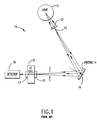
- Fig. 1 shows a prior art type of LC detector system 10.
- a light source 11 provides light to a field lens 12 adjacent to a slit 13 oriented perpendicular to the plane of the drawing.
- a concave grating 14 is disposed to receive light from the slit and focus the same into a pair of flow cells; one such cell 15 is shown in the drawing, the other being above or below the plane of the drawing.
- Orientation of the grating about a vertical axis 16 at the central reflection point determines a wavelength incident on both of the cells.
- End windows 17 retain flowing liquid in the cell bores.
- a photodetector 18 after each cell detects the amount of light transmitted.
- One cell is used as a standard for comparison of the other receiving sample injected into the liquid.
- U.S. patent No. 4,886,356 of the present assignee discloses a detector cell assembly useful for liquid chromatography.
- a problem suggested in the patent is effect of transients due to temperature changes causing non-uniform index of refraction of the liquid in the cell.
- U.S. patent No. 4,011,451 discloses a lens for directing beams of light onto a pair of cells which are diverging so as to keep aberrant light from the walls.
- U.S. patent No. 4,037,974 discloses various methods for blocking light reflected from or through the cell walls.
- U.S. patent No. 3,792,929 discloses a field lens for tunneling radiation through the cell without striking the walls.
- U.K. Patent Application GB 2 116 707 A is directed to minimizing boundary effects in the cell with the use of a field stop and an aperature stop in the optical train directing light into the cell.
- a device disclosed in EP-A-0 168 939 comprises a light stop with an aperture therein adjacent to the light source.
- the aperture is imaged on the entrance window of the cell.
- a light spot smaller than the bore of the cell is generated by the light beam on the entrance window of the cell.
- the imaging path of rays contains a second, aperture light stop at a location where the individual imaging beams are collimated. This second light stop is imaged on the exit window of the cell.
- EP-A-0 422 448 discloses an apparatus for meausring light absorbance in a cylindrical sample cell. Focussing means form a tapered light beam to pass through the sample cell.
- the cell has a lens at one end, on which the light beam is focussed.
- An aperture is located up-beam of the lens. The aperture together with the lens prevents light rays from striking the wall of the cell.
- An object of the invention is to provide a double beam detector system for liquid chromatography, which is relatively low in cost, is low in detector noise and drift, and has reduced sensitivity to spurious effects from sample injections and temperature fluctuations.
- FIG. 1 is a schematic diagram of a prior art double beam detector system for liquid chromatography.
- FIG. 2 is a schematic diagram of a double beam detector system according to the present invention.
- FIG. 3 is an end view of a mask component of FIG. 2.
- FIG. 4 is a sectional view taken at 4-4 of FIG. 2.
- FIG. 5 is a schematic diagram of a system according to a further embodiment of the present invention.
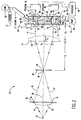
- FIG. 2 shows a simpler aspect of the invention for a double beam detector system 20 for liquid chromatography.
- a small radiation source 22 such as a deuterium lamp provides light radiation 24 to a field lens 26 which focusses the source to a point 28 on the optical axis 30 .
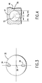
- a slit means 32 adjacent to the field lens consists of an opaque disk with two slits 34 therein spaced diametrically from the axis as shown in FIG. 3. The slits are thus disposed relative to the light source so as to define two beams 36,37 of radiation symmetrical to the optical axis, the beams passing through the common object point 28 coinciding with the focus point.
- a stop 39 with a field aperature 38 may be placed at this point.
- a collimating lens 40 is centered on the axis to be receptive of the beams after the common object point and direct the two beams along respective beam axes 41,42 parallel to each other.
- the two entrance slits 34 may be replaced by a single long slit (not shown), as the central portion of the radiation passing through such a slit will be blocked further along the optical train. Thus only the outer portions of the radiation are of consequence. However the use of two slits is preferred so as to reduce stray radiation.
- the terms "two beams" or “the beams” are used herein and in the claims to mean either separate beams from the separate slits, or the outer portions of the radiation from a single long slit.
- a pair of parallel liquid chromatography (LC) detector cells 43,44 are formed, conveniently in a single body 46 although separate bodies may be used.
- Each cell is generally of the conventional type, for example as described in the aforementioned U.S. patent No. 4,886,356.
- Each cell has a cell bore 47,48 through the body with open ends 50 .
- Each bore has a bore axis 51,52 coinciding with a beam axis 41,42 such that one of the beams passes through each cell bore.
- the detector cells further have transparent entrance windows 53,54 and exit windows 55,56 respectively closing the ends of the bores.
- the windows are the planar inner surfaces of respective plano convex lenses 57,58 as described below.
- a pair of conventional photodetectors 59,60 are each aligned with a cell bore so as to be receptive of a beam passed therethrough and out of the exit windows. Each exit window/lens focuses its beam into a detector. Output signals from the detectors are conveyed on lines 62 to a processing system 64 for comparative analysis and presentation of results.
- Means for flowing liquid through each cell bore include passages 66 leading to each end of the bore (one passage shown for each bore).
- the inlet passages are receptive of liquid from a pump 68 , through tubes 69 , via an LC column 70 for at least one cell.
- the flowing liquid for one cell will have a test sample from an injector 73 for analysis, and the other cell is used for comparison.
- the size of the light source 22 and/or the size of the aperture 38 are sufficiently small so that the beams in the bores 47,48 have a diameter, without regard to aberrations in the optics, substantially smaller than the diameters of the bores. Further means are provided to constrict each beam in the bores to a beam diameter less than the bore diameter. In one aspect this comprises a mask 71 , similar to the mask 32 of FIG.3, with two constricted openings 73 disposed adjacent to respective entrance windows.
- the beam is constricted so as avoid transient effects in the index of refraction or optical absorption near the walls of the cell bores as test samples from an LC column in the liquid reach the cells, or in the event of temperature changes, before equilibrium is reached.
- the beam may be constricted by the openings, preferably the constriction is effected with the optics as explained below.
- the collimating lens 40 and the entrance lenses 57 form a pair of parallel optical trains each having optical parameters selected cooperatively so that the common object point 28 is imaged on each exit window 55,56 .
- the collimating lens consists of a hemispherical lens with a planar surface 74 facing away from the entrance lenses, and the entrance lenses each consists of a hemispherical lens with a planar surface functioning as a respective entrance window 53,54 .
- the selected optical parameters comprise indexes of refraction of all relevant lenses and liquid, radii of curvature and thicknesses T1 and T2 of the collimating lens and the entrance lenses, distance D1 between the common point 28 and the planar surface 74 of the collimating lens, distance D2 between the collimating lens and each entrance window, distance D3 between the entrance window and the exit window (bore length), bore diameters D4 and separation D5 between bore axes.
- the optics and field aperature are to provide for the image 72 (FIG. 4) having a size S less than the bore diameter D4.
- the light source 22 is imaged onto the exit windows by way of an intermediate image at point 28 .
- the theoretical image size (without aberrations) of the light source on the exit windows is the theoretical image size of the field aperture, or the image size of the source itself if sufficiently small.
- the defined image size S is the sum of the theoretical image size on the exit windows 55,56 of the light source (generally as limited by aperature 38 ) and a spot size, the latter being an enlargement of the image due to aberrations.
- the spot size is computed as twice a root-mean-square (rms) spot size, defined conventionally, for example as described in Mathematics of Statistics, Kenney & Keeping, Van Nostrand Co. Inc., Princeton, N.J. (2nd ed. 1959, pages 59-60).
- the spot size is computed from the assumption of a hypothetical point source located at the common object point 28 .
- the finite spot size derives from the aberrations of imperfect optics, for example, the hemispherical shapes of the lenses.
- the spot size may be computed using conventional computer programming, for example with "Beam 3" program sold by Stellar Software, Berkeley, California.
- Such a program generates ray paths through the optical components, for various ray angles initiating at the common object point 28 limited by the entrance aperture 73 and the exit bore diameters D4. Ray angles are taken at equal increments, for example 0.2° increments from zero to 2° from the axis 30 .
- An rms spot size is computed for a set of rays, with selected values for the aforementioned optical parameters. The process is repeated for various values until a minimum image size smaller than bore diameter is ascertained, preferably a minimized spot size.
- the image 72 in FIG. 4 is depicted as a radially decreasing density of points representing rays incident on the window 55 .
- the parameters are predetermined or constrained by other factors, such as the indexes of refraction, distances between components, and bore dimensions and separation.
- Lens thicknesses may also be fixed. Thus iterations are made primarily with radii of the lens surfaces, and changes in other parameters such as distances are made if suitable results are not obtained with the initial selections.
- the ray computations also are used to determine appropriate dimensions for the collimating lens so as to yield the parallel beam axes coinciding with the bore axes.
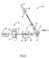
- a detector system 80 further includes a concave reflective dispersion grating 75 as shown in FIG. 5.
- the conventional purpose of the grating is to provide for selections of narrow wavelength bands for liquid chromatographic analyses.
- the choice of the concave grating and its specific placement in the system according to the invention provides for further preferable focusing.
- Other components in the system of FIG. 5 are the same as for FIG. 2, and are numbered accordingly. Further components such as windows are present but not shown for clarity. The foregoing descriptions for all of these components are incorporated by reference for FIG. 5, without repeating here.
- the grating is disposed on the optical axis 30 between the slits 32 and the collimating lens 40 .
- the optical axis is folded at the grating at an angle which provides a selected order of dispersion in the beams at the detector cells. For example with a 1200 lines/mm grating for zero order dispersion the axis is folded at an angle A of 61.6°.
- the grating may be rotatable about another axis 76 through the folding point perpendicular to the plane of the folded optical axis, so as to be oriented to select a wavelength band falling on the detector cells 59,60 .
- the slits (also FIG. 3) are spaced symmetically on a diametric line passing perpendicularly through the optical axis such that the beam axes are also diametrically spaced from the optical axis.
- the grating is oriented so that the dispersion is perpendicular to the diametric line, with the beams comprising a selected wavelength band of radiation in the cell bores.
- the grating has a curvature 78 selected cooperatively with the dimensions of the collimating and entrance lenses and their refractive indexes, and with distances between the entrance slit and the grating, the grating and the collimating lens, and the collimating lens and the entrance windows, so as to focus the entrance slits at respective entrance windows.
- the mask 71 at the entrance windows in this case may additionally or alternatively serve to narrow the width of the wavelength band.
- Other configurations in the system with the grating are as described for FIG. 2, including the focusing of the common object point 28 on the exit window and the parameter selection to minimize rms spot size.
- the double beam detector system of the present invention is compact and relatively low cost with high performance. Transient effects of the refractive index of the liquid, temperature changes, and detector noise and drift are substantially reduced. Accuracy, stability and sensitivity are improved.
Description
- The present invention relates to a double beam detector system for liquid chromatography, comprising
- (a) a source of radiation,
- (b) slit means disposed relative to the source of radiation to effect two beams of radiation symmetrical to an optical axis,
- (c) a pair of parallel detector cells, each including a body having a cell bore therethrough with open ends and further including transparent entrance and exit windows respectively closing the ends of the bores, the entrance windows including entrance lenses, and means for flowing liquid through each cell bore,
- (d) a pair of radiation detectors, each of which is associated with one of the cell bores and arranged to be receptive of a beam passed through the respective cell bore, and
- (e) constriction means for constricting each beam to a beam size in a respective cell bore, the beam size being less than the bore diameter.
- In spectrophotometers for liquid chromatography (LC) a substance whose quantitative presence in a sample is to be determined is injected and dissolved into a suitable liquid carrier solvent, separated in an LC column and flowed through a detector cell which has end windows through which a selected wavelength of ultraviolet or visible light radiation is directed. Radiation exiting from the cell falls on a photodetector having an output recorded by suitable instrumentation which is calibrated to indicate the amount of radiation absorbed by the fluid flowing through the cell. Absorbance is customarily indicated by a graph continuously recorded on a strip chart by a pen recorder. The quantitative presence of a sample substance of interest is determined by measuring the area under the graph peaks which represent the amount of radiation of a particular wavelength that is absorbed, particular materials being identified by particular wavelengths characteristically absorbed by them.
- The sensitivity of a spectrophotometer detector cell is a function particularly of the stability of the base line of the graph. The graph base line is established by the absorbance of the solvent used, and will change in relation to any change in the refractive index of the solvent. The refractive index in turn will be changed by a change in the temperature of the solvent in the cell, or by a transient as a test sample reaches the cell. Transients are particularly associated with temporary changes in refractive index on the fluid near the wall of the cell. When the baseline changes, the true peak area cannot be measured accurately and the peaks themselves become less clearly defined and hence difficult to identify and measure with any reliable degree of accuracy. The sensitivity of the instrument is disproportionally reduced by any change in temperatures or composition of the solvent, thus altering its index of refraction and increasing flow noise.
- Fig. 1 shows a prior art type of
LC detector system 10. Alight source 11 provides light to afield lens 12 adjacent to aslit 13 oriented perpendicular to the plane of the drawing. Aconcave grating 14 is disposed to receive light from the slit and focus the same into a pair of flow cells; onesuch cell 15 is shown in the drawing, the other being above or below the plane of the drawing. Orientation of the grating about avertical axis 16 at the central reflection point determines a wavelength incident on both of the cells. Endwindows 17 retain flowing liquid in the cell bores. Aphotodetector 18 after each cell detects the amount of light transmitted. One cell is used as a standard for comparison of the other receiving sample injected into the liquid. - U.S. patent No. 4,886,356 of the present assignee discloses a detector cell assembly useful for liquid chromatography. A problem suggested in the patent is effect of transients due to temperature changes causing non-uniform index of refraction of the liquid in the cell. Thermal insulation offered by the patent disclosure, or in other cases a heat sink, alleviate the temperature effects; however similar effects may result when test sample injected into the liquid reaches the cell, before equilibrium is reached. Small size of such cells is directed to minimizing such effects but has become insufficient for improved sensitivity and accurary.
- U.S. patent No. 4,011,451 discloses a lens for directing beams of light onto a pair of cells which are diverging so as to keep aberrant light from the walls. U.S. patent No. 4,037,974 discloses various methods for blocking light reflected from or through the cell walls. U.S. patent No. 3,792,929 discloses a field lens for tunneling radiation through the cell without striking the walls. U.K.
Patent Application GB 2 116 707 A is directed to minimizing boundary effects in the cell with the use of a field stop and an aperature stop in the optical train directing light into the cell. - In order to ensure that no light rays of the beam will hit the walls of the bore of the cell, while ensuring, on the other hand, maximum utilization of the cell volume, a device disclosed in EP-A-0 168 939 comprises a light stop with an aperture therein adjacent to the light source. The aperture is imaged on the entrance window of the cell. Thus a light spot smaller than the bore of the cell is generated by the light beam on the entrance window of the cell. In order to safely prevent rays incident at an angle from hitting the wall of the bore, the imaging path of rays contains a second, aperture light stop at a location where the individual imaging beams are collimated. This second light stop is imaged on the exit window of the cell.
- EP-A-0 422 448 discloses an apparatus for meausring light absorbance in a cylindrical sample cell. Focussing means form a tapered light beam to pass through the sample cell. The cell has a lens at one end, on which the light beam is focussed. An aperture is located up-beam of the lens. The aperture together with the lens prevents light rays from striking the wall of the cell.
- An object of the invention is to provide a double beam detector system for liquid chromatography, which is relatively low in cost, is low in detector noise and drift, and has reduced sensitivity to spurious effects from sample injections and temperature fluctuations.
- According to the invention, this object is achieved in that
- (f) collimating means are disposed to direct the two beams along respective beam axes parallel to the optical axis,
- (g) each cell bore has a bore diameter and a bore axis coinciding with a beam axis such that one of the beams passes through each cell bore,
- (h) each of the detectors is aligned with an associated cell bore,
- (i) the constriction means comprise:
- a field lens disposed adjacently to the slit means so as to focus the two beams through a common point on the optical axis between the slit means and the entrance lenses, the collimating means being a lens centered on the optical axis between the common point and the entrance lenses,
- the collimating lens and each of the entrance lenses being selected cooperatively so that the common point is imaged on each of the exit windows with a spot size, the spot size being such that the sum of the image size of the source of radiation on the ewit windows and the spot size is less than each bore diameter.
- FIG. 1 is a schematic diagram of a prior art double beam detector system for liquid chromatography.
- FIG. 2 is a schematic diagram of a double beam detector system according to the present invention.
- FIG. 3 is an end view of a mask component of FIG. 2.
- FIG. 4 is a sectional view taken at 4-4 of FIG. 2.
- FIG. 5 is a schematic diagram of a system according to a further embodiment of the present invention.
- FIG. 2 shows a simpler aspect of the invention for a double
beam detector system 20 for liquid chromatography. Asmall radiation source 22 such as a deuterium lamp provideslight radiation 24 to afield lens 26 which focusses the source to apoint 28 on theoptical axis 30. A slit means 32 adjacent to the field lens consists of an opaque disk with twoslits 34 therein spaced diametrically from the axis as shown in FIG. 3. The slits are thus disposed relative to the light source so as to define twobeams common object point 28 coinciding with the focus point. Astop 39 with afield aperature 38 may be placed at this point. Acollimating lens 40 is centered on the axis to be receptive of the beams after the common object point and direct the two beams alongrespective beam axes - The two
entrance slits 34 may be replaced by a single long slit (not shown), as the central portion of the radiation passing through such a slit will be blocked further along the optical train. Thus only the outer portions of the radiation are of consequence. However the use of two slits is preferred so as to reduce stray radiation. The terms "two beams" or "the beams" are used herein and in the claims to mean either separate beams from the separate slits, or the outer portions of the radiation from a single long slit. - A pair of parallel liquid chromatography (LC)
detector cells single body 46 although separate bodies may be used. Each cell is generally of the conventional type, for example as described in the aforementioned U.S. patent No. 4,886,356. Each cell has a cell bore 47,48 through the body with open ends 50. Each bore has abore axis beam axis transparent entrance windows exit windows convex lenses conventional photodetectors lines 62 to aprocessing system 64 for comparative analysis and presentation of results. - Means for flowing liquid through each cell bore include
passages 66 leading to each end of the bore (one passage shown for each bore). The inlet passages are receptive of liquid from apump 68, throughtubes 69, via anLC column 70 for at least one cell. Typically the flowing liquid for one cell will have a test sample from aninjector 73 for analysis, and the other cell is used for comparison. - The size of the
light source 22 and/or the size of theaperture 38 are sufficiently small so that the beams in thebores mask 71, similar to themask 32 of FIG.3, with two constrictedopenings 73 disposed adjacent to respective entrance windows. - The beam is constricted so as avoid transient effects in the index of refraction or optical absorption near the walls of the cell bores as test samples from an LC column in the liquid reach the cells, or in the event of temperature changes, before equilibrium is reached. Although the beam may be constricted by the openings, preferably the constriction is effected with the optics as explained below.
- The collimating
lens 40 and theentrance lenses 57 form a pair of parallel optical trains each having optical parameters selected cooperatively so that thecommon object point 28 is imaged on eachexit window planar surface 74 facing away from the entrance lenses, and the entrance lenses each consists of a hemispherical lens with a planar surface functioning as arespective entrance window common point 28 and theplanar surface 74 of the collimating lens, distance D₂ between the collimating lens and each entrance window, distance D₃ between the entrance window and the exit window (bore length), bore diameters D₄ and separation D₅ between bore axes. - To constrict the beam in the bore, the optics and field aperature are to provide for the image 72 (FIG. 4) having a size S less than the bore diameter D4. The
light source 22 is imaged onto the exit windows by way of an intermediate image atpoint 28. The theoretical image size (without aberrations) of the light source on the exit windows is the theoretical image size of the field aperture, or the image size of the source itself if sufficiently small. The defined image size S is the sum of the theoretical image size on theexit windows common object point 28. The finite spot size derives from the aberrations of imperfect optics, for example, the hemispherical shapes of the lenses. The spot size may be computed using conventional computer programming, for example with "Beam 3" program sold by Stellar Software, Berkeley, California. - Such a program generates ray paths through the optical components, for various ray angles initiating at the
common object point 28 limited by theentrance aperture 73 and the exit bore diameters D₄. Ray angles are taken at equal increments, for example 0.2° increments from zero to 2° from theaxis 30. An rms spot size is computed for a set of rays, with selected values for the aforementioned optical parameters. The process is repeated for various values until a minimum image size smaller than bore diameter is ascertained, preferably a minimized spot size. Theimage 72 in FIG. 4 is depicted as a radially decreasing density of points representing rays incident on thewindow 55. Generally certain of the parameters are predetermined or constrained by other factors, such as the indexes of refraction, distances between components, and bore dimensions and separation. Lens thicknesses may also be fixed. Thus iterations are made primarily with radii of the lens surfaces, and changes in other parameters such as distances are made if suitable results are not obtained with the initial selections. The ray computations also are used to determine appropriate dimensions for the collimating lens so as to yield the parallel beam axes coinciding with the bore axes. - In a preferred aspect of the invention, a
detector system 80 further includes a concave reflective dispersion grating 75 as shown in FIG. 5. The conventional purpose of the grating is to provide for selections of narrow wavelength bands for liquid chromatographic analyses. However the choice of the concave grating and its specific placement in the system according to the invention provides for further preferable focusing. Other components in the system of FIG. 5 are the same as for FIG. 2, and are numbered accordingly. Further components such as windows are present but not shown for clarity. The foregoing descriptions for all of these components are incorporated by reference for FIG. 5, without repeating here. - The grating is disposed on the
optical axis 30 between theslits 32 and thecollimating lens 40. The optical axis is folded at the grating at an angle which provides a selected order of dispersion in the beams at the detector cells. For example with a 1200 lines/mm grating for zero order dispersion the axis is folded at an angle A of 61.6°. The grating may be rotatable about anotheraxis 76 through the folding point perpendicular to the plane of the folded optical axis, so as to be oriented to select a wavelength band falling on thedetector cells - The slits (also FIG. 3) are spaced symmetically on a diametric line passing perpendicularly through the optical axis such that the beam axes are also diametrically spaced from the optical axis. The grating is oriented so that the dispersion is perpendicular to the diametric line, with the beams comprising a selected wavelength band of radiation in the cell bores. The grating has a
curvature 78 selected cooperatively with the dimensions of the collimating and entrance lenses and their refractive indexes, and with distances between the entrance slit and the grating, the grating and the collimating lens, and the collimating lens and the entrance windows, so as to focus the entrance slits at respective entrance windows. - The
mask 71 at the entrance windows in this case may additionally or alternatively serve to narrow the width of the wavelength band. Other configurations in the system with the grating are as described for FIG. 2, including the focusing of thecommon object point 28 on the exit window and the parameter selection to minimize rms spot size. - Selected parameters and computed dimensions are set forth in Table 1 to provide a specific example for a detector system according to the present invention.

- The double beam detector system of the present invention, particularly with the grating, is compact and relatively low cost with high performance. Transient effects of the refractive index of the liquid, temperature changes, and detector noise and drift are substantially reduced. Accuracy, stability and sensitivity are improved.
- While the invention has been described above in detail with reference to specific embodiments, various changes and modifications which fall within the scope of the appended claims will become apparent to those skilled in this art. Therefore, the invention is intended only to be limited by the appended claims or their equivalents.
Claims (7)
- A double beam detector system for liquid chromatography, comprising(a) a source (22) of radiation,(b) slit means (32) disposed relative to the source (22) of radiation to effect two beams (36,37) of radiation symmetrical to an optical axis (30),(c) a pair of parallel detector cells (43,44), each including a body (46) having a cell bore (47,48) therethrough with open ends and further including transparent entrance and exit windows (53,54;55,56) respectively closing the ends of the bores (47,48), the entrance windows including entrance lenses (57), and means for flowing liquid through each cell bore,(d) a pair of radiation detectors ((59,60), each of which is associated with one of the cell bores (47,48) and arranged to be receptive of a beam passed through the respective cell bore (47,48), and(e) constriction means for constricting each beam (36,37) to a beam size in a respective cell bore (47,48), the beam size being less than the bore diameter,characterized in that(f) collimating means (40) are disposed to direct the two beams (36,37) along respective beam axes parallel to the optical axis,(g) each cell bore (47,48) has a bore diameter and a bore axis coinciding with a beam axis such that one of the beams (36,37) passes through each cell bore,(h) each of the detectors (59,60) is aligned with an associated cell bore (47,48),(i) the constriction means comprise:- a field lens (26) disposed adjacently to the slit means (32) so as to focus the two beams (36,37) through a common point (28) on the optical axis between the slit means (32) and the entrance lenses (57), the collimating means being a lens (40) centered on the optical axis between the common point (28) and the entrance lenses (57),- the collimating lens (40) and each of the entrance lenses (57) being selected with their optical parameters cooperatively so that the common point (28) is imaged on each of the exit windows (55,56) with a spot size, the spot size being such that the sum of the image size of the source of radiation on the exit windows and the spot size is less than each bore diameter.
- A double beam detector system as claimed in claim 1, characterized by masking means (71) with two openings (73) therein each disposed adjacently to a respective entrance window (53,54).
- A double beam detector system as claimed in claim 1, characterized in that each of the entrance lenses (57) consists of a planoconvex lens with a planar surface functioning as a respective entrance window (53,54).
- A double beam detector system as claimed in anyone of the claims 1 to 3, characterized in that the collimating lens (40) consists of a hemispherical lens with a planar surface facing away from the entrance lenses (57), each of the entrance lenses (57) consists of a hemispherical lens with a planar surface functioning as a respective entrance window (53,54), and the optical parameters comprise radii of curvature and thickneses of the collimating lens (40) and the entrance lenses (57), distance between the common point (28) and the collimating lens (40), distance between the collimating lens (40) and each entrance lens (57), distance between the entrance lens (57) and and the exit window (55,56), bore diameter and separation between bore axes.
- A double beam detector system as claimed in anyone of the claims 1 to 4, characterized in that the spot size is twice a root-mean-square spot size.
- A double beam detector system as claimed in anyone of the claims 1 to 5, characterized in that a concave reflective dispersion grating (75) is positioned on the optical axis between the slit means (32) and the collimating lens (40), the optical axis being folded at the grating at an angle selected to provide a selected order of dispersion in the beams at the detector cells (47), the slit means (32) being symmetrical to a diametric line passing perpendicularly through the optical axis, the grating (75) being oriented so that the dispersion is perpendicular to the diametric line with the beams comprising a selected wavelength band of radiation in the cell bores (47,48), and the grating (75) having a curvature (78) selected cooperatively with the collimating lens (40), entrance lens (57) and distances between the entrance slit and the grating (75), the grating (75) and the collimating lens (40), and the collimating lens (40) and the entrance windows (53,54) so as to focus the entrance slits at respective entrance windows (53,54).
- A double beam detector system as claimed in claim 6, characterized in that masking means (71) with two constricted openings (73) therein are provided, each opening (73) being disposed adjacently to a respective entrance window (53,54) to effect the beams in the cell bores (47,48) as a narrow wavelength band of radiation.
Applications Claiming Priority (2)
| Application Number | Priority Date | Filing Date | Title |
|---|---|---|---|
| US07/751,415 US5173742A (en) | 1991-08-28 | 1991-08-28 | Double beam detector system for liquid chromatography |
| US751415 | 1991-08-28 |
Publications (2)
| Publication Number | Publication Date |
|---|---|
| EP0529541A1 EP0529541A1 (en) | 1993-03-03 |
| EP0529541B1 true EP0529541B1 (en) | 1996-04-17 |
Family
ID=25021882
Family Applications (1)
| Application Number | Title | Priority Date | Filing Date |
|---|---|---|---|
| EP92114331A Expired - Lifetime EP0529541B1 (en) | 1991-08-28 | 1992-08-21 | Double beam detector system for liquid chromatography |
Country Status (3)
| Country | Link |
|---|---|
| US (1) | US5173742A (en) |
| EP (1) | EP0529541B1 (en) |
| DE (1) | DE69209936T2 (en) |
Families Citing this family (7)
| Publication number | Priority date | Publication date | Assignee | Title |
|---|---|---|---|---|
| FR2708111B1 (en) * | 1993-07-19 | 1995-09-01 | Inst Francais Du Petrole | System intended to create the same instantaneous pressure between two tanks. |
| US5438420A (en) * | 1993-08-09 | 1995-08-01 | Vickers, Incorporated | Monitoring of fluid contamination level wherein the light energy is focused on the fluid passage means |
| US5815276A (en) * | 1996-10-11 | 1998-09-29 | Transgenomic Inc. | Long-path absorbance-cell imaging system with decreased system element parameter change based sensitivity and method of use |
| AU2004215325B2 (en) * | 2003-02-27 | 2009-01-08 | Agilent Technologies Australia (M) Pty Ltd | Spectrophotometer |
| AU2003900902A0 (en) * | 2003-02-27 | 2003-03-13 | Varian Australia Pty Ltd | Spectrophotometer |
| US7075652B1 (en) * | 2004-11-12 | 2006-07-11 | Ibet, Inc. | Apparatus and method for measuring temperature dependent properties of liquid |
| JP6062837B2 (en) * | 2013-09-30 | 2017-01-18 | 株式会社日立ハイテクノロジーズ | Detector for liquid chromatography |
Family Cites Families (16)
| Publication number | Priority date | Publication date | Assignee | Title |
|---|---|---|---|---|
| DE1598274A1 (en) * | 1965-07-06 | 1971-02-18 | Ceskoslovenska Akademie Ved | Cuvette unit |
| GB1155438A (en) * | 1966-09-14 | 1969-06-18 | Ceskoslovenska Akademie Ved | Photometer with Limited Light-Beam in Flow-Through Measuring Cell |
| US3591801A (en) * | 1968-03-21 | 1971-07-06 | Picker Corp | Double beam optical absorption photometer having sample and reference chambers positioned along a single optical axis |
| US3792929A (en) * | 1972-05-24 | 1974-02-19 | Electro Nucleonics | Spectrophotometer utilizing fluid lens means |
| US3795450A (en) * | 1973-01-18 | 1974-03-05 | Varian Associates | Dual beam optical absorption photometry detector assembly for high pressure applications |
| US4037974A (en) * | 1974-10-17 | 1977-07-26 | Fletcher Taylor C | Sample cell for spectrophotometers |
| US4011451A (en) * | 1975-07-03 | 1977-03-08 | Waters Associates, Incorporated | Novel photometric system |
| JPS52100277A (en) * | 1976-02-19 | 1977-08-23 | Hitachi Ltd | Absorption photometer |
| GB2116707A (en) * | 1982-03-01 | 1983-09-28 | Varian Associates | Optical system for a liquid flow absorption cell |
| JPS60128328A (en) * | 1983-12-16 | 1985-07-09 | Hitachi Ltd | Flow cell of photometer |
| JPS61105445A (en) * | 1984-05-28 | 1986-05-23 | Shimadzu Corp | Flow cell for measuring light absorbancy |
| EP0168939A3 (en) * | 1984-06-13 | 1987-08-05 | Varian Associates, Inc. | Liquid chromatographic eluent absorbance detector |
| JPS61225636A (en) * | 1985-03-29 | 1986-10-07 | Shimadzu Corp | Flow-through optical cell |
| US4838688A (en) * | 1987-10-16 | 1989-06-13 | Robert Rhoads | High sensitivity chromatography detector |
| US4886356A (en) * | 1988-04-01 | 1989-12-12 | The Perkin-Elmer Corporation | Detector cell for liquid chromatography |
| EP0422448B1 (en) * | 1989-09-29 | 1995-11-29 | Waters Investments Limited | Apparatus for measuring light absorbance or fluorescence in liquid samples |
-
1991
- 1991-08-28 US US07/751,415 patent/US5173742A/en not_active Expired - Lifetime
-
1992
- 1992-08-21 DE DE69209936T patent/DE69209936T2/en not_active Expired - Fee Related
- 1992-08-21 EP EP92114331A patent/EP0529541B1/en not_active Expired - Lifetime
Also Published As
| Publication number | Publication date |
|---|---|
| DE69209936D1 (en) | 1996-05-23 |
| DE69209936T2 (en) | 1996-12-12 |
| EP0529541A1 (en) | 1993-03-03 |
| US5173742A (en) | 1992-12-22 |
Similar Documents
| Publication | Publication Date | Title |
|---|---|---|
| EP0626064B1 (en) | Methods and apparatus for molecular characterization | |
| EP0717839B1 (en) | A high efficiency fluorescence flow cell | |
| US5153679A (en) | Apparatus and process for measuring light absorbance or fluorescence in liquid samples | |
| US5235409A (en) | Optical detection system for capillary separation columns | |
| US4747687A (en) | Ball cell windows for spectrophotometers | |
| EP1141675B1 (en) | Dual pathlength system for light absorbance detection | |
| US4475813A (en) | Divergent light optical systems for liquid chromatography | |
| US4795262A (en) | Liquid chromatography absorbance detector | |
| US5428696A (en) | Photometric instrument with optical fibers for analyzing remote samples | |
| US5274227A (en) | Capillary detector cell having imaging elements positioned to optimize sensitivity | |
| US4276475A (en) | Novel photometric system | |
| US5428222A (en) | Spectral analyzer with new high efficiency collection optics and method of using same | |
| Bruno et al. | On-column capillary flow cell utilizing optical waveguides for chromatographic applications | |
| EP0615617A1 (en) | Capillary flowcell for multiple wavelength detection | |
| EP0422448B1 (en) | Apparatus for measuring light absorbance or fluorescence in liquid samples | |
| EP0529541B1 (en) | Double beam detector system for liquid chromatography | |
| EP1159588A1 (en) | Compact and robust spectrograph | |
| US3606547A (en) | Spectrophotometer | |
| US5815276A (en) | Long-path absorbance-cell imaging system with decreased system element parameter change based sensitivity and method of use | |
| JPS61290342A (en) | Detector for absorbancy of eluent for liquid chromatography | |
| USRE36489E (en) | Spectral analyzer with new high efficiency collection optics and method of using same | |
| US4468124A (en) | Double beam photometer for measuring fluid samples | |
| EP0168939A2 (en) | Liquid chromatographic eluent absorbance detector | |
| Kaltenbach | A high-sensitivity diode array detector for on-column detection in capillary electrophoresis | |
| JPH02227637A (en) | Fluorophotometer |
Legal Events
| Date | Code | Title | Description |
|---|---|---|---|
| PUAI | Public reference made under article 153(3) epc to a published international application that has entered the european phase |
Free format text: ORIGINAL CODE: 0009012 |
|
| AK | Designated contracting states |
Kind code of ref document: A1 Designated state(s): CH DE GB IT LI NL |
|
| 17P | Request for examination filed |
Effective date: 19930312 |
|
| 17Q | First examination report despatched |
Effective date: 19950511 |
|
| GRAH | Despatch of communication of intention to grant a patent |
Free format text: ORIGINAL CODE: EPIDOS IGRA |
|
| GRAA | (expected) grant |
Free format text: ORIGINAL CODE: 0009210 |
|
| AK | Designated contracting states |
Kind code of ref document: B1 Designated state(s): CH DE GB IT LI NL |
|
| REF | Corresponds to: |
Ref document number: 69209936 Country of ref document: DE Date of ref document: 19960523 |
|
| ITF | It: translation for a ep patent filed |
Owner name: STUDIO JAUMANN |
|
| PLBE | No opposition filed within time limit |
Free format text: ORIGINAL CODE: 0009261 |
|
| STAA | Information on the status of an ep patent application or granted ep patent |
Free format text: STATUS: NO OPPOSITION FILED WITHIN TIME LIMIT |
|
| 26N | No opposition filed | ||
| REG | Reference to a national code |
Ref country code: GB Ref legal event code: 732E |
|
| PGFP | Annual fee paid to national office [announced via postgrant information from national office to epo] |
Ref country code: CH Payment date: 20000803 Year of fee payment: 9 |
|
| PGFP | Annual fee paid to national office [announced via postgrant information from national office to epo] |
Ref country code: NL Payment date: 20000808 Year of fee payment: 9 |
|
| PG25 | Lapsed in a contracting state [announced via postgrant information from national office to epo] |
Ref country code: CH Free format text: LAPSE BECAUSE OF NON-PAYMENT OF DUE FEES Effective date: 20010831 Ref country code: LI Free format text: LAPSE BECAUSE OF NON-PAYMENT OF DUE FEES Effective date: 20010831 |
|
| REG | Reference to a national code |
Ref country code: GB Ref legal event code: IF02 |
|
| PG25 | Lapsed in a contracting state [announced via postgrant information from national office to epo] |
Ref country code: NL Free format text: LAPSE BECAUSE OF NON-PAYMENT OF DUE FEES Effective date: 20020301 |
|
| REG | Reference to a national code |
Ref country code: CH Ref legal event code: PL |
|
| NLV4 | Nl: lapsed or anulled due to non-payment of the annual fee |
Effective date: 20020301 |
|
| PGFP | Annual fee paid to national office [announced via postgrant information from national office to epo] |
Ref country code: GB Payment date: 20080827 Year of fee payment: 17 |
|
| PGFP | Annual fee paid to national office [announced via postgrant information from national office to epo] |
Ref country code: DE Payment date: 20080930 Year of fee payment: 17 |
|
| PGFP | Annual fee paid to national office [announced via postgrant information from national office to epo] |
Ref country code: IT Payment date: 20081017 Year of fee payment: 17 |
|
| GBPC | Gb: european patent ceased through non-payment of renewal fee |
Effective date: 20090821 |
|
| PG25 | Lapsed in a contracting state [announced via postgrant information from national office to epo] |
Ref country code: DE Free format text: LAPSE BECAUSE OF NON-PAYMENT OF DUE FEES Effective date: 20100302 |
|
| PG25 | Lapsed in a contracting state [announced via postgrant information from national office to epo] |
Ref country code: GB Free format text: LAPSE BECAUSE OF NON-PAYMENT OF DUE FEES Effective date: 20090821 |
|
| PG25 | Lapsed in a contracting state [announced via postgrant information from national office to epo] |
Ref country code: IT Free format text: LAPSE BECAUSE OF NON-PAYMENT OF DUE FEES Effective date: 20090821 |